1
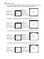
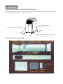
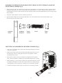
PORTABLE TYPE AIR CONDITIONER
PORTABLE REFRIGERATED AIR CONDITIONER
USER MANUAL
USER
MANUAL
POLOCOOL
For
POLOCOOL
For
PC-58AP/C
PC-53AP/C
PC-44BP/C
PC-35AP/C
20,000 BTU(6.0kW)
NC
19,000 BTU(5.5kW)
NC
15,000 BTU(4.4kW)
12,000 BTU(3.5kW)
34/BP
39/BP
Thank you for selecting our quality air conditioner. Please be sure to read this user manual carefully before using.
POLOCOOL Portable Refrigerated Air Conditioners are imported and distributed throughout Australasia by POLO.
Any enquiries should be directed to POLO on1800 087 840 in the first instance
Thank
you558for
ABN
80 749 103
selecting our quality air conditioner. please be sure to read this user manual
17 Brett Drive,
Carrum before
Downs, using.
VIC 3201
carefully
Any question, please contact the professional service for help.
www.polocool.com.au
Important Issues Regarding the Proper Use of
this Air Conditioner
Please contact Polo on 1800 087 840 for advice
before returning unit to the place of purchase
Use this air conditioner only as described in this instruction manual.
• T
his appliance is fitted with a special safety device. When the compressor switches off or when the appliance
is first turned on, this device prevents the compressor from switching on again for at least three minutes.
• This air conditioner has been designed and manufactured to operate in a domestic situation only and should
not be used for other purposes.
• The appliance is not intended for use by young children or infirm persons.
• Never use the air conditioner in damp rooms (eg bathrooms and laundries)
• If the power cord is damaged, it must be replaced with a new cord installed by a suitably qualified person or
POLO serviceman.
• This air conditioner is designed to be connected to a standard 10 amp power supply outlet.
• Do not pull on or place strain on the power cord when using the appliance.
• Do not operate or stop the appliance by inserting or pulling out the power plug. Use the on/off switch on the
air conditioner control panel or the remote control.
• Due to potential safety hazards, do not use an extension cord or share the power supply outlet with other
appliances. Do not connect to multiple power outlets on extension leads.
• Do not rest hot or heavy objects on the appliance.
• Always unplug the unit from the power outlet before cleaning or maintenance operations, for example
filter cleaning.
• Do not place the air conditioner or plastic window slider in direct sunlight.
• For maximum cooling efficiency keep the exhaust hose as short and as free of bends as possible.
• Clean the filters at least once every two weeks.
• Do not splash the unit with water.
• Do not move the unit by pulling the exhaust hose attached to the back of the unit.
• Do not move air conditioner when it is operating.
• Do not use the unit with the air intake and outlet grills closed, covered or obstructed.
• Before transporting the air conditioner, drain the water pan in accordance with the instructions on page 15.
After transportation, wait at least one hour before switching the unit on.
• The unit should be transported in a vertical position. If this is not possible, secure the unit at an angle, do not
lay it horizontally.
• Do not operate the air conditioner outdoors or in areas open to the outdoors.
• If the air conditioner is only being used as a spot cooler (simply to put cool air directly on a person or thing),
do not connect the rear exhaust outlet.
• If the compressor runs without cool air coming out of the top air outlet after 10 minutes of correct operation,
switch off the unit and contact POLO immediately.
• When the compressor is running, hot air should always be expelled from the bottom rear outlet. If it is not,
switch off and contact POLO immediately.
• At high temperatures to protect the unit from overheating the compressor may stop. Air will flow out of the
front air outlet but it will not be cooled. In this event, switch off the appliance for approximately one hour to
enable the thermal cut out to self reset. The unit may then be operated in the normal manner.
THIS PRODUCT IS FOR HOUSEHOLD USE ONLY
RETAIN THIS MANUAL FOR FUTURE REFERENCE
1
CONTENTS
Introduction......................................................................................... 3
Installation........................................................................................... 7
Control panel....................................................................................... 11
Operation of control panel.................................................................. 11
Operation of remote control................................................................ 13
Water drainage methods...................................................................... 15
Maintenance and service..................................................................... 16
Trouble shooting................................................................................. 18
2
INTRODUCTION
This portable air conditioner can alter the room temperature and humidity. It has multiple functions of cooling dehumidifying
(drying) and fan ventilation, and can be moved from room to room and transported from building to building easily.
The air conditioner can maintain set room indoor air temperatures between 18°C and 32°C. The set room temperature is
displayed on the remote control and in the control panel on the unit. This does not mean that the air conditioner will necessarily
reduce the actual room temperature to the set room temperature.
1 HOW YOUR POLOCOOL PORTABLE
REFRIGERATED AIR CONDITIONER WORKS
Air from the room is drawn into the air conditioner, cooled by
refrigeration, and blown into the room through the front grill.
hot air
(outside)
cool air
Hot air is blown outside through the exhaust hose, using the
window kit supplied with the air conditioner.
room air
Hot air must be exhausted outside the room being cooled,
or you will not cool the room.
2 VARIABLES INFLUENCING THE COOLING
EFFECTIVENESS OF THIS AIR CONDITIONER
N
W
E
S
The ability of the air conditioner to cool the air in your room depends
on a number of variables. The critical variables are:
1. Orientation of the room to the sun.
Rooms facing North and West are exposed to the midday and afternoon
sun, and are the hottest in the house. Rooms facing the morning sun
(East), and away from the sun (South), are the coolest in the house.
morning
afternoon
2. Insulation
sun
sun
Insulated roofs and walls reduce the amount of heat entering the room.
Windows admit heat into the room. This heat can be reduced if the windows are
protected from the direct sun (eg by outside blinds, well lined inside curtains, pergolas, thick foliage etc).
3. Air Draughts
Rooms protected from draughts are more easily cooled. Windows and doors must be kept closed.
4. Multi Storey Buildings
In multi storey buildings, upper storey rooms are usually hotter and therefore harder to cool than
ground floor rooms.
3 SIZING GUIDE
In general the higher the cooling capacity (BTU/kW) of an air conditioner, the bigger the room it will cool.
(a) The PC-53AP/C – 19,000 BTU air conditioner, subject to the variables explained in box 2, can effectively
cool rooms with a floor area of between 18 and 39 square metres.
6.5m
Example 1:
Uninsulated upper storey
room with one West facing
external wall.
In this example, the air
conditioner is suitable for
effectively cooling a room
of up to 18 square metres.
4.5m
4m
Example of maximum
room size
4m x 4.5m = 18m2
Example 2:
Insulated ground floor
room with external
walls facing East
and/or South.
6m
In this example, the air
conditioner is suitable for
effectively cooling a room
of up to 39 square metres.
Example of maximum
room size
6m x 6.5m = 39m2
(b) The PC-44BP/C – 15,000 BTU air conditioner, subject to the variables explained in box 2, can effectively
cool rooms with a floor area of between 9 and 30 square metres.
3
Example 1:
3m
Example 2:
Insulated ground floor
6m
In multi storey buildings, upper storey rooms are usually hotter and therefore harder to cool than
ground floor rooms.
3 SIZING GUIDE
In general the higher the cooling capacity (BTU/kW) of an air conditioner, the bigger the room it will cool.
(a) TThe
PC-53AP/C –– 20,000
19,000 BTU
BTU air
air conditioner,
conditioner, subject
subject to
to the
the variables
variables as
explained
in box
2, can
(a)
he PC-58AP/C
explained
in point
2, effectively
cooleffectively
rooms with
a floor
area
of between
18 of
and
39 square
metres.
can
cool
rooms
with
a floor area
between
20 and
42 square metres.
6.5m
7m
Example 1:
Example 1:
Uninsulated upper storey
Uninsulated upper storey
room with one West facing
room with one West facing
external wall.
external wall.
4m
4m
In this example, the air
In this example, the air
conditioner is suitable for
conditioner is suitable for
effectively cooling a room
effectively cooling a room
of up to 18 square metres.
of up to 20 square metres.
4.5m
5m
Example of maximum
Example
of minimum
room
size
room size
4m x 4.5m = 18m22
4m x 5m = 20m
Example 2:
Example 2:
Insulated ground floor
Insulated ground floor
room with external
room with external
walls facing East
walls facing East
6m
and/or South.
6m
and/or South.
In this example, the air
In this example, the air
conditioner is suitable for
conditioner is suitable for
effectively cooling a room
effectively cooling a room
of up to 39 square metres.
of up to 42 square metres.
Example of maximum
Example of maximum
room size
room size
6m x 6.5m = 39m22
6m x 7m = 42m
(b) The PC-44BP/C – 15,000 BTU air conditioner, subject to the variables explained in box 2, can effectively
cool rooms with a floor area of between 9 and 30 square metres.
6m
(b)The PC53AP/C – 19,000 BTU air conditioner, subject to the variables as explained in point 2, can
effectively cool rooms with a floor area of between 18 and 39 square metres
Example 1:
Uninsulated upper storey
room with one West facing
Example 1:
external wall.
Uninsulated upper storey 3m
In
thiswith
example,
the air
room
one West
facing
conditioner
external
wall.is suitable for
effectively cooling a room 4m
In
example,
air
of this
up to
9 squarethe
metres.
conditioner is suitable for
effectively cooling a room
of up to 18 square metres.
3m
4.5m
Example of maximum
room size
3m x 3m = 9m2
Example of minimum
room size
4.5m x 4m = 18m
2
6.5m
Example 2:
Insulated ground floor
room with external
Example
2: East
walls facing
Insulated
ground floor 5m
and/or South.
room with external
In thisfacing
example,
walls
East the air
conditioner
is
6m
and/or South. suitable for
effectively cooling a room
In
example,
themetres.
air
of this
up to
30 square
conditioner is suitable for
effectively cooling a room
of up to 39 square metres.
Example of maximum
room size
6m x 5m = 30m2
Example of maximum
room size
6.5m x 6m = 39m2
4 TIPS ON GETTING THE MOST OUT OF YOUR
POLOCOOL
PORTABLE AIR CONDITIONER
(c)The PC-44BP/C – 15,000 BTU air conditioner, subject to the variables as explained in point 2,
can effectively
cool rooms with
floordesigned
area of between
9 and
30 square
Portable
air conditioners
areanot
to cool
large
openmetres.
spaces.
To maximise the cooling effectiveness in an enclosed room:
6m
Example
2: before the room heats up. It is more
on early in
the day
• Turn the air conditioner 3m
Example 1:
Insulated ground floor
efficient
the air conditioner to maintain
the room at a comfortable temperature
Uninsulated
upperfor
storey
room with external
Example of maximum
room with
one
facing
than
itWest
is to
reduce an already hot walls
room
to East
a comfortable level.
facing
room size
5m
external wall.
Example of minimum
and/or South.
3m
• Close
windows, curtainsInand
external
blinds
In this
example,all
thedoors,
air
this example,
the air
3m x 3m = 9m2
conditioner is suitable for
conditioner is suitable for
effectively cooling a room
effectively cooling a room
• Seal or block major draughts.
of up to 9 square metres.
of up to 30 square metres.
room size
x 5m = 30m
of the6mroom
being cooled.
2
(d)The PC-35AP/C – 12,000 BTU air conditioner, subject to the variables as explained in point 2,
can effectively cool rooms with a floor area of between 6 and 20 square metres.
5m
Example 1:
Uninsulated upper storey
room with one West facing
external wall.
In this example, the air
conditioner is suitable for
effectively cooling a room
of up to 6 square metres.
3m
2m
Example of minimum
room size
3m x 2m = 6m2
Example 2:
Insulated ground floor
room with external
walls facing East
and/or South.
4m
In this example, the air
conditioner is suitable for
effectively cooling a room
of up to 20 square metres.
4
Example of maximum
room size
4m x 5m = 20m2
effectively cooling a room
of up to 9 square metres.
effectively cooling a room
of up to 30 square metres.
4 TIPS ON GETTING THE MOST OUT OF YOUR
INTRODUCTION
POLOCOOL
PORTABLE AIR CONDITIONER
This portable air conditioner can alter the room temperature and humidity. It has multiple functions of cooling,
Portable
air
conditioners
are
not
designed
toand
cool
large from
open
spaces.
Portable
conditioners
not
designed
to
cool
large
open
spaces.
dehumidifying (drying)
and fanair
ventilation,
and can beare
moved
from
room to room
transported
building
to
To
maximise
the
cooling
effectiveness
in
an
enclosed
room:
building easily.
To maximise the cooling effectiveness in an enclosed room:
•Turn the air conditioner on early in the day before the room heats up. It is more
before
theatroom
heats up. Ittemperature
is more
the
room
a comfortable
efficient
for
the
air
conditioner
to
maintain
the
room
at
a
comfortable
temperature
than it is to reduce an already hot room to a comfortable level.
than it is to reduce an already hot room to a comfortable level.
• Close all doors, windows, curtains and external blinds of the room being cooled.
doors,
windows,
curtains and external blinds of the room being cooled.
•• Close
Seal orallblock
major
draughts.
The air conditioner can• maintain
indoor
temperatures
between
18°C
and
32°C.
Turn
the
airairthe
conditioner
on early
the
day
efficient
for
air conditioner
toin
maintain
GUIDELINES FOR
OPTIMISING
EFFECTIVENESS
• Seal
or block COOLING
major draughts.
GUIDELINES FOR OPTIMISING COOLING EFFECTIVENESS
NOBOCOOL
portable refrigerated
conditioners
an independently
tested cooling
capacity
POLOCOOL
portableair
refrigerated
airhave
conditioners
have a cooling
capacity
of: of 4200 watts (4.2kW)
or 15,000 BTU.
This
is
sufficient
to
cool
rooms
up
to
a
maximum
of
34
square
metres
in
floor
area. with floor areas of between
(1) Model PC-58AP/C – 20,000 BTU or 6.0 kW. This is sufficient to cool rooms
20 and 42 square metres.
The maximum effective room size is influenced by several factors including the amount and type of insulation,
(2) Model PC – 53AP/C – 19,000 BTU or 5.5kW This is sufficient to cool rooms with floor areas of between
orientation of the room to the sun, amount of glass areas, type of curtains and ceiling height etc.
•
•
18 and 39 square metres.
(3) Model
BTUopen
or 4.4kW.
This is
cool rooms
with
floor
areas of between
The air conditioner is PC-44BP/C
not designed–to15,000
cool large
areas. Close
allsufficient
doors andtowindows
in the
room
being
9
and
30
square
metres.
cooled.
(4) Model PC-35AP/C – 12,000 BTU or 3.5kW. This is sufficient to cool rooms with floor areas of between
6 and
20 square metres.
Do not place
the
air conditioner
in direct sun light. Close all curtains in the room being cooled.
•
• Do not place the air conditioner or plastic window slider in direct sunlight. Close all curtains in the room being cooled.
•
For maximum cooling (COOLING MODE), set the temperature at 18°C and the fan at HIGH. After approximately
3 minutes,
thethe
compressor
will
turn
onon(indicated
control panel)
panel) and cooled
approximately
3 minutes,
compressor
will
turn
(indicatedbybythe
thegreen
greenLED
LEDmarked on
marked
on the
the control
air
will
come
out
of
the
air
outlet.
Cooled
air
will
only
come
out
of
the
air
outlet
when
the
LED
on the control panel
and cooled air will come out of the air outlet. Cooled air will only come out of the air outlet when the LED on the
is illuminated.
control •
panel
illuminated.MODE the air conditioner will not cool unless the set temperature is below the existing room temperature.
InisCOOLING
• In COOLING
once the
existing
temperature
reaches is
thebelow
set temperature,
the fan
continues operating and
In COOLING
MODE the MODE
air conditioner
will
not coolroom
unless
the set temperature
the existing room
temperature.
the compressor switches on and off to maintain the set temperature within the room.
• ForMODE
maximum
output
keep
the exhaust
hose as
and as straight
as possible.
In COOLING
oncecooling
the existing
room
temperature
reaches
theshort
set temperature,
the fan
continuesMinimise
operating bends which can
reduce
the
maximum
cooling
capacity
of
the
air
conditioner.
Elevate
the
air
conditioner
if
necessary.
and the compressor switches on and off to maintain the set temperature within the room.
• Make sure the air intake and outlet grills are unobstructed.
Keep the• exhaust
as short
as possible.
Cleanhose
the filters
at and
leaststraight
once every
two weeks.
•
Make sure the air intake and outlet grills are unobstructed.
•
Clean the filters at least once every two weeks.
•
•
•
For maximum cooling (COOLING MODE), set the temperature at 18° C and the fan at HIGH. After
5
INTRODUCTION
This portable air conditioner is a small size appliance, which can adjust the room temperature and humidity. It has
multiple functions of cooling, dehumidifying and fan ventilation, and also a much more compact design comparing with
other types
air conditioner
withAND
the same
cooling capacity. however, its most remarkable advantage is no professional
NAME
OFof EACH
PART
FUNCTION
installation and mounting needed, so it could be moved from room to room and transported from building to building easily.
Other forms of air conditioning are recommended when the indoor temperature is either below 18°C or above
30°C .
NAME OF EACH PART AND FUNCTION
FRONT (Fig.1)
FRONT (Fig.1)
1
2
3
1.1.
Control
panel
Control
panel
2.2.
Up/down
manually
adjusted
air fins
Up/down
air swinging
fins
Airoutlet
outlet
3.3.
Air
Left/Right
airair
swinging
4.4.
Left/Right
auto
swingingfins
fins
5.
Caster
5. Rolling castor
Cable
(power
6.6.
Cable
(power
cordcord
and and
plug)plug)
4
6
5
Fig.1
BACK
BACK(Fig.2)
(Fig.2)
3
1. Hot air outlet grill
Lower
air inlet
1.2.
Hot
air outlet
grill grill
3.
Higher
air
inlet
2. Low air inlet grill grill
Power
cordgrill
hooks
3.4.
High
air inlet
5.
Water
tank
/
chassis
4. Power cord hooks
6.
Water
drain
mouth
5. Water tank/chassis
Plugtank drain outlet
6.7.
Water
7. Plug
4
2
1
7
6
3
6
5
Fig.2
INSTALLATION
SELECTION OF INSTALLATION LOCATION (Fig.3)
Place the portable air conditioner in a flat location where the air inlets and outlets cannot be covered up. Place the
unit no less than 50cm away from a wall or other obstacle.
ATION LOCATION (Fig.10)
ner in a flat location where
ed up. Place the unit no less
other obstacle.
50cm clearance at back to
allow for air outlet hose.
50cm clearance required for air inlet.
cm
50
Fig. 16
50cm
Fig. 3
(Fig. 17)
UNTING METHOD
INSTALLATION ACCESSORIES
Only 20cm clearance required from this face
as it does not contain air inlet or outlet.
xhaust hose to the hot air outlet grill at the back of the appliance.
arge) to the nearest window. The length of the air exhaust hose is
m; use the minimum length when working.
p the air exhaust horizontal and not enlarge or connect it to other
e malfunction.
batteries
remote
control
user manual
Fig. 17
7
ASSEMBLY OF EXHAUST HOSE, HOSE INLET, HOSE OUTLET, WINDOW ADAPTOR
AND WINDOW SLIDER (Fig.4)
• F
ully extend each end of the exhaust hose by about 10cm and attach the hose inlet and hose outlet to opposite ends by
rotating the inlet/outlet in a counter clockwise direction approximately 3 to 4 turns, making sure that the hose wire is
well threaded into the hose inlet and outlet. The hose inlet and outlet cannot be installed unless the hose ends have been
fully extended.
• Attach the window adaptor to the hose outlet by pressure fit.
• C
lip the window adaptor into the window slider. Take care to not break the tabs on the window adaptor when
disconnecting from the window slider.
window
slider
window
adaptor
hose
outlet
hose
hose
inlet
Fig. 4
MOUNTING OF ASSEMBLED AIR EXHAUST HOSE (Fig.5)
• T
ake care not to damage the hose inlet when attaching/detatching at the back
of the Air Conditioner.
• S
lide the hose inlet (square end) in the direction indicated by the arrow onto
the fixing lugs on hot air outlet grill at the back of the appliance. Install
carefully and do not force.
• P
lace the hose outlet to the nearest window. The length of the air exhaust
hose is between 600mm to 1500mm; use the minimum length when working.
• W
hen mounting, try to keep the air exhaust hose horizontal and do not extend
its length by attaching it to another hose as this reduces the cooling efficiency
of the appliance. If hose needs to be extended, use as few bends as possible.
• Consider elevating the unit in order to keep the hose as straight as possible.
Fig. 5
8
ATTENTION
ATTENTION
•
•
•
•
•
•
•
•
The exhaust hose should be not longer than 1.5metres.
The exhaust hose should be not longer than 1.5metres.
Never bend the exhaust hose excessively when the appliance is working.
Never bend the exhaust hose excessively when the appliance is working.
Elevate the unit if possible to keep the exhaust hose straight.
Elevate the unit if possible to keep the exhaust hose straight.
Always keep the exhaust hose at its shortest length and as straight as possible when the appliance is working.
Always keep the exhaust hose at its shortest length and as straight as possible when the appliance is working.
This will ensure maximum cooling output.
This will ensure maximum cooling output.
• Never move the appliance by pulling the air exhaust hose attached to the back of the appliance.
• Never move the appliance by pulling the air exhaust hose attached to the back of the appliance.
• Do not move the air conditioner when it is operating.
• Do not move the air conditioner when it is operating.
Correct exhaust hose mounting shown below. If mounting in the wall, the height of the hole should be 17cm~130cm.
(Fig. 6)
17cm
Fig. 6
If the air exhaust hose needs to be bent, the correct method is shown below. (Fig. 7)
Fig. 7
Incorrect or excessive bending of the exhaust hose will cause loss of cooling and possible malfunction. (Fig. 8)
Fig. 8
97
NOBOCOOL NC-49DP/C
WINDOW SLIDER
SLIDER KIT
KIT INSTALLATION
INSTALLATION (Fig.
12)12)
WINDOW
(Fig.9,9,Fig.
Fig.10,
10,Fig.
Fig.1111and
andFig
Fig.
window slider
slider kit
kit has
has been
beendesigned
designedtotofit
fitmost
moststandard
standard"vertical"
“vertical”and
and"horizontal"
“horizontal”window
window
applications.
may be
The window
applications.
It It
may
be
necessary
improvise/modify
some
aspects
installation
proceduresfor
forcertain
certaintypes
typesofofwindows. Some
necessary
forfor
youyou
to to
improvise/modify
some
aspects
ofof
thethe
installation
procedures
windows.
Somemay
window
types
the usefillers
of cardboard
fillers
and/or
duct tape to install.
window types
require
themay
use require
of cardboard
and/or duct
tape
to install.
Additional complete window kits may be purchased from NOBO to enable pre-installation in windows in other rooms.
Additional complete window kits may be purchased from POLO to enable pre-installation in windows in other rooms.
Please refer to illustration for minimum and maximum window openings.
Please refer to illustration for minimum and maximum window openings.
Fig. 9
Fig. 10
Standard door height 210cm.
Gap can be sealed using
cardboard and duct tape.
Additional window sliders
can also be purchased to fill
this gap.
Insert Altitude unlimited drawing here – awning window and sliding door Fig 11 and 12
Gaps can be sealed using
cardboard and duct tape.
Window slider length
Min. 85cm
Max. 123cm
Window (Door) slider height
Max. 123cm
Fig. 11
Fig. 12
10
8
NOBOCOOL NC-49DP/C
CONTROL PANEL
POLOCOOL
A. ON/OFF button.
B. MODE button. to select modes of cooling / dry / fan.
C. FAN SPEED button, to select fan speed of High / Med / Low / Auto.
D. SWING button, to switch on/off left/right auto swing function.
E. TIMER button.
F. INCREASE button, to increase temperature / time.
G. DECREASE button, to decrease temperature / time.
H. TIMER INDICATOR LIGHT, lights up and keeps flashing to indicate the timer is in operation.
I. LCD DISPLAY, displays set temperature or timer hours.
L / M / N / O. FAN SPEED LIGHTS of High / Med / Low / Auto.
P. COMPRESSOR OPERATING LIGHT, illuminated when compressor is operating.
Q. FAN MODE LIGHT, illuminated when in FAN mode.
R. DRY MODE LIGHT, illuminated when in DRY mode.
S. COOLING MODE LIGHT, illuminated when in COOLING mode.
OPERATION OF CONTROL PANEL
The operating temperature ranges for cooling and dehumidifying are 18°C - 32°C. A temperature within this range may be set,
but the room may not necessarily reach this set temperature.
If the appliance is turned off during cooling or dry operation and turned on again immediately, the unit will wait
at least 3 minutes before restarting the compressor.
POWER SUPPLY
Do not connect the portable air conditioner to a power supply outlet which is also being used for other
electrical appliances.
Insert the power plug securely into the power supply outlet and turn power on. The air conditioner will
beep after 2 seconds. Press the on/off button on the display panel (or remote) to start air conditioner.
11
9
NOBOCOOL NC-49DP/C
.
COOLING MODE
Please note that this air conditioner will not cool if the room temperature is less than 18 degrees Celsius. The compressor
will not switch on and the green light will not be illuminated.
Press ON/OFF button to turn the appliance on.
Press MODE button to select COOLING mode.
Set the temperature with INCREASE/DECREASE buttons.
To select fan speed, press FAN SPEED button repeatedly until the required speed is selected
(High/Med/Low/Auto). Auto fan speed adjusts the fan speed automatically between HIGH, MEDIUM
and LOW settings according to the variance between set temperature and room temperature.
The set temperature will remain displayed in the control panel.
NB: In COOLING mode, the appliance automatically removes excess moisture from the atmosphere.
NB: In COOLING mode, the exhaust hose must be connected to allow warm air to be expelled from the room being cooled.
DRY (DEHUMIDIFYING) MODE
Please note that this mode will not operate if the room temperature is less than 18 degrees Celsius. The compressor will
not switch on and the green light will not be illuminated.
Keep the windows and doors closed for an effective dehumidification.
When used as dehumidifier only, keep the air exhaust hose disconnected from the back of the unit.
Press ON/OFF button to turn the appliance on.
Press MODE button to select DRY mode, the fan speed will always be at Auto and can not be
adjusted in DRY mode and the control panel will display “dh”.
Compressor light will be permanently illuminated in this mode after approximately 3 minutes.
Water tank will require emptying as mist motor does not operate in this mode.
FAN MODE
Press ON/OFF button to turn the appliance on
Press MODE button to select FAN mode.
To select fan speed, press FAN SPEED button repeatedly until the required speed is selected (HIGH,
MED, LOW). The fan speed AUTO can not be selected in FAN mode.
NB: In FAN mode, the exhaust hose does not need to be connected.
SETTING THE TIMER
This timer can be used to delay the appliance start up or shutdown. This avoids wasting electricity by optimizing
operating periods.
PROGRAMMED SHUTDOWN
With the appliance on, press TIMER button, the time remaining until shutdown is displayed on LCD.
Set the time when you want the appliance to switch off with INCREASE and DECREASE buttons
(from 30 minutes to 24 hours).
During the first ten hours you can select half hour intervals. For times longer than ten hours, one hour
intervals can be selected.
Press TIMER button again to confirm the timer setting, the TIMER INDICATOR LIGHT lights up and
keeps flashing to indicate the timer is activated.
At the end of the set time the appliance switches off automatically.
To cancel the TIMER setting, press TIMER button again.
PROGRAMMED STARTUP
Turn on the Appliance and select the required mode, for example, COOLING 25° C, fan speed HIGH.
Press ON/OFF button to switch into STANDBY.
Press TIMER button, the time is displayed on LCD display.
Set the time remaining until startup with INCREASE and DECREASE buttons, (from 30 minutes
to 24 hours).
During the first ten hours you can select half hour intervals. For times longer than ten hours one hour
intervals can be selected.
Press TIMER button again to confirm the timer setting, the TIMER INDICATOR LIGHT lights up and
keeps flashing to indicate the timer is activated. The time remaining (in hours) will also be shown
on LCD display.
At the end of the set time the appliance switches on automatically and operates in the selected mode,
for example COOLING 25°C, fan speed HIGH.
To cancel the TIMER setting, press the ” TIMER ” button again.
12
OPERATION OF REMOTE CONTROL
THE REMOTE CONTROL
INSERTING THE BATTERIES
Slide and remove the protective cover (see Fig 13).
Insert two new batteries (not rechargeable) and
make sure the (+) and (-) are in the correct position.
Replace the cover.
Fig. 13
If the remote control is not used for long periods, remove the batteries.
CORRECT USE
•
•
•
Point the remote control towards the front of the air conditioner. (see Fig 14)
Maximum distance: approximately 7 metres (without any obstacles
between the remote control and the receiver).
Do not drop remote control, expose it to direct sunlight or leave it near
sources of heat.
Fig. 14
TIMER selection
MODE selection
TIMER ON TIMER OFF
COOL
DRY
FAN
AUTO
HIGH
MED
LOW
SWING
set temperature/time display
TIMER button
press this button to set
automatic startup / shutdown
SPARE button
does not perform any function
MODE button
press this button to select the
modes of COOL, DRY or FAN
TIMER
FAN
SWING
MODE
ON/OFF
FAN speed selection
These buttons are used
to increase / decrease
the set temperature / time
FAN speed button
press this button to select fan
speed of AUTO, HIGH, MED or LOW
SWING button
press this button to switch the
automatic swing function on/off
POLOCOOL
ON/OFF button
press this button to switch the
appliance on/off
Fig. 15
13
11
NOBOCOOL NC-49DP/C
COOLING MODE (Fig. 16)
Press the ” ON /OFF” button to turn the appliance on.
Press the ”MODE” button to select COOL.
Set the temperature using the ” ” button.
To select fan speed, press the ”FAN” button repeatedly
until the required speed is selected ( HIGH, MED, LOW, AUTO ).
NB: In COOLING mode, the appliance automatically removes excess
moisture from the atmosphere.
NB: In COOLING mode, the exhaust hose must be connected to allow warm
air to be expelled from the room being cooled.
DRY (DEHUMIDIFYING) MODE (Fig. 17)
TIMER ON TIMER OFF
COOL
DRY
FAN
AUTO
HIGH
MED
LOW
SWING
Fig. 16
TIMER ON TIMER OFF
COOL
DRY
FAN
When used as dehumidifier only, keep the air exhaust hose disconnected.
Press the ”ON /OFF” button to turn the appliance on.
Press the “ MODE ” button to select DRY, the fan speed will always be
at AUTO and cannot be adjusted in DRY mode.
AUTO
HIGH
MED
LOW
SWING
Fig. 17
TIMER ON TIMER OFF
FAN MODE (Fig. 18)
Press the ”ON /OFF” button to turn the appliance on
Press the ”MODE” button to select FAN .
To select fan speed, press the “FAN” button repeatedly until the required
speed is selected ( HIGH, MED, LOW ). Fan speed AUTO can not be selected.
NB: In FAN mode, the exhaust hose does not need to be connected.
COOL
DRY
FAN
AUTO
HIGH
MED
LOW
SWING
Fig. 18
TIMER ON TIMER OFF
SETTING THE TIMER (Fig. 19)
This timer can be used to delay the appliance start up or shutdown.
This avoids wasting electricity by optimising operating periods.
COOL
DRY
FAN
h
AUTO
HIGH
MED
LOW
SWING
PROGRAMMED SHUTDOWN
Fig. 19
With the appliance on, press the “TIMER” button, the time and
the “h” symbol are displayed.
Set the time remaining until shutdown with the “ ” buttons
(from 30 minutes to 24 hours).
During the first ten hours you can select half hour intervals. For times longer
than ten hours, one hour intervals can be selected
Press the “TIMER” button again to confirm the timer setting, the TIMER INDICATOR LIGHT lights up
and keeps flashing to indicate the timer is activated.
At the end of the set time the appliance switches off automatically.
To cancel the TIMER setting, press the ” TIMER ” button again.
PROGRAMMED STARTUP
Turn on the appliance and select the required mode, for example Cooling mode, 25°C, fan speed HIGH.
Press ON/OFF button to switch into STANDBY.
Press the ”TIMER” button twice , the time and the “h” symbol are displayed.
Set the time remaining until startup with the ” “ buttons (from 30 minutes to 24 hours) .
During the first ten hours you can select half hour intervals. For times longer than ten
hours one hour intervals can be selected.
Press the ”TIMER” again to confirm the timer setting, the TIMER INDICATOR LIGHT lights up
and keeps flashing to indicate the timer is activated.
At the end of the set time the appliance switches on automatically and operates in the selected mode,
for example Cooling mode, 25°C, fan speed HIGH.
To cancel the TIMER setting, press the ” TIMER ” button again.
14
12
NOBOCOOL NC-49DP/C
WATER DRAINAGE METHODS
WATER DRAINAGE (Fig. 20)
This air conditioner is equipped with the very latest MIST technology which means that the water tank does not have
to be emptied. This has been verified by independent testing conducted both in Australia and overseas under extremely
humid conditions. Water drainage will generally only be required at the end of the season (see End of Season Operations
- page 17).
15).
However, the mist technology does not operate when the unit is in dehumidifying (dry mode). Thus, the tank may require
emptying on occasions when operating for long periods in this mode.
As a safety measure, to positively prevent water spillage in dehumidifying mode when the mist motor is not operating,
the air conditioner is equipped with a fail safe device if the water tank fills. The unit
. will completely stop including both
fan and compressor. The control panel LED displays “ Ft” as mentioned in the Section on “Self – Diagnosis”
.
– Page
Page 19
17
The compressor and fan will not restart until the tank has been drained.
Before draining the water tank (pan) take care not to move the air conditioner as water may spill onto the floor.
Turn the air conditioner off using the on/off switch on the unit or remote control. Then drain the water tank by
unplugging the drain outlet and allowing the water to flow onto the drain pan. The drain pan will not hold the full
contents of the water tank. A number of fills of the drain pan are required. It may be easier (after 3 or 4 pans have
been drained in order to avoid accidental spillage when shifting the air conditioner) to wheel the unit outside,
remove the drain plug and drain the water onto the ground.
The water tank is considered sufficiently drained when no more water flows from the drain outlet.
Restart the air conditioner by pressing the on/off button. Ensure that the unit is in COOL or DRY mode. The
compressor will start approximately 3 minutes after the unit is switched on.
NOTE: To completely drain all water from the water tank, tilt the unit by lifting it slightly upwards from the front
until no more water drains from the outlet.
Fig. 20
15
13
NOBOCOOL NC-49DP/C
MAINTENANCE AND SERVICE
MAINTENANCE
AND
SERVICE
MAINTENANCE
METHODS
● Before cleaning or maintenance, turn the appliance off by pressing the ON/OFF button,
MAINTENANCE
METHODS
then always
unplug the appliance from the mains socket.
● Do not use chemical solvent ( like benzene, alcohol glazer) to clean the surface of the
• Before undertaking cleaning or maintenance, turn the appliance off by pressing the ON/OFF button,
unit. Never spray insecticide liquides or similar.
then always unplug the appliance from the power supply outlet.
● Clean the surface of the unit with a damp cloth, then dry with a duster or similar.
• Do not use chemical solvent to clean the surface of the unit. Never spray insecticides or similar in the
vicinity of the unit.
CLEANING THE AIR FILTER
• Clean the surface of the unit with a damp cloth, then dry with a duster or similar.
Clean the dust filter once every two weeks of operation. This could keep the air conditioner
CLEANING
THE
AIR FILTER
working
efficiently.
● Take
theevery
air filter
theofside
as shown
Fig.13
Clean the dust
filterout
once
twofrom
weeks
operation.
Thisin will
keep the air conditioner working efficiently.
● Wash the air filter by immersing it gently into warm (about 40 oC or 104 F) water with a neutral
• Slide out the
air filter from the side as shown in Fig.21.
detergent,
• Wash the air filter by immersing it gently into warm (about 40°C or 104°F) water with a dishwashing
● Rinse the filter off detergent and dry it thoroughly in a shaded place.
detergent.
●
Insert
filters back
intoittheir
originalinpositions.
• Rinse the filter
ofthe
detergent
and dry
thoroughly
a shaded place.
• Insert the filters back into their original positions.
Fig.
21
Fig.13
16
END OF SEASON OPERATIONS (Fig. 22)
• Switch off the unit and disconnect the plug from the power supply outlet.
• Remove the plug from the drain outlet to drain the water onto the drain pan and dispose of
the water. Tilt the unit by lifting it at the front to ensure all water is removed from the water tank. Then
operate the unit in fan mode for half a day until the pipe is dry.
• Wind the cable around the cable hooks on the back of the appliance.
• Wrap the appliance with the plastic bag and keep it in a dry place.
Power cord hook
Power cord
Plug
Fig. 22
17
TROUBLE SHOOTING
Before seeking repair or service, please check the following.
PROBLEM
CHECK
ACTION
•
Is A/C plugged into power supply
outlet?
•
•
Has fuse blown (circuit breaker
switched off) or A/C switched off?
•
Power to Air Conditioner, but unit
does not operate.
•
Is timer on?
•
Wait for timer to count down or
cancel timer setting by pressing
TIMER button
Air Conditioner does not cool
after turning on.
•
Is compressor light illuminated?
•
Wait 3 minutes from turning on,
safety device prevents compressor
(which provides cooling) being
turned on for about 3 minutes.
The compressor and fan has stopped.
•
•
Is “Ft” displayed on LCD?
•
•
Drain water
•
•
Air exhaust hose blocked?
•
•
Clear blockage
•
Standard air exhaust hose has been
extended longer than 1.5m?
•
•
•
Air exhaust hose detached?
•
•
•
•
•
•
Air inlet/outlet blocked?
•
•
•
•
Reduce Temperature setting
•
•
Is it leaning or unbalanced?
•
Place on level floor
No power to Air Conditioner
Air Conditioner not cooling
satisfactorily.
Air Conditioner vibrates.
Lt/PF/Ft appears on the display.
Cooling power not enough for the
conditions of area or room?
Air exhaust hose bent over?
Window/door opened?
Air filters dirty?
Fan speed set at low?
Has the temperature been set low
enough?
Insert power plug securely into
power supply outlet and turn
power on
Turn A/C off, replace fuse wire
(or turn on circuit breaker), turn
A/C back on
Ensure A/C is suitable for
conditions of area and room
Always keep the hose at its
shortest length and as straight as
possible
Remove extension, always keep
standard hose length less than
1.5 metres
Connect the hose
Close the windows/doors to
room being cooled
Clear blockage
Clean air filter
Set suitable higher speed
See self-diagnosis section
Note: In COOLING MODE, the compressor is operating when cooled air comes out of the air outlet and the
compressor light on the control panel is illuminated. In DRY MODE, the compressor operates continuously and
compressor light is permanently illuminated.
18
SELF DIAGNOSIS
The Appliance has a self diagnosis system to identify a number of malfunctions. Follow the proposed action when
the code is displayed.
Lt
When the appliance is operating in dehumidifying mode,
this device prevents the formation of ice. The appliance
starts up again automatically when the defrosting process
is complete.
(LOW TEMPERATURE)
Frost protection
PF
(PROBE FAILURE)
Sensor damaged
If this is displayed, contact Nobo on 1800 my nobo.
If this is displayed, contact POLO on 1800 087 840.
or 1800 69 6626
Ft
(FULL TANK)
The water tank is full
Empty the internal tank, see the section on “Water
Drainage Method. This is a fail safe
display due to protect
.
against spilling water, when the air conditioner is used in
dry mode and the mist motor is not operating.
SPECIFICATIONS
TECHNICAL SPECIFICATIONS
(1) Polocool PC-58AP/C
Rated voltage (2) Polocool PC-53AP/C
(3) Polocool PC-44BP/C
(4) Polocool PC-35AP/C
240 Volts Rated voltage 240 Volts Rated voltage
240 Volts Rated voltage
R410a Refrigerant R410a Refrigerant
R410a Refrigerant
240 Volts
Rated power input 2 300 Watts Rated power input 2 300 Watts Rated power input1750 Watts Rated power input1500 Watts
Refrigerant R410a
Cooling capacity 6000 Watts Cooling capacity 5500 Watts Cooling capacity 4400 Watts Cooling capacity 3500 Watts
(20,000 BTU – 6.0kW)
(19,000 BTU – 5.5kW)
(15,000 BTU – 4.4 kW)
(12,000 BTU – 3.5 kW)
LIMIT CONDITIONS OF
AIR CONDITIONING
LIMIT CONDITIONS OF
AIR CONDITIONING
LIMIT CONDITIONS OF
AIR CONDITIONING
LIMIT CONDITIONS OF
AIR CONDITIONING
Room ambience in air
conditioning
Room ambience in air
conditioning
Room ambience in air
conditioning
Room ambience in air
conditioning
Temperature
21°C - 35°C Temperature
(cooling) 21°C - 35°C Temperature
(cooling) 21°C – 35°C Temperature
(cooling) 21°C – 35°C
(cooling)
Relative humidity60% - 90% Relative humidity60% - 90% Relative humidity60% - 90% Relative humidity60% - 90% (cooling) (cooling) (cooling) (cooling)
SIZE OF APPLIANCE
SIZE OF APPLIANCE
SIZE OF APPLIANCE
SIZE OF APPLIANCE
Width 365 mm
Width 365 mm
Width 365 mm
Width 365 mm
Depth 568 mm
Depth 568 mm
Depth 568 mm
Depth 568 mm
Height 775 mm
Height 775 mm
Height 775 mm
19
17
Height 775 mm
NOBOCOOL NC-49DP/C