1
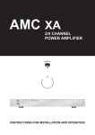
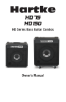
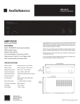
© Nexus Technologies P/L, 2010
S:\Manuals\LC444 Amplifier
Manual\LC444_Instruction_Manual_03_151210.doc
Instruction Manual
Serial Control 4-Zone HiFi Amplifier
Model LC444
© Nexus Technologies P/L, 2010
Client:
Status:
Authorised by:
Comment Closure Date:
Version
1
2
3
4
Date
27 July 2010
19 August 2010
15 Dec 2010
S:\Manuals\LC444 Amplifier
Manual\LC444_Instruction_Manual_03_151210.doc
Document Status
Nexus
Controlled external release
DJA
30 July 2010
Revision History
Changes
Initial Release
Added Bank Set Table
Improved table 1
© Nexus Technologies P/L, 2010
S:\Manuals\LC444 Amplifier
Manual\LC444_Instruction_Manual_03_151210.doc
Table of Contents
1
INTRODUCING THE LC444........................................................................ 4
1.1
Brief Overview ................................................................................................................. 4
1.2
LC444 Front Panel ........................................................................................................... 4
1.3
Amplifier Rear Panel ....................................................................................................... 4
1.4
Amplifier Rear Panel Connections ................................................................................ 5
1.5
Amplifier Rear Panel Configuration Switches .............................................................. 6
1.5.1
Option Switches ......................................................................................................... 6
1.5.2
RTS and DTR Reset Controls: .................................................................................. 7
1.5.3
IR Enable ................................................................................................................... 7
1.5.4
RS232 Loop Termination .......................................................................................... 7
1.5.5
Zone Bank Setting ..................................................................................................... 7
1.6
Amplifier Serial Control .................................................................................................. 8
1.6.1
Control Physical Interface ......................................................................................... 8
1.6.2
Control Electrical Interface ........................................................................................ 8
1.6.3
Control Signaling Interface ........................................................................................ 8
1.7
Table 1: Opcodes supported by the LC444 Amplifier .................................................. 9
1.8
Storage of Settings........................................................................................................ 10
2
STARTUP GUIDE ..................................................................................... 10
APPENDIX A: SPECIFICATIONS ................................................................... 11
APPENDIX B: BANK SETTINGS .................................................................... 12
Leaf 4-Zone Amplifier User Manual
Model LC444
Page 3
Of 14
© Nexus Technologies P/L, 2010
S:\Manuals\LC444 Amplifier
Manual\LC444_Instruction_Manual_03_151210.doc
1 Introducing the LC444
1.1 Brief Overview
The Model LC444 features four independent stereo audio amplifiers, each capable of
selecting one of four sources, in the one enclosure. The amplifier is entirely controlled
by serial RS232 data, either from a host computer or smart home controller. Basic
control is also available from some configurations of Leaf Matrix systems via a suitable
Leaf interface.
The front of the LC444 features only the power LED. All connections; audio signal
sources, speakers, RS232 control and mains power are made at the back of the
LC444. Static configuration switches are also at the rear of the amplifier.
The LC444 is designed for 19” rack mounting, but may be used in a stand free
application.
The LC444 is easy to set up and simple to use. The installer however, must be
experienced in programming similar products and have a thorough understanding of
binary and hexadecimal numbering systems.
1.2 LC444 Front Panel
The LC444 front panel features the power LED. Strictly speaking this is an amplifier
health indicator. It fades in and out in intensity over a five second interval indicating
that all internal operation is correct.
1.3 Amplifier Rear Panel
All connections to the LC444 amplifier; audio signal sources, speakers, RS232 control
and mains power are made at the back of the unit. There are also configuration
switches which are accessible at the rear of the amplifier.
Leaf 4-Zone Amplifier User Manual
Model LC444
Page 4
Of 14
© Nexus Technologies P/L, 2010
S:\Manuals\LC444 Amplifier
Manual\LC444_Instruction_Manual_03_151210.doc
1.4 Amplifier Rear Panel Connections
The LC444 provides the following connections :
Four stereo source inputs with RCA connectors.
Four stereo speaker outputs with modular connectors.
RS232 control input via DB9 female socket wired DCE.
RS232 loop-through output via DB9 male socket wired DTE.
Mains power input via three-pin IEC socket, fuse holder and switch.
The following pictures show the layout of connectors on the rear panel:
Input Sockets
Output Connectors
Serial Control Connectors
IEC Mains Socket, fuse holder and switch
Leaf 4-Zone Amplifier User Manual
Model LC444
Page 5
Of 14
© Nexus Technologies P/L, 2010
S:\Manuals\LC444 Amplifier
Manual\LC444_Instruction_Manual_03_151210.doc
1.5 Amplifier Rear Panel Configuration Switches
The LC444 provides switch settings for the following static parameters:
4 Option Switches
RTS and DTR Reset Controls
IR Enable
RS232 Loop Termination
Zone Bank Setting
1.5.1 Option Switches
The option switches are used to set particular operational variations.
Switch A: No function at this time, reserved for future or special implementation
Switch B: No function at this time, reserved for future or special implementation
Switch C: Enables USB compatibility mode. When a USB to RS232 adaptor is used,
put this switch in the ON (up) position to increase the serial message abort timeout.
When using RS232 derived straight from a standard source, leave this switch in the
OFF (down) position.
Switch D: Enables LAB compatibility mode for when Audio feeding the amplifier is
extracted from a Leaf Matrix system with one or more LAB44 audio breakout units.
When Switch D is ON (up) the LC444 locks the source selection to the zone selection.
That is, the source selected will always be equal to the zone selected.
Ie:
Amplifier Input source 1 to Zone 1
Amplifier Input source 2 to Zone 2
Amplifier Input source 3 to Zone 3
Amplifier Input source 4 to Zone 4
Leaf 4-Zone Amplifier User Manual
Model LC444
Page 6
Of 14
© Nexus Technologies P/L, 2010
S:\Manuals\LC444 Amplifier
Manual\LC444_Instruction_Manual_03_151210.doc
1.5.2 RTS and DTR Reset Controls:
Rear panel configuration switch settings allow RS232 control of the amplifier reset
function by either or both DTR and RTS signals. The reset function may be disabled by
setting both switches to the off position.
1.5.3 IR Enable
Leaf offers an IR Control option as special build only. Putting the rear panel IR Enable
switch in the On position has no effect on standard LC444 Amplifiers.
1.5.4 RS232 Loop Termination
To cater for loop-through control of multiple RS232 Leaf devices, the LC444 provides
an RS232 Out socket for daisy-chaining of devices. Use a 9-pin Male-Female 1:1
standard lead for connection from the host controller and to all other devices in the
chain. Do not use a so-called null-modem cable. The last device in the daisy chain
must have its RS232 Termination switch on. For the LC444, this is done by placing the
RS232 Term switch on the rear panel in the up position.
1.5.5 Zone Bank Setting
The LC444 can be set to respond to any Zone Bank address (in blocks of 4) from
physical Zones 1-4 (default) up to physical Zones 253 -256.
The required Zone Bank is selected by the 2 rotary Zone Bank switches
Refer to the table in appendix B for the required Switch Settings.
Leaf 4-Zone Amplifier User Manual
Model LC444
Page 7
Of 14
© Nexus Technologies P/L, 2010
S:\Manuals\LC444 Amplifier
Manual\LC444_Instruction_Manual_03_151210.doc
1.6 Amplifier Serial Control
The LC444 is designed to be controlled by RS232 signals from equipment such as a
home automation system or other third-party equipment.
1.6.1 Control Physical Interface
The control input to the LC444 is via DB 9 female (socket) connector wired Data
Communications Equipment (DCE):
Pin
Signal
Direction
1
2
3
4
5
6
7
8
9
DCD
TxD
RxD
DTR
Gnd
DSR
RTS
CTS
RI
DCE → DTE
DCE → DTE
DTE → DCE
DTE → DCE
DCE → DTE
DTE → DCE
DCE → DTE
DCE → DTE
Note that:
DTR is looped-back to emulate DSR and DCD.
Neither hardware (RTS/CTS) or software (XON/XOFF) handshake is required
or supported.
1.6.2 Control Electrical Interface
The serial data electrical format is detailed in Appendix A: Specifications.
1.6.3 Control Signaling Interface
Control codes are sent to the LC444 from the PC or other RS232 serial device. The
data is sent in binary (not ASCII) form. The source numbering is physical, that is it
numbers from 1 up. The zone numbering is logical, that is it numbers from 0 up.
Data is sent in packets, with each packet consisting of 3 contiguous bytes:
The first byte is an opcode byte specifying the action to be performed,
the second byte contains additional parameters (most often the source).
the third byte is to determine which zone is to be controlled
i.e. each packet from the controller to the interface is of the format:
Byte
D7
1
2
3
D6
D5
D4
Bit
D3
D2
D1
D0
Opcode
Additional Parameter (usually source *)
Zone to be controlled
* Byte 2 data is used on some commands to specify a value.
For example: Volume set, Treble set, Bass Set.
Leaf 4-Zone Amplifier User Manual
Model LC444
Page 8
Of 14
© Nexus Technologies P/L, 2010
S:\Manuals\LC444 Amplifier
Manual\LC444_Instruction_Manual_03_151210.doc
1.7 Table 1: Opcodes supported by the LC444 Amplifier
Opcodes
Description
Global Commands
Global On
Turn all zones on with the specified source (**)
Global Off
Turn all zones off
Zone Specific Commands
Zone On
Turn the specified zone on with the specified source
Zone Off
Turn the specified zone off
Volume Inc
Increment the specified zone volume 1 step of steps 0-100
Volume Dec
Decrement the specified zone volume 1 step of steps 0-100
Volume Abs Set
Set the specified zone absolute volume to a step value 0-100 (byte 2)
subject to the limitations of Volume Max Set
Volume Max Set
Set maximum permitted zone volume step (0-100)
Volume Max Clear
Clear the maximum permitted zone volume
Treble Inc
Increment the specified zone treble 1 step of steps 0-100
Treble Dec
Decrement the specified zone treble 1 step of steps 0-100
Treble Abs Set
Set the specified zone absolute treble to a step value 0-100 (byte 2)
Treble Flat Set
Set the zone treble flat (equivalent to step 50)
Bass Inc
Increment the specified zone bass 1 step of steps 0-100
Bass Dec
Decrement the specified zone bass 1 step of steps 0-100
Bass Abs Set
Set the specified zone absolute bass to a step value 0-100 (byte 2)
Bass Flat Set
Set the zone bass flat (equivalent to step 50)
Loudness On
Turn the zone loudness on
Loudness Off
Turn the zone loudness off
Mute Deploy
Turn the zone mute on
Mute Cancel
Turn the zone mute off
Mute Toggle
Toggle the zone mute
Query Commands
Query Volume
Query the zone volume setting
Query Bass
Query the zone bass setting
Query Treble
Query the zone treble setting
Query Loudness
Query the zone loudness setting
Query Mute
Query the zone mute setting
Query Zone Aud
Query the zone audio source setting
Query Responses
Return Volume
Return the step value (0-100) of the specified zone volume (Hex0x00-0x64)
Return Bass
Return the step value (0-100) of the specified zone bass
Return Treble
Return the step value (0-100) of the specified zone treble
Return Loudness
Return the zone loudness setting (Hex0x5E(ON) or 0x5F(OFF)
Return Mute
Return the zone mute setting (Hex0x5A(ON) or 0x5B(OFF)
Return Zone Aud
Return the zone audio source setting (Hex0x01-0x04)
** Source selection may be locked to the Zone by Dip Switch D.
Refer to the document Nexus / Leaf Serial Codes for details of binary values of
all opcodes and values declared by Nexus / Leaf.
Leaf 4-Zone Amplifier User Manual
Model LC444
Page 9
Of 14
© Nexus Technologies P/L, 2010
S:\Manuals\LC444 Amplifier
Manual\LC444_Instruction_Manual_03_151210.doc
1.8 Storage of Settings
Non-volatile FLASH memory is used to store all operating parameters. This includes
Zone Source selection and zone volume and tone settings.
It is important to note however, that backup to permanent memory does not happen
immediately after each and every change of any parameter, it only takes place after a
period of 20 seconds of no activity after a change has taken place. Thus it is important
not to power down the unit immediately after making changes to the amplifier settings.
2 Startup Guide
The following steps are required to configure the amplifier for use:
Connect the signal sources (e.g. tuner, CD, DVD etc) to the 4 source inputs on
the back panel.
Connect the speaker leads to the speaker modular sockets supplied and plug
these into the amplifier speaker outputs. Observe correct speaker polarity when
making these connections.
Connect the RS232 lead from the host controller to the Remote Control socket.
Set the RS232 Termination as required.
Set the Zone Bank Minor and Major settings as required to select the base
address for the LC444 in the target system.
Connect the mains lead to the mains supply and plug it into the LC444 IEC
mains socket. Refer to the specifications in the Appendix to check supply
voltage compatibility.
Switch the amplifier on using the switch located above the IEC power socket on
the rear panel.
The LC444 is now ready for use.
Leaf 4-Zone Amplifier User Manual
Model LC444
Page 10
Of 14
© Nexus Technologies P/L, 2010
S:\Manuals\LC444 Amplifier
Manual\LC444_Instruction_Manual_03_151210.doc
Appendix A: Specifications
Parameter
Specification
Output Power Capability
Number of Stereo Output Zones
Load Impedance (per Channel per Zone)
400W (100W per zone)
4
4 to 16 Ohms
Operating Temperature Range
Storage Temperature Range
Operating Humidity Range
Storage Humidity Range
Cooling
0 to 40°C
0 to 90°C
20 to 90% RH Non-condensing
20 to 90% RH Non-condensing
Convection and fan-forced
Number of Stereo (Source) Inputs
Audio Input Connectors
4
Dual RCA Sockets
RS232 Remote Control
Baud Rate
Format
Data format RS232
DB9 Female, wired DCE
9600 Baud
8, N, 1
Byte Non-Inverted
Power Supply
Maximum Supply Current
Power Connector
Fuse Type
220 to 240Vac, 50Hz
3A / 240Vac
3-pin IEC socket
M205 Time-lag 250V~ T2AL
Mounting Clearances
Dimensions (W x D x H)
Weight
1RU above and below amplifier
485 x 300 x 120 (3RU)
6Kg
Leaf 4-Zone Amplifier User Manual
Model LC444
Page 11
Of 14
© Nexus Technologies P/L, 2010
S:\Manuals\LC444 Amplifier
Manual\LC444_Instruction_Manual_03_151210.doc
Appendix B: Bank Settings
Physical
Zone
Range
1-4
5-8
8-12
13-16
17-20
21-24
25-28
29-32
33-36
37-40
41-44
45-48
49-52
53-56
57-60
61-64
65-68
69-72
73-76
77-80
81-84
85-88
89-92
93-96
97-100
101-104
105-108
109-112
113-116
117-120
121-124
125-128
129-132
133-136
137-140
141-144
Leaf 4-Zone Amplifier User Manual
Set Bank Switch Settings
Minor
Major
0
4
8
C
0
4
8
C
0
4
8
C
0
4
8
C
0
4
8
C
0
4
8
C
0
4
8
C
0
4
8
C
0
4
8
C
0
0
0
0
1
1
1
1
2
2
2
2
3
3
3
3
4
4
4
4
5
5
5
5
6
6
6
6
7
7
7
7
8
8
8
8
Model LC444
Page 12
Of 14
© Nexus Technologies P/L, 2010
Physical
Zone
Range
145-148
149-152
153-156
157-160
161-164
165-168
169-172
173-176
177-180
181-184
185-188
189-192
193-196
197-200
201-204
205-208
209-212
213-216
217-220
221-224
225-228
229-232
233-236
237-240
241-244
245-248
249-252
253-256
Leaf 4-Zone Amplifier User Manual
S:\Manuals\LC444 Amplifier
Manual\LC444_Instruction_Manual_03_151210.doc
Set Bank Switch Settings
Minor
Major
0
4
8
C
0
4
8
C
0
4
8
C
0
4
8
C
0
4
8
C
0
4
8
C
0
4
8
C
9
9
9
9
A
A
A
A
B
B
B
B
C
C
C
C
D
D
D
D
E
E
E
E
F
F
F
F
Model LC444
Page 13
Of 14
© Nexus Technologies P/L, 2010
S:\Manuals\LC444 Amplifier
Manual\LC444_Instruction_Manual_03_151210.doc
Leaf Model LC444 Amplifier
Important Safety Information
CAUTION
TO REDUCE THE RISK OF ELECTRIC SHOCK DO NOT REMOVE THE COVER.
NO USER SERVICEABLE PARTS INSIDE.
REFER SERVICING TO QUALIFIED SERVICE PERSONNEL.
FOR CONTINUED PROTECTION AGAINST RISK OF FIRE, REPLACE ONLY WITH THE
CORRECT TYPE OF FUSE.
DISCONNECT SUPPLY CORD BEFORE CHANGING FUSE.
WARNING
SHOCK HAZARD. DO NOT OPEN.
TO REDUCE THE RISK OF FIRE OR ELECTRIC SHOCK DO NOT EXPOSE THIS
APPLIANCE TO RAIN OR MOISTURE.
EQUIPMENT MUST BE CONNECTED TO A MAINS SOCKET OUTLET WITH PROTECTIVE
EARTH CONNECTION.
MAINS LEADS
This appliance is supplied with a non-rewireable mains lead.
Replacement mains leads can be obtained from Nexus Technologies Pty Ltd.
General Safety Instructions
1. Read instructions. Read the safety and operating instructions before operating the
appliance.
2. Retain instructions. Retain the safety and operating instructions for future reference.
3. Heed warnings. Observe all warnings on the appliance and in the operating instructions.
4. Follow instructions. Follow all operating and use instructions.
5. Water and moisture. Do not use the appliance near water, for example near a washbowl,
sink or in a wet basement.
6. Ventilation. Site the appliance so that its location or position does not interfere with its
proper ventilation. For example, the appliance should not be situated close to surfaces that may
block the ventilation openings, or placed in a sealed, unventilated rack that may impede the
flow of air through the ventilation openings.
7. Heat. Site the appliance away from heat sources such as radiators, heaters, stoves, or other
appliances (including other amplifiers) that produce heat.
8. Power sources. Connect the appliance to a power supply only of the type described in the
operating instructions or marked on the appliance.
9. Cleaning. The product should be cleaned only as recommended by the manufacturer.
10. Objects and liquid entry. Do not let objects or liquids fall into the product. Do not expose
the product to dripping or splashing.
Do not place a vessel containing liquid on top of the product.
11. Damage requiring service. The product should be serviced by qualified personnel if:
a) The power cord or plug has been damaged.
b) Objects or liquid have fallen into the product.
c) The product has been exposed to rain.
d) The product does not appear to operate normally or exhibits a marked change in operation.
e) The product has been dropped or the enclosure damaged.
12. Servicing. Do not attempt to service the product beyond that described in the operating
instructions. All other servicing should be referred to qualified service personnel.
Replacing the Fuse in the Mains Socket / Switch Assembly
This appliance is fitted with a replaceable fuse. If the fuse has blown it can be replaced as
follows:
a) Turn off the appliance and remove the power lead.
a) Pull out the fuse cover/carrier.
b) Remove and dispose of the blown fuse.
c) Fit a new fuse into the carrier and push the carrier back into the socket / switch assembly.
Refer to specifications for fuse rating and type.
Fit only the type and rating specified.
Leaf 4-Zone Amplifier User Manual
Model LC444
Page 14
Of 14