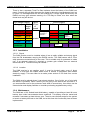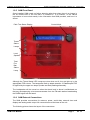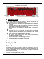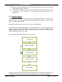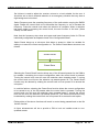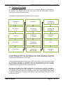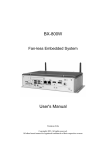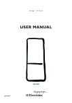
1
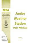
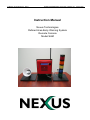
© Nexus Technology P/L, 2010
S:\Manuals\SAM\SAM_Instruction_Manual_01_141010.doc
Instruction Manual
Nexus Technologies
Defined Area Early Warning System
Remote Console
Model SAM
© Nexus Technology P/L, 2010
Client:
Status:
Authorised by:
Comment Closure Date:
Version
1
2
3
4
Date
181010
S:\Manuals\SAM\SAM_Instruction_Manual_01_141010.doc
Document Status
Nexus
Controlled external release
DJA
181010
Revision History
Changes
Initial Release
© Nexus Technology P/L, 2010
S:\Manuals\SAM\SAM_Instruction_Manual_01_141010.doc
Table of Contents
1
INTRODUCING THE SAM........................................................................... 4
1.1
Brief Overview ................................................................................................................. 4
1.2
The Key Concepts ........................................................................................................... 5
1.2.1
Updating your cell ...................................................................................................... 5
1.2.2
The information displayed.......................................................................................... 5
1.2.3
Installation.................................................................................................................. 6
1.2.4
Maintenance .............................................................................................................. 6
1.2.5
SAM Front Panel ....................................................................................................... 7
1.2.6
SAM External Connections ........................................................................................ 7
2
INSTALLATION GUIDE .............................................................................. 8
3
USING THE SAM ........................................................................................ 8
3.1
3.2
3.3
3.4
3.5
User Mode ........................................................................................................................ 8
Installer Mode .................................................................................................................. 9
Configuration Mode ...................................................................................................... 11
Storage of Settings........................................................................................................ 12
Loss of Signal ................................................................................................................ 12
APPENDIX A: RDS .......................................................................................... 13
APPENDIX B: EXTERNAL SIGNALS ............................................................. 14
APPENDIX C: SPECIFICATIONS ................................................................... 15
SAM User Manual
Page 3
Of 15
© Nexus Technology P/L, 2010
S:\Manuals\SAM\SAM_Instruction_Manual_01_141010.doc
1 Introducing the SAM
It is important that the user read and understand this section so that they are aware of
what the system can and cannot do for them. In times of emergency the DAEW can
provide them with critical information about an impending threat, but what actions they
should take in such circumstances are their choice entirely. The user must have a
prepared plan of action – whether to stay and defend or evacuate in a safe and timely
manner.
The DAEW must also not be considered to be one hundred percent reliable. No
system can ever be. The user must understand that the DAEW information, like any
other source of information, can be obsolete, inaccurate or at worst, incorrect. The
DAEW is simply another method of keeping the user informed and should only be
used to supplement not replace existing Internet, free-to-air or subscription media,
telephone, SMS, audible warning system or other form of alert messaging.
1.1 Brief Overview
The Defined Area Early Warning (DAEW) system is aimed at assisting people living in
bushfire prone areas to better protect themselves and make informed and timely
decisions about evacuating or staying with property in the event of fire.
The DAEW system has been designed to provide a means of delivering a
geographically specific threat warning to individuals or groups within high risk areas.
Delivery areas are defined as cells on an arbitrary grid which may be as small as one
kilometre. The system also caters for delivering the same message to an area as big
as a Total Fire Ban district or even the entire state. This enables total fire ban
information or district-wide fire danger ratings to be efficiently broadcast. The DAEW
has been designed primarily as a fire warning system, but there is no reason why the
system cannot be used for other geographically-specific threats such as flood or
tsunami.
Messages consisting of a cell number and threat message codes are electronically
sent to existing free-to-air FM radio stations for transmission. The system uses the FM
Radio Data Service (RDS) to deliver the threat message information. These
transmissions do not interfere with normal audio content.
The specially designed radio receiver (codenamed SAM) is used to decode and
display the messages. SAM is a prototype radio receiver with a 24 hour battery
backup, a text display, visual threat display and an audio alert. SAM is also able to
control external devices such as sprinkler systems or rotate automated Fire Danger
Rating Signs and is able to be solar powered.
The latest threat message for the receiver‟s cell remains on display, meaning that the
user need only check the radio when able or convenient instead of having to listen at
specific times.
It is important to note that SAM is only a prototype. It has been produced to
demonstrate the core concepts of the DAEW system. It may be obvious that large
amounts of money have not been spent on making it as sleek and stylish as an
iPhone, indeed R&D has been solely devoted to making a robust and simple product
SAM User Manual
Page 4
Of 15
© Nexus Technology P/L, 2010
S:\Manuals\SAM\SAM_Instruction_Manual_01_141010.doc
that fulfils the needs that drove the design requirements in the first place. There is
much more that could be done within the existing design scope with just software
changes and it is this functionality that is under examination in this trial.
There are several menu items that have no meaning, do not function or make no
difference in operation. These are „stubs‟ of functions that are either redundant, still
under development or have yet to be implemented. Please approach any aberrant
operation of these items with a little bit of patience and understanding.
1.2 The Key Concepts
1.2.1 Updating your cell
The DAEW transmits threat information to all cells in the coverage area all the time. As
the information is broadcast by a free-to-air FM station, there is no limit on the number
of receivers and no possibility of extra traffic overloading the system in emergency. All
that is required is that the SAM receiver has good signal strength from the transmitter
site. The SAM listens to all the DAEW messages transmitted, but only displays the
threat codes for the cell it is programmed for.
The amount of information that the RDS subsystem can transmit is not without
bounds. There is not a lot of „bandwidth‟ available, so the DAEW information is quite
succinct to keep update times or latency as low as possible. Realistically, it can take a
couple of minutes to update all cells covered by a particular FM radio station if all cells
are at the same threat level. Such a case isn‟t a problem when the threat level is the
normal, non-critical one, but becomes more important when the threat is not trivial.
Currently all cells are given equal priority, but in future, a system with dynamic priority
allocation would update cells at higher threat levels more frequently than those at
lower levels.
At installation time the SAM will be assigned a cell identification code and this is stored
in permanent memory. The SAM must remain in the cell it has been programmed for
or else the information it delivers may not be accurate. Moving the SAM or changing
its cell identification could render the device useless or worse to give information that
is not accurate for where the receiver is physically located.
The final consideration is that the DAEW can only deliver the information that is fed to
it. If this information is inaccurate or stale then the DAEW cannot improve it.
1.2.2 The information displayed
The SAM delivers the threat information for the cell it resides in the following ways
In plain text on the LCD display
On the colour-coded LED threat „tree‟
As audible tones from the loudspeaker
Via optional external threat display and or siren
The nomenclature and colours are harmonised with the current Fire Danger Rating
(FDR) as reproduced in the following table.
SAM User Manual
Page 5
Of 15
© Nexus Technology P/L, 2010
S:\Manuals\SAM\SAM_Instruction_Manual_01_141010.doc
There is also a separate Total Fire Ban Indicator down the bottom of the SAM front
panel. Currently this will light whenever the threat is above the Low-Moderate level, but
in future it is envisaged that this will be enabled by a unique signal delivered by the
DAEW and may give advance warning of a TFB day to follow, at a time when the
threat level may still be low.
Fire Danger Rating
Flame
Ht/Rate
Category
Fire
of
Danger
Index Spread
Catastrophic 100+
Extreme
75-99
Severe
50-74
Very High
25-49 Variable
High
12-24
Low0-11
moderate
<2 Hrs
Time to Impact
2-6Hrs
6-24Hrs
Emergency
Warning +
SEWS
24+Hrs
Watch
and Act
Advice
1.2.3 Installation
1.2.3.1 Signal
The SAM receiver must be installed where it has a totally reliable and strong signal
from the FM broadcaster carrying the DAEW service. The SAM comes with a 70cm
whip antenna mounted directly to the case. This is suitable only for protected or inside
use. If an external antenna is required or greater gain needed then an external
directional FM or TV antenna may be needed.
1.2.3.2 Location
The SAM receiver is not weather proof. It must be located under cover of direct
weather. It must also be located where there is access to permanent and reliable
electricity supply. This can either be a mains power socket or DC feed from a solar
installation.
The SAM must be placed where it can attract attention. Out of sight, out of mind with
this device is pointless. Place it where you are going to be able to see and hear it. If
you need another one for the outhouse, back shed or second story, then either use the
external siren and display facilities or consider purchasing supplementary unit(s).
1.2.4 Maintenance
The SAM has a 12V Sealed Lead-Acid battery, capable of providing at least 24 hours
backup time under low-moderate threat conditions. This battery must be tested and
renewed if necessary at least twice a year. There is some limited scope for the system
to launch a battery self-test to the SAM, but at this time this functionality has not been
implemented.
SAM User Manual
Page 6
Of 15
© Nexus Technology P/L, 2010
S:\Manuals\SAM\SAM_Instruction_Manual_01_141010.doc
1.2.5 SAM Front Panel
Once installed, SAM needs no further attention other than when there is a change in
the fire threat level to the cell that it is installed in. It is however, of the utmost
importance to know what exactly is the information that SAM provides, and how it is
shown.
Plain Text Status Display
Control Knob
Threat
Status
Lamps
LoudSpeaker
Lamps
Total
Fire
Ban
Status
Lamp
Although the Threat Status LED Lamps are clear when not lit, they do light up in the
appropriate FDR colours. The lamps also flash to attract attention. A Catastrophic FDR
is signified by the upper two lamps (Amber and Red) flashing alternately.
The loudspeaker will be turned on when the threat level is above Low-Moderate so
that any accompanying voice announcements from the FM radio station broadcasting
the DAEW signal can be heard.
1.2.6 SAM External Connections
The SAM provides connections for antenna, power, serial data, external siren and
display and analog audio output. All connectors are at the base of the unit.
The following picture shows the layout of the connectors:
SAM User Manual
Page 7
Of 15
© Nexus Technology P/L, 2010
S:\Manuals\SAM\SAM_Instruction_Manual_01_141010.doc
External Status Lamp Connections
Power Input
External Relay Connections
Mono Audio Output
External LoudSpeaker or Siren
RS232 Serial Data
2 Installation Guide
For the installer familiar with the basic operation of the SAM menu system, the
following steps are required to configure the unit for use:
Remove 8 countersunk M3 screws top and bottom and remove the rear section
of the case.
Connect the battery flying lead to the connector on the back of the PCB paying
attention that the correct polarity has been observed.
Set the volume and tone signalling internal dipswitch options as requested by
the user.
Refit the rear case section and secure it with the screws removed earlier.
Connect the plug pack to the mains supply, plug the DC lead into the SAM and
the antenna lead to the antenna socket. Connect serial, external relay, external
lamp and external siren as required.
Set the cell identification code to the assigned cell number.
Set the tuner to the frequency of the station broadcasting the DAEW
information and store this to preset 1.
Set FM channel volume to the level requested by the user.
Verify that the SAM is decoding the DAEW signal and the threat status is
flashing green and the LCD is displaying Low-Moderate.
The SAM is now ready for use.
3 Using the SAM
3.1 User Mode
The SAM has no real use for the end user except when an emergency exists. The
user can check that the SAM is operational by pressing the control knob in, which will
turn on the audio amplifier and send the received audio signal to the internal (and
external if fitted) loudspeaker.
Future user-accessible enhancements will include:
SAM User Manual
Page 8
Of 15
© Nexus Technology P/L, 2010
S:\Manuals\SAM\SAM_Instruction_Manual_01_141010.doc
Extensive self-test diagnostic routines that will allow the user to verify that the
SAM is operating as it should.
The ability to monitor any other cell to determine the threat in that cell. The
primary use of this function is to evaluate the best escape route in an
emergency.
3.2 Installer Mode
Installer mode is accessed from User Mode by pressing the selection knob 4 times
within 1 Second. The display will show the message “Exit Installer Y” if this process
has been performed correctly.
Rotate the control knob ccw and press it to enter Installer Mode.
In Installer and Configuration Modes, a 30 second inactivity timer is running and will
result in operation being returned to User Mode if there is no front panel control
actions within this time. Note that the SAM continues to receive and decode any
DAEW messages whilst in this mode.
Installer Mode features the following menu structure:
Set Volume
Select Frequency
Select Preset
Select Config
Exit Installer
Using the Installer Mode functions as described allows the installer to quickly set up
the SAM at the user‟s premises; adjust the volume and set up the station presets.
SAM User Manual
Page 9
Of 15
© Nexus Technology P/L, 2010
S:\Manuals\SAM\SAM_Instruction_Manual_01_141010.doc
Set Volume is used to adjust the receiver volume to a level suitable for the user. It
should be set so that it demands attention in an emergency situation that may have a
high background noise level.
Select Frequency sets the operating frequency of the radio station carrying the DAEW
signal. Rotate the control knob ccw to decrease the frequency or cw to increase the
frequency. Press the control knob when the selection is complete. When a selection
has been made by pressing the control knob, the next function in the tree (Select
Preset) is made active.
Note that the frequency step sizes and upper and lower frequency limits for FM are
individually configurable as separate items in the Configuration Menu.
Select Preset brings up a sub-menu that allows a preset to either be recalled for
editing or to save the current configuration to. The Select Preset Menu structure is as
follows:
Preset Recall
Preset Save
Selecting the Preset Recall function allows any of the 20 saved presets for the SAM to
be recalled, overwriting the current configuration when the control knob is pressed.
Turning the control knob ccw will move the selection down towards preset 1, turning
the control knob cw will move the selection up towards preset 20. The Preset Recall
function may be aborted by rotating the control knob cw from preset 20 to access the
exit option.
In a similar fashion, selecting the Preset Save function allows the current configuration
to be saved to any of the 20 presets when the control knob is pressed. Turning the
control knob ccw will move the selection down towards preset 1, turning the control
knob cw will move the selection up towards preset 20. The Preset Save function may
be aborted by rotating the control knob cw from preset 20 to access the exit option.
Exiting either of the above functions will result in control being passed back to the Set
Volume function.
A future enhancement will be to provide a PIN to lock out installer mode to nonqualified access.
SAM User Manual
Page 10
Of 15
© Nexus Technology P/L, 2010
S:\Manuals\SAM\SAM_Instruction_Manual_01_141010.doc
3.3 Configuration Mode
The Configuration Mode is used to set up the more basic operational parameters of
the receiver. The installer should only ever have to use the configuration functions
once, usually at the initial setup stage.
Configuration Mode features the following menu structure:
Set Brightness
(1 – 8)
Audio Timer
Set FMin AM
( Step AM kHz)
Set Contrast
(1 – 8)
Set Step FM
(1 – 10 x 10kHz)
Set FMax AM
(Step AM kHz)
Set Mute
Set Step AM
(1 – 9 x 1kHz)
Preset Scan
(Y, N)
Set Pri Zone
Set FMin FM
(Step FM MHz)
Null 2
Set Sec Zone
Set FMax FM
(Step FM MHz)
Exit Config?
(Y, N)
Of the available functions only Set Brightness, Set Contrast and Set Pri Zone should
be used. Accessing any of the other functions may cause unpredictable results and
possible erroneous operation of the SAM.
Unless otherwise described, exiting one function will result in the next function down
the tree being accessed. For example, once the Set Brightness function has been
used to adjust the display brightness, exiting this function will result in the installer
being prompted to access the Set Contrast function.
Set Brightness allows the display brightness to be altered to suit the installation.
Rotating the control knob ccw to a setting of 1 will result in the backlight being almost
off, rotating the control knob cw to a setting of 8 will result in the backlight being driven
to maximum brightness. Press the control knob to make the selection and return to the
configuration menu.
SAM User Manual
Page 11
Of 15
© Nexus Technology P/L, 2010
S:\Manuals\SAM\SAM_Instruction_Manual_01_141010.doc
Set Contrast is used to adjust the contrast of the display characters with respect to the
background. This also has an effect on the viewing angle. Rotate the control knob ccw
towards setting of 1 or cw towards a setting of 8 to achieve maximum contrast at the
normal viewing angle. Press the control knob to make the selection and return to the
configuration menu.
Set Pri Zone is used to select the cell code that the SAM is zoned for. At this stage of
development the range of cells is 0 through 15. Rotate the control knob ccw towards
the minimum setting of 0 or cw towards a maximum setting of 15. Press the control
knob to make the selection and return to the configuration menu.
3.4 Storage of Settings
Non-volatile FLASH memory is used to store all operating parameters. This includes
all items that are able to be setup in the Installer Menu as well as all items in the
Configuration Menu.
It is important to note however, that backup to permanent memory does not happen
immediately after each and every change of any parameter, it only takes place after a
period of 20 seconds of no activity after a change has taken place. Thus it is important
not to power down the unit immediately after making changes to the SAM installer or
configuration settings.
3.5 Loss of Signal
Should the SAM not be able to decode a DAEW message with its cell code within a
preset time period, it will show “No Cell Message” on the display.
If the SAM experiences loss of valid DAEW signal when not at the Low-moderate level
it will presume the worst and autonomously escalate the threat level with successively
shorter intervals.
[Ends]
SAM User Manual
Page 12
Of 15
© Nexus Technology P/L, 2010
S:\Manuals\SAM\SAM_Instruction_Manual_01_141010.doc
Appendix A: RDS
The SAM decodes the Group 9A codes of RDS Blocks C and D. This is the
Emergency Warning System (EWS) allocation of the RDS standard. If you have a
receiver capable of displaying RDS messages and it displays text other than the
normal data transmitted by the station during the DAEW operation, please advise the
station.
SAM User Manual
Page 13
Of 15
© Nexus Technology P/L, 2010
S:\Manuals\SAM\SAM_Instruction_Manual_01_141010.doc
Appendix B: External Signals
The SAM makes available some signals for external use. These signals are:
RS232 raw RDS DAEW data for external processing
Line level audio for smart home emergency annunciation
Open-collector drive for an external threat display
Speaker drive out for an external siren or speaker
Uncommitted relay contacts for an emergency sprinkler system or other similar
device.
The specifications for each of these signals or signal groups is contained in the
Specifications Appendix, but it is worth discussing the relay contact function a bit
further here.
There are two sets of relay contacts, separately energized. Both sets have the
Common, Normally Open and Normally Closed contacts bought out to their respective
connectors. Relay A is driven whenever the threat level is above the Low-Moderate
level. Relay B is driven whenever the threat level is at the Catastrophic level.
There is no prescribed or recommended implementation for these relays as the variety
of end uses is virtually limitless.
A future enhancement will be to provide customizable trigger thresholds for these
functions.
SAM User Manual
Page 14
Of 15
© Nexus Technology P/L, 2010
S:\Manuals\SAM\SAM_Instruction_Manual_01_141010.doc
Appendix C: Specifications
Parameter
Specification
Control
Text Display
Text Display Controls
Status Display
Bidirectional Rotary Control, Push-to-Select
16 characters x 1 line LCD, backlit blue
Adjustable Brightness and Contrast
6 x high-brightness LEDs
Number of Presets
Tuning Range (FM)
Tuning Step Size (FM)
20
Programmable: 88.00 to 108.00 MHz default
Programmable: 10 to 100kHz
Antenna Input
Audio Output
RS232 Serial Data
F-Type Socket
Single (mono) RCA Socket
DB9 Female, wired DCE
Baud Rate
Format
Data format RS232
9600 Baud
8, N, 1
Binary
Relay Contacts
External Lamp Drive
External Speaker Drive
No/C/NC, 24V DC max, 1Amp max
Open Collector, 12VDC max, 500mA max.
7W, 4Ω minimum
Power Requirements
Power Connector
10 to 35V dc, 1 Amp
2.1mm DC socket, centre positive
Dimensions (W x D x H)
Weight
210 x 210 x 70
2.35kG (without antenna)
SAM User Manual
Page 15
Of 15