1
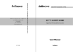
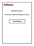
PANEL DESCRIPTION
N3752T/R-ADBE&N3552T/R-ADBE
(The interface definition is the same with IP series)
PWR
PWR
Power on indicator (red)
OP
Optical port, FC or ST
Optical link loss indicator (red)
Chassis GND
Earthing for surge protection
Video input/output, 75ohm, 1Vp-p
20-pin terminal block connector
CH1
Video present indicator (green)
}
}
}
}
1
2
Audio interface, CH 1
See table 1 for detailed pin
definition
Audio receiving indicator (green)
3
4
CH2
Audio transmitting indicator (green)
5
6
7
RS232 output indicator (green)
8
RS232 data interface, CH 2
6#: Out
7#: GND
8#: In
9#: GND
10#: GND
9
RS232 input indicator (green)
10
11
12
13
DIP selectable RS422/
RS485 data interface, CH 3
See table 4 for detailed pin
definition
Data active indicator (green)
Data active indicator (green)
14
15
16
Contact closure active indicator (green)
17
18
Contact closure data interface, CH 4
See table 5 for detailed pin definition
Contact closure active indicator (green)
19
20
Figure 6. N3752T/R-ADBE&N3552T/R-ADBE
11