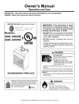
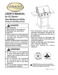
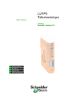
1
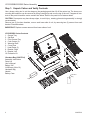
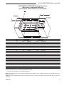
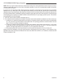
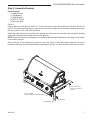
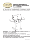
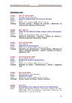
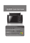
VCS325SSBI Series and VCS525SSBI Series
Assembly Procedures
Model VCS525SSBI Shown
Tools Required: Knife or scissors, Phillips or Robertson (square head) screwdriver.
WARNING: Some parts may have sharp edges; to avoid injury, wearing gloves during assembly, lifting or moving the grill is recommended. Protective eyewear and long sleeves are also
strongly recommended.
CAUTION: This grill is intended ONLY to be built into an enclosure.
CAUTION: The assembly of this grill requires two (2) people.
30007230 10/14 Rev. 1 En
VCS325SSBI/525SSBI Series Assembly
Step 1: Unpack Carton and Verify Contents
Use a sharp cutting tool to cut the straps on the packaging and then lift off the carton top. The sleeve surrounding the barbecue can be removed by lifting it straight up and over the top of the unit. Compare all contents to the parts list and the carton content lists below. Refer to the parts list for fastener detail.
CAUTION: Some parts may have sharp edges; to avoid injury, wearing gloves during assembly is strongly
recommended.
Remove two (2) tie-down brackets, one on each lower side of unit, by removing two (2) screws from each
bracket. Discard brackets.
IMPORTANT: Replace screws removed from lower sides of unit.
VCS325SSBI Carton Contents
1. Grease Tray
2. Spit Rod
3. Front Grease Tray
4. Cook Grates (2)
5. Warming Rack
6. Cover Rear
7. Heat Plates (3)
8. Bracket, Right
9. Bracket, Left
10. Rotisserie Kit
4
9
6
1
Literature Bag (30007234)
Assembly Instructions
Parts List
User’s Manual
Battery “AA”
Lid Bumper (Set of 6)
Hardware Bag
Handle
Battery Case
2
3
8
5
Literature
Bag
10
7
2
30007230
VCS325SSBI/525SSBI Series Assembly
Step 1: Unpack Carton and Verify Contents (continued)
4
9
1
8
2
3
Literature Bag
5
6
7
10
VCS525SSBI Carton Contents
Literature Bag (30007234)
1. Grease Tray
2. Spit Rod
3. Front Grease Tray
4. Cook Grates (4)
5. Warming Rack
6. Cover Rear
7. Heat Plates (5)
8. Bracket Right
9. Bracket Left
10. Rotisserie Kit
Assembly Instructions
Parts List
User’s Manual
Battery “AA”
Lid Bumper (Set of 6)
Hardware Bag
Handle
Battery Case
30007230
3
VCS325SSBI/525SSBI Series Assembly
VCS325SSBI / VCS525SSBI Framing Dimensions
When Using Noncombustible Materials
Q
Q
A
Drain Holes
(2" diameter)
O
J
B
K
L
Q
M
Drain Holes
(2" diameter)
P
F
C
E
D
G
H
I
Ref.
A
B
C
D
E
F
G
H
I
J*
K*
L
M*
N
O
P*
Q**
VCS325SSBI
311⁄2"
(800 mm)
24"
(610 mm)
93⁄8"
(239 mm)
311⁄16"
(78 mm)
3"
(76 mm)
2"
(51 mm)
3
4 ⁄4"
(120 mm)
183⁄4"
(476 mm)
283⁄4"
(730 mm)
5
12 ⁄8"
(321 mm)
181⁄4"
(464 mm)
10"
(254 mm)
31⁄2"
(89 mm) Min.
4"
(102 mm) Min.
4"
(102 mm) Min.
21⁄2"
(64 mm) Min.
36"
(914 mm)
N
B332a
VCS525SSBI
431⁄2"
(1105 mm)
24"
(610 mm)
93⁄8"
(239 mm)
11
3 ⁄16"
(78 mm)
3"
(76 mm)
2"
(51 mm)
3
4 ⁄4"
(120 mm)
183⁄4"
(476 mm)
38"
(965 mm)
125⁄8"
(321 mm)
181⁄4"
(464 mm)
10"
(254 mm)
31⁄2"
(89 mm) Min.
4"
(102 mm) Min.
4"
(102 mm) Min.
21⁄2"
(64 mm) Min.
36"
(914 mm)
*Applies if optional side burner Model VCSSBIB will be installed.
** Clearance from grill lid/hood to combustible materials.
NOTE: If the optional side sear burner Model VCSSBIE will be installed, refer to installation instructions suppied with burner kit for
framing dimensions.
NOTE: If the grill is installed directly under a combustible overhang or ceiling, the ceiling must be at least 38" (965 mm) above the
countertop.
4
30007230
VCS325SSBI/525SSBI Series Assembly
VCS325SSBI / VCS525SSBI Framing Dimensions
When Using Combustible Materials
(ZC Insulated Jacket Required for Installation)
W
W
Drain Holes
(2" diameter)
Drain Holes
(2" diameter)
O
A
W
J
V
B
K
L
V
M
V
P
T
U
C
S
S
E
D
G
F
CL
H
I
Ref.
A
B
C
D
E
F
G
H*
I
J
K
L
M
N
O
P
S
T
U
V
W**
VCS325SSBI
335⁄16"
(846 mm)
245⁄8"
(626 mm)
111⁄8"
(283 mm)
(78 mm)
31⁄16"
3"
(76 mm)
2"
(51 mm)
3"
(76 mm)
183⁄4"
(476 mm)
(730 mm)
283⁄4"
125⁄8"
(321 mm)
181⁄4"
(464 mm)
10"
(254 mm)
31⁄2"
(89 mm) Min.
4"
(102 mm) Min.
4"
(102 mm) Min.
21⁄2"
(64 mm) Min.
97⁄8"
(250 mm)
3"
(76 mm)
4"
(102 mm)
515⁄16"
(150 mm)
36"
(914 mm)
N
B333a
VCS525SSBI
455⁄16"
(1153 mm)
245⁄8"
(626 mm)
111⁄8"
(283 mm)
31⁄16"
(78 mm)
3"
(76 mm)
2"
(51 mm)
3"
(76 mm)
183⁄4"
(476 mm)
38"
(965 mm)
125⁄8"
(321 mm)
181⁄4"
(464 mm)
10"
(254 mm)
31⁄2"
(89 mm) Min.
4"
(102 mm) Min.
4"
(102 mm) Min.
21⁄2"
(64 mm) Min.
1313⁄16"
(350 mm)
3"
(76 mm)
4"
(102 mm)
515⁄16"
(150 mm)
36"
(914 mm)
*Applies if optional side burner Model VCSSBIB will be installed.
**** Clearance from grill lid/hood to combustible materials.
NOTE: If the optional side sear burner Model VCSSBIE will be installed, refer to installation instructions suppied with burner kit for
framing dimensions.
NOTE: If the grill is installed directly under a combustible overhang or ceiling, the ceiling must be at least 38" (965 mm) above the
countertop.
30007230
5
VCS325SSBI/525SSBI Series Assembly
NOTE: Ensure your grill enclosure has been constructed according to the exact specifications shown in Figure 2. If the enclosure is constructed of wood or other similar combustible materials, the use of the insulated jacket Model VCS301SSIJ
or VCS501SSIJ is required.
If you have an LP model with a 20lb cylinder stored in the enclosure, ensure there are at least two (2) air ventilation
openings of 10 sq. inches (64.5 cm2) 180 degrees apart and they are level with the cylinder valve. Another two (2)
openings with the same dimensions and distance are required to be level with the base of the cylinder. An enclosure for
an LP gas cylinder shall be ventilated by openings at both the upper and lower levels of the enclosure. The effectiveness
of the opening(s) for purposes of ventilation shall be determined with the LP gas supply cylinder in place. This shall be
accompanied by one of the following:
a. One side of the enclosure shall be completely open; or
b. For a cylinder enclosure having four (4) sides, a top and a bottom and intended for installation in a built-in enclosure:
1. At least one (1) ventilation opening shall be provided on the exposed exterior side of the enclosure located within
5 in. (127 mm) of the top of the enclosure and unobstructed. The opening(s) shall have a total free area of not less
than 1 in2/lb (14.2 cm2/kg) of stored fuel capacity.
2. At least one ventilation opening shall be provide don the exposed, exterior side of the enclosure 1 in (25.4 mm)
or less from the floor level and shall have a total free area of not less than 1/2 in2/lb (7.1 cm /kg) of stored fuel
capacity. The upper edge shall be no more than 5 in (127 mm) above the floor level.
3. Every opening shall have a minimum dimension so as to permit the entrance of a 1/8 in (3.2 mm) rod.
Always confirm the installation of this grill conforms with the requirements of all local codes or, in the absence of any
applicable local codes, with either the National Fuel Gas Code, ANSI Z223.1/NFPA 54, or CSA B149.1, Natural Gas and
Propane Installation Code.
6
30007230
VCS325SSBI/525SSBI Series Assembly
Step 2: Assemble Brackets
Parts Required:
(1) Main Grill Unit
(1) Left Bracket
(1) Right Bracket
(4) #10 x 1/2" Bolts
(4) #10 Lock Nuts
Figure 1
Prop up the front of the grill unit on a 2" or 3" block of wood or some other similar item. Remove the two (2)
1/4-20 x 3/8" bolts located at the top, right corner on the left and right side of the base assembly and loosen
the two (2) front 1/4-20 x 3/8" bolts as shown.
Attach the right bracket to the grill base by aligning the holes over the loosened bolts and gently pushing
down on the bracket until the bolts settle into the grooves.
NOTE: Ensure the bottom of the flanges on the left and right brackets slide between the flange of the bottom
cover and the console.
Secure the rear of the brackets to the grill unit using the 1/4-20 x 3/8" bolts initially removed. Secure the
brackets to the lower, front of the grill body by inserting two (2) #10 x 1/2" bolts and two (2) #10 nuts as shown.
Figure 1
B517
1/4-20 x 3/8" Screw
(remove from base assembly)
1/4-20 x 3/8" Bolt
(remove half way from base assembly)
#10 Bolts
Right Bracket
30007230
7
VCS325SSBI/525SSBI Series Assembly
Step 3: Assemble the Rear Panel
Parts Required:
(1) Rear Panel
(1) Back Flange
(4) Self-tapping Screws
Figure 2
Attach the back flange of the rear panel to the grill base with two (2) self-tapping screws.
Fasten the ends of the rear panel to the left and right brackets with two (2) self-tapping screws.
Figure 2
Rear Panel
B363
Self-tapping Screws
8
30007230
VCS325SSBI/525SSBI Series Assembly
Step 4: Assemble the Grease Tray Front and Handle
Parts Required:
(1) Grease Tray Front
(1) Handle (with screws)
(2) #10 Bolts
(2) #10 Nuts
Figure 3
Remove the grease tray from the front of the grill base (below the control console). Remove the protective
plastic from the grease tray front. Attach the grease tray front to the front lip of the grease tray with two (2)
#10 bolts and tighten using two (2) #10 nuts.
Attach the handle to the tray with the two (2) screws supplied with the handle.
NOTE: Do not reinsert the grease tray into the grill base at this time.
SERVICE NOTE: Due to the shallow depth of the grease tray, ensure it is cleaned frequently to avoid a possible grease fire.
Figure 3
Grease Tray
#10 Nuts
Handle Hardware
Grease Tray Front
Handle
B256
#10 Bolts
30007230
9
VCS325SSBI/525SSBI Series Assembly
Step 5: Install Backlighting Batteries and Battery Case into Battery Holder
Bracket
Parts Required:
(1) Battery Case
(8) ‘AA’ Batteries
NOTE: Eight (8) ‘AA’ batteries are required for all grill models. (Not included)
Figure 4
Install eight (8) batteries into supplied battery case, taking care of correct polarity.
The battery holder bracket and wire connector are behind the lower left side of the console panel just below
the left control knob.
The battery holder bracket is hinged on its right side. Reaching under the console with four (4) fingers, push
the battery holder bracket’s left side back.
Find the nearby wire connector and snap onto battery case. Slide battery case into battery holder bracket.
Pull bracket forward to original position. Secure any dangling wires.
WARNING: Replacing the battery incorrectly might result in an explosion. Replace the battery only with the
same or equivalent type recommended by the manufacturer. Dispose of used batteries according to your
local environmental guidelines.
Figure 4
10
Battery case and holder bracket shown removed
from console panel for clarity.
30007230
VCS325SSBI/525SSBI Series Assembly
Step 6: Assemble the Grill Unit to the Enclosure
NOTE: This step should be performed by two (2) persons wearing gloves.
Figure 5
Before positioning the grill unit into the prepared enclosure or insulated jacket, depending on the available
access, it may be necessary to temporarily disconnect the LP regulator or Natural Gas connector hose from
the steel flex line.
Carefully position the grill unit into the opening from the front and raised slightly, while ensuring the gas feed
tubing is fed through the hole provided in the bottom of the enclosure opening. Push the unit back into its final
position and check for proper fit.
Reattach the LP regulator or Natural Gas connector hose if it was removed and check all connections for
leaks. Reinsert the grease tray into its place.
CAUTION: The end of the steel flex line should be clamped to the surrounding structure to prevent excessive
movement.
CAUTION: Do not turn on the grill unit until after performing a leak check at all connection points and fittings.
Use a spray solution of 50% dish soap and 50% water onto all connection points and fittings. Formation of
bubbles indicates air leaks.
Figure 5
B518
30007230
11
VCS325SSBI/525SSBI Series Assembly
Step 7: Install Internal Components
Parts Required:
VCS325SSBI
VCS525SSBI
(3) Sear Plates
(5) Sear Plates
(2) Cooking Grates
(4) Cooking Grates
(1) Warming Rack
(1) Warming Rack
(1) Smoker Box (Optional) (1) Smoker Box (Optional)
Figures 6 & 7
Carefully place each of the sear plates side by side inside the grill by making sure the semicircular finger
groove is facing toward the back of the grill. Do the same with the cooking grates, making sure the finger
groove is facing toward the front of the grill. Set the warming rack into the supports located on either side of
the rear lid.
If using the smoker box, place the assembly on any sear plate by laying the bracket over the sear plate so
the ‘z’ ends of the bracket fit into the ‘z’ slots of the sear plate. Slide the smoker box assembly back into the
locked position. (Fig. 7) Continue placing the remaining sear plates. The smoker box may be left in place
when not being used. CAUTION: Only add wood chips to the smoker box when grill is cool.
Figure 6
Sear Plates
Warming Rack
Cooking Grates
Finger Hole
Finger Hole
Figure 7
‘Z’ End
Smoker Box
B362
Sear Plate
B396a
12
30007230
VCS325SSBI/525SSBI Series Assembly
Cooking Tips - Smoker Box
• To produce more smoke and prevent fast burning, pre-soak the wood chips in a separate
•
•
•
•
•
30007230
bowl of water for at least 20 minutes.
To add wood chips before cooking, fill the smoker box with your choice of flavored chips
(remove wood chips from water first). The amount and type of wood you use is entirely up
to you. Once the box is filled with the desired amount, close the lid and place the cooking
grids in the proper position on the grill.
Tips: Small wood chips work best inside the wood chip box.
Allow grill to heat up before placing your food on the grill. This will allow time for the wood
chips to begin to smoke.
Do not use resinous woods such as pine or plywood. These will produce an unpleasant
flavor.
Do not try to add more wood chips while cooking. It is recommended that you allow grill to
cool before replacing wood chips or handling the cooking grates which may still be hot.
13
149 Cleveland Drive • Paris, Kentucky 40361
www.vermontcastingsgroup.com