1
ORBITER User Manual
Copyright (c) 2000-2005 Martin Schweiger
16 January 2005
Orbiter home: www.medphys.ucl.ac.uk/~martins/orbit/orbit.html or www.orbitersim.com
Copyright
The ORBITER software, documentation and the content on the ORBITER website is copyright 2000-2005 by Martin Schweiger.
ORBITER is free software in the sense that you are free to download, copy and redistribute it
for personal and non-commerical purposes, provided that the copyright notice is retained in
the copy. You are not allowed to charge a fee for the software without the consent of the
author other than that to cover the cost of the distribution. If a fee is charged it must be made
clear to the purchaser that the software is freeware and that the fee is to cover the distributor's costs of providing the software. Selling ORBITER or parts of it or bundling it into a commercial product or using ORBITER to promote a commercial product without the author’s
consent is an infringement of the author’s copyrights.
You are not allowed to modify the Orbiter binary code or the documentation distributed with
the Orbiter software package. You are however allowed to distribute modifications to configuration scripts, meshes, or the sample source codes in the Orbitersdk\samples folder, provided
that you make it clear to the recipients that you have made such modifications.
ORBITER is not in the public domain: it is the intellectual property of Martin Schweiger.
Disclaimer
The ORBITER software is provided as is without any warranty of any kind. To the maximum
extent permitted by applicable law, Martin Schweiger further disclaims all warranties, including without limitation any implied or stated warranties of merchantability, fitness for a particular purpose, and noninfringement. The entire risk arising out of the use or performance of this
product and documentation remains with recipient. To the maximum extent permitted by applicable law, in no event shall program ORBITER or its suppliers be liable for any consequential, incidental, direct, indirect, special, punitive, recursive, or other damages whatsoever (including, without limitation, damages for loss of business profits, business interruption, loss of
business information, personal injury, disruption of family life, or other pecuniary loss) arising
out of this agreement or the use of or inability to use the product, even if program ORBITER
has been advised of the possibility of such damages. Because some states/jurisdictions do
not allow the exclusion or limitation of liability of consequential or incidental damages, the
above limitation may not apply to the recipient.
ORBITER User Manual (c) 2000-2005 Martin Schweiger
1
Contents
1
INTRODUCTION ............................................................................................................. 4
2
2.1
2.2
2.3
2.4
INSTALLATION............................................................................................................... 5
Hardware requirements ................................................................................................... 5
Download ......................................................................................................................... 5
Installation........................................................................................................................ 5
Uninstall ........................................................................................................................... 6
3
3.1
3.2
3.3
3.4
3.5
3.6
THE LAUNCHPAD .......................................................................................................... 7
Scenario tab..................................................................................................................... 7
Parameters tab ................................................................................................................ 8
Visual effects tab............................................................................................................ 10
Modules tab ................................................................................................................... 11
Video tab........................................................................................................................ 12
Joystick tab .................................................................................................................... 13
4
QUICKSTART ............................................................................................................... 14
5
GETTING HELP ............................................................................................................ 19
6
6.1
6.2
6.3
6.4
6.5
KEYBOARD INTERFACE............................................................................................. 20
General .......................................................................................................................... 20
Spacecraft controls ........................................................................................................ 21
External camera views................................................................................................... 22
Internal (cockpit) view .................................................................................................... 22
Menu selections ............................................................................................................. 24
7
JOYSTICK INTERFACE ............................................................................................... 25
8
MOUSE INTERFACE .................................................................................................... 26
9
9.1
9.2
9.3
9.4
9.5
9.6
9.7
9.8
9.9
9.10
SPACECRAFT CLASSES ............................................................................................ 27
Delta-glider..................................................................................................................... 27
Shuttle-A ........................................................................................................................ 30
Shuttle PB (PTV)............................................................................................................ 31
Dragonfly........................................................................................................................ 31
Space Shuttle Atlantis.................................................................................................... 32
International Space Station (ISS) .................................................................................. 34
Space Station MIR ......................................................................................................... 35
Lunar Wheel Station ...................................................................................................... 36
Hubble Space Telescope............................................................................................... 37
LDEF Satellite ................................................................................................................ 38
10
10.1
10.2
10.3
OBJECT INFORMATION.............................................................................................. 39
Vessels .......................................................................................................................... 39
Spaceports..................................................................................................................... 39
Celestial bodies.............................................................................................................. 39
11
11.1
11.2
11.3
11.4
CAMERA MODES ......................................................................................................... 41
Internal view................................................................................................................... 41
External views................................................................................................................ 42
Selecting the field of view .............................................................................................. 43
Storing and recalling camera modes ............................................................................. 44
12
12.1
12.2
12.3
12.4
12.5
12.6
HEAD-UP DISPLAY ...................................................................................................... 45
General information display ........................................................................................... 45
Camera target/mode display.......................................................................................... 46
Engine information display............................................................................................. 46
Surface mode................................................................................................................. 46
Orbit mode ..................................................................................................................... 47
Docking mode ................................................................................................................ 47
ORBITER User Manual (c) 2000-2005 Martin Schweiger
2
13
13.1
13.2
13.3
13.4
13.5
13.6
13.7
13.8
13.9
13.10
13.11
MULTIFUNCTIONAL DISPLAY MODES...................................................................... 48
COM/NAV receiver setup .............................................................................................. 48
Orbit ............................................................................................................................... 50
VOR/VTOL..................................................................................................................... 52
Horizontal Situation Indicator ......................................................................................... 54
Docking .......................................................................................................................... 55
Surface........................................................................................................................... 57
Map ................................................................................................................................ 58
Align orbital plane .......................................................................................................... 60
Synchronise orbit ........................................................................................................... 61
Transfer.......................................................................................................................... 62
Ascent profile (custom MFD mode) ............................................................................... 65
14
SPACECRAFT CONTROLS ......................................................................................... 67
14.1 Main, retro and hover engines ....................................................................................... 67
14.2 Attitude thrusters............................................................................................................ 68
15
RADIO NAVIGATION AIDS .......................................................................................... 69
16
16.1
16.2
16.3
16.4
16.5
16.6
16.7
BASIC FLIGHT MANOEUVRES................................................................................... 70
Surface flight .................................................................................................................. 70
Launching into orbit........................................................................................................ 70
Changing the orbit.......................................................................................................... 71
Rotating the orbital plane............................................................................................... 71
Synchronising orbits....................................................................................................... 73
Landing (runway approach) ........................................................................................... 73
Docking .......................................................................................................................... 74
17
17.1
17.2
17.3
EXTRA FUNCTIONALITY............................................................................................. 77
Frame rate monitor ........................................................................................................ 77
Remote vessel control ................................................................................................... 78
Flight data monitor ......................................................................................................... 78
18
18.1
18.2
18.3
FLIGHT CHECKLISTS .................................................................................................. 80
Mission 1: Delta-glider to ISS ........................................................................................ 80
Mission 2: ISS to MIR transfer ....................................................................................... 82
Mission 3: De-orbit from MIR ......................................................................................... 83
19
“PLANETARIUM” MODE ............................................................................................. 84
20
DEMO MODE ................................................................................................................ 86
21
21.1
21.2
21.3
21.4
21.5
21.6
21.7
ORBITER CONFIGURATION ....................................................................................... 87
Master configuration file................................................................................................. 87
Planetary systems ......................................................................................................... 88
Planets ........................................................................................................................... 89
Surface bases ................................................................................................................ 92
Adding objects to surface bases.................................................................................... 93
Adding custom markers ................................................................................................. 97
Scenario files ................................................................................................................. 97
APPENDIX A MFD QUICK REFERENCE.......................................................................... 102
APPENDIX B SOLAR SYSTEM: CONSTANTS AND PARAMETERS ............................. 106
B.1 Astrodynamic constants and parameters .................................................................... 106
B.2 Planetary mean orbits (J2000)..................................................................................... 106
B.3 Planetary orbital element centennial rates .................................................................. 107
B.4 Planets: Selected physical parameters ....................................................................... 107
B.5 Rotation elements ........................................................................................................ 108
B.6 Atmospheric parameters.............................................................................................. 108
APPENDIX C CALCULATION OF ORBITAL ELEMENTS................................................ 109
C.1 Calculating elements from state vectors...................................................................... 109
ORBITER User Manual (c) 2000-2005 Martin Schweiger
3
1
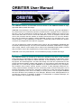
Introduction
ORBITER is a free flight simulator that goes beyond the confines of Earth’s atmosphere.
Launch the Space Shuttle from Kennedy Space Center to deploy a satellite, rendezvous with
the International Space Station or take the futuristic Delta-glider for a tour through the solar
system – the choice is yours.
But make no mistake – ORBITER is not a space shooter. The emphasis is firmly on realism
and the learning curve can be steep. Be prepared to invest some time and effort to brush up
on your maths and orbital mechanics background.
At the very least, you should familiarise yourself with the primary spacecraft controls and instrumentation in this manual to get your ship off the ground. “Advanced” missions like rendezvous manoeuvres or interplanetary trips will require a lot more effort!
Suggestions, corrections, bug reports (and praise) for the ORBITER software or this documentation are always welcome. The preferred way to post your comments, in particular if they
may be of interest to other users, is via the ORBITER mailing list or the ORBITER web forum,
available via links from the official Orbiter site:
www.medphys.ucl.ac.uk/~martins/orbit/orbit.html (alias www.orbitersim.com).
Unfortunately I can’t guarantee to answer all Orbiter-related mail sent directly to me.
Before posting a bug report make sure you have got the latest ORBITER release, and that
your problem is not already documented in the FAQ, the bug tracker or the bug forum (all accessible from the ORBITER home page).
ORBITER – the thinking being’s simulator.
Enjoy the ride!
Martin Schweiger
ORBITER User Manual (c) 2000-2005 Martin Schweiger
4
2
Installation
This section lists the computer hardware requirements for running Orbiter, and contains
download and installation instructions.
2.1
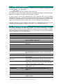
Hardware requirements
The standard ORBITER distribution requires the following minimum hardware features:
•
•
•
•
•
300MHz PC or better (Pentium, Athlon, etc.)
128MB RAM or more
Windows 95/98/Me/2000/XP
DirectX 7.0 or higher
DirectX compatible 3D graphics accelerator card with at least 16MB of video RAM (32MB
or more recommended) and DXT texture compression support
Approximately 60MB of free disk space for the minimum installation (additional highresolution textures and addons will require more space).
DirectX compatible joystick (optional)
•
•
Installing high-resolution texture packs or addons may have an impact on performance and
could require significantly higher computing specs.
Since ORBITER keeps evolving these specs tend to become obsolete over time. If you
don’t get a reasonable frame rate (say >= 20fps) using the default Orbiter.cfg on a machine
which meets the specs then please drop me a note and I will correct the requirement list
upward.
2.2
Download
The ORBITER distribution can be obtained from one of several Orbiter mirror sites on the
internet. You can find links to these mirrors at the Download page of the ORBITER site,
http://www.medphys.ucl.ac.uk/~martins/orbit/orbit.html. Orbiter is distributed in several packages (.zip files). The Base package contains the basic Orbiter system and is the only required
package. All other packages are optional extensions to the basic system.
All package names contain a 6-digit time stamp (YYMMDD) which allows to identify the modification date of the package. For example, orbiter050114_base.zip contains the base package
built on January 14, 2005. Note that not all current packages may have the same time stamp.
In particular, high-resolution planetary texture packages are rarely updated and may have an
older time stamp. Check the download pages for the latest versions of all packages.
2.3
•
•
•
•
•
•
Installation
Create a new folder for the ORBITER installation, e.g. \Program Files\Orbiter_050114.
If a previous version of ORBITER is already installed on your computer, you should not
install the new version into the same folder, because this could lead to file conflicts. You
may want to keep your old installation until you have made sure that the latest version
works without problems. Multiple ORBITER installations can exist on the same computer.
Download the Base package from an ORBITER download site into your new ORBITER
folder and unzip it with WinZip or an equivalent utility. Important: Take care to preserve
the directory structure of the package (for example, in WinZip this requires to activate the
“Use Folder Names” option).
After unzipping the package, make sure your ORBITER folder contains the executable
(Orbiter.exe) and, among other files, the Config, Meshes, Scenarios and Textures subfolders.
Run Orbiter.exe. This will bring up the ORBITER “Launchpad” dialog, where you can select video options and simulation parameters.
You are now ready to start ORBITER. Select a scenario from the Launchpad dialog, and
click the “ORBITER” button!
ORBITER User Manual (c) 2000-2005 Martin Schweiger
5
If Orbiter does not show any scenarios in the Scenario tab, or if planets appear plain white
without any textures when running the simulation, the most likely reason is that the packages were not properly unpacked. Make sure your Orbiter folder contains the subfolders as
described above. If necessary, you may have to repeat the installation process.
2.4
•
Uninstall
ORBITER does not modify the Windows registry or any system resources, so no complicated uninstallation process is required. Simply delete the Orbiter folder with all contents
and subdirectories. This will uninstall ORBITER completely.
ORBITER User Manual (c) 2000-2005 Martin Schweiger
6
3
The Launchpad
Starting Orbiter.exe brings up the Orbiter Launchpad dialog box. From here, you can
• set simulation, video and joystick parameters
• load available plugin modules to extend the basic Orbiter functionality
• select a startup scenario
• open the online help system
• launch the Orbiter simulation window, or
• exit to the desktop.
From the Launchpad dialog, the simulation can be started by pressing the “ORBITER” button,
provided a scenario has been selected. If you are running Orbiter for the first time, you should
make sure that the simulation parameters (in particular video options) are properly set before
starting the simulation.
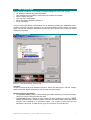
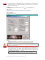
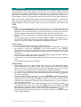
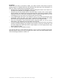
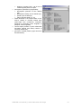
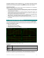
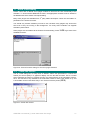
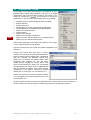
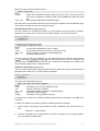
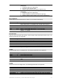
3.1
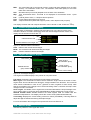
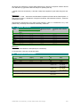
Scenario tab
Figure 1: Launchpad dialog, Scenario tab
Scenario:
Contains a hierarchical list of available scenarios. Select one and launch it with the “Orbiter”
button. Below the list is a description of the currently selected scenario.
Special scenarios and folders:
• The (Current state) scenario is automatically generated whenever you exit the simulator.
Use this to continue from the latest exit state.
• The Quicksave folder contains in-game saved scenarios generated by pressing
.
Multiple quicksaves are possible. Orbiter saves the quicksave states under the original
scenario name, followed by a quicksave counter. The counter is reset each time the
simulation is launched, so make sure to copy any scenarios you want to keep!
ORBITER User Manual (c) 2000-2005 Martin Schweiger
7
NEW!
•
The Demo folder can be filled with scenarios that are automatically run in kiosk/demo
mode (see Section 20). This allows to put together a set of simulations that can be run in
unsupervised environments.
Options:
• Start paused: Pause simulation on start. Press
to unpause after launch.
Save current:
Save the current exit state under a new name with a custom description.
Clear quicksaves:
Empty the Quicksave folder.
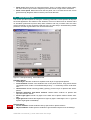
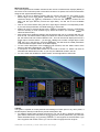
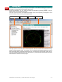
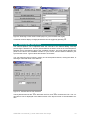
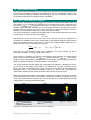
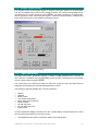
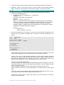
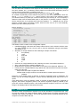
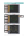
3.2
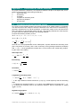
Parameters tab
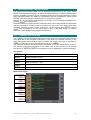
Figure 2: Launchpad dialog, Parameters tab
NEW!
Realism
• Complex flight model: Select the realism of the flight model for spacecraft.
• Limited fuel: Un-tick this box to ignore fuel consumption of your spacecraft.
Some of the more “realistic” spacecraft, such as the Space Shuttle, may NOT work properly
if “Limited fuel” is not selected, because they rely on the reduction of mass during liftoff as a
consequence of fuel consumption.
• Nonspherical gravity sources: This option activates a more complex gravity calculation
which can take into account perturbations in the gravitational potential due to nonspherical object shapes, thus allowing more accurate orbit predictions. Note that this option can
make orbital calculations more difficult, and may reduce the stability of instruments that
don’t take this effect into account. For a planet to make use of the perturbation code, its
configuration file must contain the JCoeff entry.
Technical background: Orbiter uses the following simple perturbation approach to calculate the
gravitational potential U of a celestial body as a function of its radial distance r and latitude φ:
ORBITER User Manual (c) 2000-2005 Martin Schweiger
8
U (r , φ ) =
∞
GM
R
1− J n
r
r
n =2
2
Pn (sin φ )
where M and R are the planet’s mass and equatorial radius, G is the gravitational constant, Pn is the
Legendre polynomial of order n, and Jn is the associated perturbation coefficient.
The gravitational acceleration is given by the gradient of the potential:
a = ∇U
Window focus mode
• Focus follows mouse: If this option is ticked, the input focus is switched between the
Orbiter simulation window and any open dialog boxes by moving the mouse over the window. If unticked, the focus is switched in normal Windows style by clicking the window.
NEW!
Orbit stabilisation
• Enable stabilisation: If this option is enabled, Orbiter uses an alternative method to
update the state vectors of orbiting bodies under certain conditions, where only the
perturbations of the osculating 2-body orbital elements with respect to a dominant gravity
source are dynamically propagated. This can help to avoid orbit deterioration at high time
compressions.
• G-field perturbation limit: Defines the upper limit of perturbation [%] of the gravity field
of the main gravity source under which stabilisation is enabled. A higher value will switch
to stabilisation mode even if the 2-body assumption is not very accurate. Default value is
0.01 (1%).
• Orbit step limit: This entry allows to limit the application of orbit stabilisation to time steps
which propagate an object by more than a given fraction of its full orbital path. More
precisely, orbit stabilisation will only be applied if this condition is satisfied:
v∆t > α 2πr
where v is the orbital velocity, r is the length of the radius vector, ∆t is the time step, and α
is the user-specified step limit. Default value is α = 0.0001 (0.01%).
• Note: Orbiter uses now an improved stabilisation algorithm. Unlike previous versions, this
can now account for perturbations of the gravitational field, aerodynamic and thruster
forces.
Stars
• Count: Number of displayed background stars. Orbiter uses the Hipparcos database of
more than 100000 bright stars. Specifying a large number will provide a more impressive
night sky, but may degrade performance. Set to zero to suppress background stars.
• Brightness: Brightness scaling factor for background stars. Valid range is –4 to 4 (default
1). Note that the dynamic range becomes less realistic for large values.
• Contrast: Intensity contrast used for rendering stars. Valid range is 0 to 5 (default 1).
If you use only a small part of the database, you may want to increase the contrast (e.g. to
1.5) and reduce the brightness (e.g. to 0.8). If you use the full database, values of brightness
1.5 and contrast 1.0 give good results.
Technical background: The mapping between a star’s apparent magnitude mv and pixel render
brightness c is calculated by the clamped linear relationship
c = min 1, max c 0 ,
m1 − m v
(1 − c 0 ) + c 0
m1 − m 0
c
1
where
m 0 = 2 B − 2 / C + 2,
m1 = 2 B + 2 / C + 3,
c 0 = 0.3
c0
m0
m1
mv
with B and C the user-supplied brightness and contrast values. For default values B=1, C=1, the
supported contrast range is thus m0=2 to m1=7.
Instruments
• Transparent MFD: Make the onscreen multifunctional displays transparent. This provides
a better view of the 3D environment, but makes it more difficult to read the instruments.
• MFD refresh: Time (in seconds) between MFD updates. Shorter intervals provide
smoother updates, but may degrade performance.
ORBITER User Manual (c) 2000-2005 Martin Schweiger
9
•
•
3.3
Panel scale: Sizing factor for instrument panels. Scale 1 provides optimal visual quality,
but other values may be used to adapt the panel size at low or high screen resolutions.
Panel scroll speed: Determines how fast the panel can be scrolled across the screen
[pixels/second]. Negative values invert the panel scroll direction.
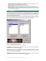
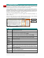
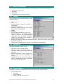
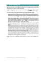
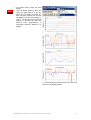
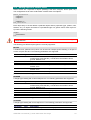
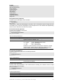
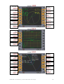
Visual effects tab
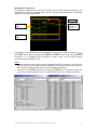
This section provides options for tuning the rendering parameters. These options will improve
the visual appearance and realism of the simulator, but most of them have an adverse effect
on simulation performance (frame rates) when enabled, and may increase video and main
memory demands, so they should be used with care. As a first step in troubleshooting Orbiter
problems, it is often a good idea to turn off all visual effects.
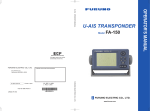
Figure 3: Launchpad dialog, Visual effects tab
Planetary effects
• Cloud layers: Render clouds as a separate mesh layer for appropriate planets.
• Cloud shadows: Render cloud shadows cast on the planet surface. Only planets whose
configuration files contain a CloudShadowDepth entry < 1 will actually render cloud shadows.
• Horizon haze: Render intensity-graded (“glowing”) horizon layer for planets with atmospheres.
• Specular reflections from water surfaces: Render water surfaces on planets with
specular reflection effects.
• Planet night lights: Render city lights on the dark side of planet surfaces where available.
• Night light level: Defines the brightness of night city lights. Valid range is 0 to 1. (ignored
if planet night lights are disabled)
NEW!
General effects
• Vessel shadows: Enable shadows cast by spacecraft on planet surfaces.
• Object shadows: Enable dynamic shadows of ground-based objects such as buildings.
ORBITER User Manual (c) 2000-2005 Martin Schweiger
10
•
•
•
•
3.4
Specular reflections from objects: Render reflective surfaces like solar panels, window
panes or metallic surfaces. May degrade performance.
Reentry flames: Render glowing plasma hull during reentry.
Particle streams: Render ionised exhaust gases and vapour trails with particle effects.
Ambient light level: Defines the brightness of the unlit side of planets and moons. Ambient level 0 is the most realistic, but makes it difficult to spot objects in the dark. Level 255
is uniform lighting (no darkness).
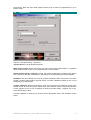
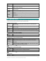
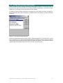
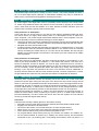
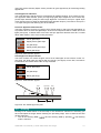
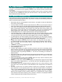
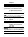
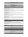
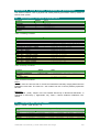
Modules tab
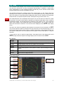
This tab allows to activate and deactivate plugin modules for Orbiter which can extend the
functionality of the core simulator. Plugins can contain additional instruments, dialogs, interfaces to external programs, etc. Make sure you only activate modules you actually want to
use, because modules can take up some processing time even if they run in the background,
and thus affect Orbiter's performance.
The modules provided with the standard Orbiter distribution are demos from the SDK packrd
age, and are available in full source code. A wide variety of additional modules by 3 party
add-on developers can be downloaded from Orbiter repositories on the internet.
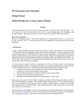
Figure 4: Launchpad dialog, Modules tab
Some of the standard modules distributed with Orbiter are:
CustomMFD: This module provides an additional “Ascent MFD” mode for the multifunctional
displays, which can be selected via
.
Rcontrol: Remote control of ship engines. This allows to manipulate vessels even if they
don’t have input focus. If this module is active, the remote control window can be selected
from the Custom Functions list (
).
FlightData: Real-time atmospheric flight data telemetry. If this module is active, the flight data
window can be selected from the Custom Functions list (
).
ORBITER User Manual (c) 2000-2005 Martin Schweiger
11
Framerate: A graphical simulation frame rate (FPS) display. If this module is active, the frame
rate window can be selected from the Custom Functions list (
).
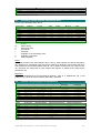
3.5
Video tab
Figure 5: Launchpad dialog, Video tab
3D Device: Lists the available hardware and software devices for 3D rendering. Select a
hardware device when possible, such as Direct3D HAL or Direct3D T&L HAL. Software devices such as RGB Emulation will produce poor performance. Note that some hardware devices do not support window mode.
Always enumerate devices: Tick this box if Orbiter does not display 3D devices or screen
modes correctly. This option enforces a hardware scan whenever Orbiter is launched and
skips the device data stored in device.dat. Make sure to tick this box after upgrading your
graphics hardware or DirectX/video drivers to make Orbiter aware of the changes.
NEW!
Try stencil buffer: Enables stencil buffering, if the video mode supports it. Stencil buffers can
improve various visual effects (for example, provide support for alpha-blended shadows), but
have a slight impact on frame rates. If the selected video mode doesn’t support stencil
buffers, this option is ignored.
Full Screen: Select this option to run Orbiter in fullscreen mode. You can choose the screen
resolution and colour depth from the lists provided. Only modes supported by the selected
device are listed here. Higher resolution and colour depth will improve the visual appearance
at the cost of reduced performance.
In addition, you can select the Disable vertical sync option. This allows Orbiter to update a
frame without waiting for a synchronisation signal from the monitor. This can improve frame
rates, but may lead to visual artefacts (tearing).
Window: Select this option to run Orbiter in a window. You can specify the size of the render
window here. For best results, use a width:height ratio close to 4:3 (or tick the Force 4:3 aspect ratio button to keep the optimal aspect ratio). Large window sizes can reduce simulation
ORBITER User Manual (c) 2000-2005 Martin Schweiger
12
performance. Note that some older graphics drivers may not allow 3-D applications to run in
window mode.
3.6
Joystick tab
Figure 6: Launchpad dialog, Joystick tab
Joystick device: Lists all attached joysticks.
Main engine control: Define the joystick axis which controls the main thrusters. Try different
options if the throttle control on your joystick doesn’t work in Orbiter.
Ignore throttle setting on launch: If ticked, the joystick throttle will be ignored at the launch
of a scenario util the user manipulates it. Otherwise, the throttle setting is used immediately.
Deadzone: Use this to define how soon the joystick will respond when moved out of its centre
position. Smaller values make it respond sooner. Increase if attitude thrusters do not cut out
completely in neutral position.
Throttle saturation: Defines the tolerance zone at the minimum and maximum range of the
throttle control at which the joystick reports zero and maximum throttle, respectively. Reduce
if main engines do not cut out completely at minimum throttle setting. (Applies only to joysticks with throttle control).
If further calibration is required you should use the appropriate tools in the Windows Control
Panel.
ORBITER User Manual (c) 2000-2005 Martin Schweiger
13
4
Quickstart
This section demonstrates how to take off and land with one of Orbiter’s default spacecraft,
the Delta-glider. If you are using Orbiter for the first time, this will help to familiarise yourself
with some basic concepts of spacecraft and camera control. You should also read the rest of
this manual, in particular sections 5 and 7 on keyboard and joystick interface, section 13 on
instrumentation, section 14 on spacecraft controls, and section 16 on basic flight manoeuvres.
Make sure you have configured Orbiter before launching your first simulation, in particular the
video and joystick parameters (see section 3). Once you have started the scenario, you can
get the following scenario instructions also on-screen by opening the Help window with
.
Starting:
• Select the Checklists|Quickstart scenario (see Section 3.1 on scenario selection), and
press the “Launch ORBITER” button to launch the scenario. Once the mission has been
loaded (this can take a few moments), you will see in front of you runway 33 of the SLF
(Shuttle Landing Facility) at the Kennedy Space Center, Cape Canaveral, Florida.
• You are in control of a Delta-glider, a powerful futuristic spacecraft, aligned and ready for
takeoff.
• You can always exit the simulation by pressing
or
, or by clicking “Exit” on
the main menu ( ). Orbiter saves the current simulation status in the “(Current status)”
scenario, so you can continue your flight later by selecting this scenario.
Camera modes:
You are in an external camera mode, looking towards your ship.
• You can rotate the camera around your ship by pressing and holding down the
key
and pressing a cursor key (
) on the cursor keypad of your keyboard.
Alternatively you can press the right button on your mouse and drag the mouse to rotate
the camera. Or, if you have a joystick with a direction controller (“coolie hat”), you can use
that as well.
• To jump into the cockpit of your glider, press
.(
always toggles between cockpit and
external view of the spacecraft you are controlling).
• In the cockpit, you can look around by rotating the camera in the same way as in external
views.
• To look straight ahead, press the
button.
Cockpit modes:
• At the moment, you are in "virtual cockpit" mode - that is, you are inside a three-dimensional representation of the glider cockpit, with the glass pane of the head-up display
(HUD) in front of you, and the instruments and controls arranged around you. If you look
back, you can even get a glimpse of your passengers in the cabin behind you!
• You can switch to a different cockpit mode by pressing
. Pressing
once will open
the "generic" cockpit mode with only the HUD and two instruments. Pressing
again will
open a 2-D panel mode.
• The panel can be scrolled by pressing a cursor key (
) on the cursor keypad. To
scroll the panel out of the way, press
. You should now be able to see the runway
stretching in front of you. Scrolling the panel is useful if you want to see more of your surroundings. Also, if the panel is larger than your simulation window, you can scoll different
parts of the panel into view.
• Some spacecraft have more than a single panel which can be accessed by pressing
in combination with a cursor key. If you press
, you will see the glider’s overhead
panel with some additional controls. Pressing
twice will bring up the lower panel
with brake and gear controls. For now, switch back to the main panel with
.
• Not all spacecraft types support 2-D panels or 3-D virtual cockpits, but the generic cockpit
mode is always available.
ORBITER User Manual (c) 2000-2005 Martin Schweiger
14
MFD instruments:
The most important and versatile instruments are the two multifunctional displays (MFDs) in
the centre of the instrument panel. Each MFD consists of a square CRT screen and buttons
along the left, right and bottom edges.
• MFDs can be set to different modes: With the mouse, left-click the “Sel” button at the
bottom edge of one of the MFDs. (Alternatively, you can press
. MFD keyboard
interfaces always use
key combinations, where the left
key controls the left
MFD, and the right
key controls the right MFD). You will see a list of available
modes.
• Click on one of the buttons along the left or right edge to select the corresponding mode.
If you click the top-left button, the MFD switches to Orbit mode.
• Modes can also be selected directly with a
key combination. The key combinations
used for selecting a mode a listed in grey below the modes. (For example,
will
select the Orbit mode.)
• Most modes have additional settings and parameters that can be controlled with the buttons as well. The button labels change to indicate the various mode functions. For example, the Orbit mode has a button labelled “TGT”. This can be used to display the orbit of a
target object. Click this button – you will see a dialog box to select a target object. Press
, type “iss” in the text box, and press
again. This will show the orbital parameters
of the International Space Station in the MFD display.
• To see a short description of the available mode functions, click the “MNU” button at the
bottom of the MFD (Alternatively, use
).
• A description of standard MFD modes can be found in Section 13. Orbiter can also be
extended with addon MFD modes, so you may see additional modes in the list.
• For now, switch the left MFD to Surface mode, and the right MFD to HSI mode.
Takeoff:
Your glider is capable of runway takeoffs and landings on Earth (and on any other planet, if
the atmospheric density is sufficient to provide aerodynamic lift).
• For takeoff, engage main engines at full thrust. You can do this by pushing the Main engine sliders at the left of the panel to the top using the mouse (make sure you push both
sliders simultaneously!), or by pressing
Numpad until engines are at full throttle. If you
have a joystick with throttle control, you can use that to engage the main engines.
ORBITER User Manual (c) 2000-2005 Martin Schweiger
15
•
•
•
Your spacecraft will start to roll. You can check the speed (in meters/second) on the
AIRSPD indicator of the Surface MFD, or on the HUD (head-up display) – the value in the
green box at the top right of the screen.
When the airspeed reaches 100 m/s, pull back on the joystick to rotate, or press and hold
Numpad.
Once clear of the runway, press
to raise the landing gear.
When the atmosphere is too thin to produce enough lift for a runway takeoff (for example
when taking off from the Moon) or when no runway is available, you can use the glider’s
hover engines to lift off:
• Move the Hover slider on the instrument panel up by clicking and dragging with the
mouse. Alternatively, press the
Numpad key until hover engines are fully engaged.
• Your glider should now lift off vertically. Once clear of the ground, engage main engines.
Note that a fully loaded and tanked glider may be too heavy to lift off vertically from Earth
when the “realistic” flight model is used.
• As you gain airspeed, you can gradually reduce hover thrust.
Atmospheric flight:
In the lower atmosphere, the glider behaves very much like an aircraft. Try the joystick controls for pitch, roll and yaw to get a feeling for handling at different altitudes. Without a joy/ Numpad for roll, and
stick, you can use the numerical keypad ( / Numpad for pitch,
/ Numpad for yaw). The glider has powerful rocket engines, but their performance depends
on atmospheric pressure (at very low altitudes, it will not even go supersonic).
This is a good time to try different camera modes. Open the Camera dialog (
), and
check the effect of different track modes and field of view (FOV) settings.
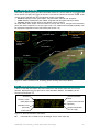
Landing:
• Go around and approach runway 33 of the SLF from the south. Line up with the runway.
Your HSI instrument helps to maintain the correct approach path and slope. One of its
two displays should already be tuned to the runway ILS system. The HSI contains a
course pointer, deviation and glideslope indicator. It works like a standard aircraft instrument, so you may already be familiar with its use. If not, check section 13.4 for details.
• As you approach the runway, you will see PAPI and VASI landing aids in front of and beside the runway (see section 16.6). The PAPI is of limited use here, because it is adjusted
for the Space Shuttle’s steep descent slope of 20°.
• Throttle back and engage airbrakes (
) to reduce speed. Lower the landing gear
( ).
ORBITER User Manual (c) 2000-2005 Martin Schweiger
16
•
After touchdown, engage left and right wheel brakes (
stop.
and
) until you come to a full
Space flight:
So far we have treated the glider much like a conventional aircraft. Now it is time to aim a bit
higher ...
• Take off as before. Turn east (use the compass ribbon at the top edge of the HUD, or the
one in the Surface MFD display), and pitch up to 50°.
• As you gain altitude, you will notice that your craft starts to behave differently, due to the
reduction in atmospheric pressure. One of the effects is a loss of lift, which causes the
flight path indicator (the ⊕ HUD marker) slowly to drift down. Another effect is the loss of
response from your aerodynamic control surfaces.
• At about 30km altitude your glider will start to drop its nose even while you are pulling
back on the stick. Now activate the RCS (Reaction Control System) by right-clicking the
“RCS Mode” selector (on the right side of the instrument panel) or by pressing
Numpad. You are now controlling your craft with attitude thrusters.
• Pitch down to about 20°. After leaving the dense part of the atmosphere, you need to gain
tangential velocity to achieve orbit. Your flight path indicator should stay above 0°.
• Now is a good time to activate the Orbit mode in one of your MFDs. This shows the shape
of your current orbit (the green curve) in relation to the planet surface (the grey circle),
together with a list of orbital parameters along the left side of the display. You should
switch the display to “current orbital plane” projection mode, by clicking on the “PRJ”
button until “Prj: SHP” is shown in the top right corner of the display.
• At the moment, your orbit will be a rather eccentric ellipse, which for the most part is below Earth’s surface. This means that you are still on a ballistic trajectory rather than in a
stable orbit. As you keep gaining tangential velocity, the orbit will start to expand. Once
the green curve is completely above the planet surface (and sufficiently high above the
atmosphere) you will have entered orbit.
• At this point, the most important pieces of information from the Orbit display are the orbital
velocity (“Vel”) and apoapsis distance (“ApD”). For a low Earth orbit, you need to achieve
a velocity of at least 7800 m/s. Once you reach this value, you will see the orbit rising
rapidly above Earth’s surface. At the same time, the apoapsis distance (the highest point
of the orbit) will start to grow. Keep firing your engines until ApD reaches about 6.670M.
This corresponds to an altitude of 300km. Now cut the engines.
• You are now nearly in orbit. All that remains to do is raise the periapsis (the lowest point
of the orbit) to a stable altitude. This is done best when you reach apoapsis, which should
be half an orbit (or about 45 minutes) from your current position. Time to switch into an
external camera mode and enjoy the view!
• It is also a good idea to switch the HUD from surface to orbit mode now. Do this by clicking the “OBT” button in the top left corner of the instrument panel, or by pressing
twice. In this mode, the HUD flight path ladder is aligned with the orbital plane instead of
the horizon plane, and there is a ribbon showing your orbital azimuth angle. It also shows
indicators for prograde (the direction of your orbital velocity vector) and retrograde (the
opposite direction).
• When you approach apoapsis, turn your craft prograde. You can see how close you are
to the apoapsis point by checking the ApT (time to apoapsis) value in the Orbit MFD. If it
takes too long, press
to engage time acceleration, and ! to switch back. To turn
prograde, you can activate the RCS manually, but it is easier to leave it to the automatic
attitude control, by simply pressing the “Prograde” button on the right of the instrument
panel (or ").
• Now fire your main engines for final orbit insertion. The two parameters to watch are the
orbit eccentricity (“Ecc”) and periapsis distance (“PeD”). The eccentricity value should get
smaller, indicating that the orbit becomes more circular, while the periapsis distance approaches the apoapsis distance (ApD). Once the eccentricity value reaches a minimum,
turn the main engines off. You can also deactivate the prograde attitude mode by clicking
“Prograde” again.
• Congratulations! You made it into orbit!
ORBITER User Manual (c) 2000-2005 Martin Schweiger
17
Deorbiting:
Should you ever want to come back to Earth, you need to deorbit. This means to drop the
periapsis point to an altitude where the orbit intersects the dense part of the atmosphere, so
that your vessel is slowed down by atmospheric friction.
• Deorbit burns are performed retrograde. Click the “Retrograde” button, wait until the vessel attitude has stabilised, and engage main engines.
• Keep burning until the periapsis point is well below Earth’s surface, then cut the engines.
Strictly speaking, the deorbit burn must be timed precisely, because too shallow a reentry
angle will cause you to skid off the atmosphere, while too steep an angle will turn you into
a shooting star. For now we are not concerned with such fine detail...
• Turn prograde again and wait for your altitude to drop. As you enter the lower part of the
atmosphere, friction will cause your velocity to decrease rapidly. Reentries are usually
performed with a high angle of attack (AOA) – about 40° for the Space Shuttle.
• Once your aerodynamic control surfaces become responsive again you can turn off the
RCS system. Your glider has now turned back into an aircraft.
• You have probably ended up a long way from your launch point at the KSC. Re-entering
towards a specified landing point requires some practice in timing the deorbit burn and
the reentry flight path. We’ll leave this for a later mission. For now, simply look for a dry
patch to land your glider.
• This completes your first orbital excursion!
You are now ready to try more advanced missions. Try the “Launch to docking with the ISS”
flight described in section 18. First you might want to learn a bit more about orbital manoeuvres and docking procedures in section 16.
ORBITER User Manual (c) 2000-2005 Martin Schweiger
18
5
NEW!
Getting help
From the Orbiter launchpad, you can get a description of the different dialog box options by
pressing the “Help” button in the bottom right corner.
During the simulation you can open the Orbiter help window by pressing
, or by selecting “Help” from the main menu ( ).
The help system provides information about MFD modes, and optionally a description of the
current scenario or the currently active spacecraft.
Table of contents
Scenario info
Vessel info
Help page
The help system is currently still under development. Not all scenarios and vessels currently
support context-sensitive help. The system can be extended by adding additional scenario
and vessel help pages, and addon developers are encouraged to use the help system to provide user-friendly information about their spacecraft, or provide documented tutorial scenarios
that illustrate the features of their plugins.
ORBITER User Manual (c) 2000-2005 Martin Schweiger
19
6
NEW!
Keyboard interface
This section describes the default Orbiter keyboard functions. Please note that the key
assignments are customizable by editing the keymap.dat file in the orbiter directory, and that
therefore the keyboard controls for your Orbiter installation may be different.
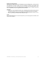
The key assignment reference in this section and the rest of the manual refers to the keyboard layout shown in Figure 7. For other layouts (e.g. language-specific) the key labels may
be different. The relevant criterion for key functions in Orbiter is the position of the key on the
keyboard, not the key label. For example, on the German keyboard, the keys for the “turn orbit-normal” (;) and “turn orbit-antinormal” (’) will be “Ö” and “Ä”.
Keys from the numerical keypad or the cursor keypad will be denoted by subscript, e.g.
Numpad or
Cursorpad.
Note that certain spacecraft may define additional keyboard functions. Check individual
manuals for a detailed description of spacecraft controls and functionality.
Cursor pad
Numpad
Figure 7: Keyboard layout reference
6.1
General
#
$
%
Toggle frame rate info on/off
Toggle display of information about current object and camera mode.
Time warp shortcut: Slow down simulation by factor 10 (down to realtime). See also Time acceleration dialog (
&)
Time warp shortcut: Speed up simulation by factor 10 (up to a maximum
warp factor of 10000). See also Time acceleration dialog (
&)
Zoom out (increase field of view). See also Camera dialog (
)
'
(
)
Zoom in (decrease field of view). See also Camera dialog (
*
)
Undock from a vessel.
Pause/resume simulation.
+
,
Exit to Launchpad dialog.
Quicksave scenario.
Toggle internal/external view of the user-controlled spacecraft.
Open the Camera dialog to select camera target, view mode and field of
view.
&
&
-
Toggle tracking mode for external camera views (target-relative / absolute
direction / global frame).
Open the Time acceleration dialog. This allows to speed up/slow down the
simulation, and to pause/resume.
Open vessel dialog to switch control to a different spacecraft.
-
Switch control back to the previously active vessel. This allows to quickly
ORBITER User Manual (c) 2000-2005 Martin Schweiger
20
switch backwards and forwards between two vessels.
Main menu.
Open the Custom functions dialog. Contains a list of functions defined in
plugin modules, if available.
.
Open the Object Info dialog for object-specific data such as ILS navaid
frequencies etc.
/
0
Open the Map dialog (spaceports, navaid locations etc.)
1
Open the Planetarium options dialog for controlling the display of grids
and markers.
Open the Navaid Info dialog containing a list of navigational radio
beacons.
1
6.2
“Planetarium mode”: Toggle display of constellations.
Spacecraft controls
These keys allow manual maneuvering of the user-controlled spacecraft. See also joystick
controls. Note some spacecraft may not define all thruster types.
Main/retro thruster controls:
Numpad
2Numpad
3Numpad
Numpad
2Numpad
Accelerate by increasing main thruster setting or by decreasing retro
thruster setting.
Decelerate by decreasing main thruster setting or by increasing retro
thruster setting.
Kill main and retro thrusters.
Fire main thrusters at 100% while pressed (overrides permanent setting)
Fire retro thrusters at 100% while pressed (overrides permanent setting)
Hover thruster controls (where available):
Numpad
Numpad
Increase hover thruster setting.
Decrease hover thruster setting.
Attitude thruster controls (rotational mode):
/
/
/
Numpad
Numpad
Numpad
4Numpad
Engage attitude thrusters for rotation around longitudinal axis (bank)
Engage attitude thrusters for rotation around transversal axis (pitch)
Rotational mode: Engage attitude thrusters for rotation around vertical
axis (yaw)
Toggle “Kill rotation” navigation computer mode. Stops spacecraft rotation
by engaging appropriate attitude thrusters
Note: In combination with
, thrusters are engaged at 10% max. thrust for fine control.
Attitude thruster controls (linear mode):
/
/
/
Numpad
Numpad
5Numpad
Engage attitude thrusters for up/down translation.
Engage attitude thrusters for left/right translation.
Engage attitude thrusters for forward/back translation
Note: In combination with
, thrusters are engaged at 10% max. thrust for fine control.
Other controls:
Numpad
Toggle reaction control thruster mode between rotational (engage
ORBITER User Manual (c) 2000-2005 Martin Schweiger
21
opposite thruster pairs) and linear (engage parallel thruster pairs)
Numpad
Numpad
Enable/disable reaction control system (RCS). The RCS (if available) is a
set of small thrusters which allows attitude (rotation) and linear control of
the spacecraft.
Enable/disable manual user control (via keyboard or joystick) of
aerodynamic control surfaces (elevator, rudder, ailerons) if available.
6
Toggle “Hold altitude” navcomp mode. Maintain current altitude above
surface by means of hover thrusters only. This will fail if hover thrusters
cannot compensate for gravitation, in particular at high bank angles.
Combining this mode with the “H-level” mode is therefore useful.
7
Toggle “H-level” navcomp mode. This mode keeps the spacecraft level
with the horizon by engaging appropriate attitude thrusters.
"
Toggle “Turn prograde” navcomp mode. This mode turns the spacecraft
into its orbital velocity vector.
8
Toggle “Turn retrograde” navcomp mode. This mode turns the spacecraft
into its negative orbital velocity vector.
9
Toggle “Turn orbit-normal” navcomp mode. Rotates spacecraft normal to
its orbital plane (in the direction of R × V )
:
Toggle “Turn orbit-antinormal” navcomp mode. Rotates spacecraft
antinormal to its orbital plane (in the direction of − R × V )
;/<Cursorpad
Trim control (only vessels with aerodynamic surfaces)
Apply left wheel brake (where applicable)
Apply right wheel brake (where applicable)
6.3
=
>
External camera views
Move camera away from target object.
Move camera towards target object.
Rotate camera around object.
In ground-based camera views,
will change the observer altitude, and
locked to the target).
6.4
will move the observer position, = and >
will rotate the observer direction (unless
Internal (cockpit) view
The two multifunctional displays (MFD) on the left and right side of the screen are controlled
via left/right Shift key combinations, where the left Shift key addresses the left MFD, the right
shift key addresses the right MFD.
The Head-up display (HUD) and MFDs are visible only in internal cockpit view.
Toggle between generic, 2D panel, and 3D virtual cockpit modes (if
supported by the current spacecraft)
Rotate view direction.
Return to default view direction.
Scroll instrument panel (in 2D panel view).
Switch to neighbour panel, if available (in 2D panel view).
ORBITER User Manual (c) 2000-2005 Martin Schweiger
22
Toggle HUD display on/off.
Switch HUD mode.
%
HUD reference selection.
Orbit HUD: opens reference selection input box.
Docking HUD: steps through available NAV receivers.
%
Docking HUD: Reference selection, bypassing XPDR and IDS
transmitters.
Open a menu for left/right MFD mode selection.
Open/page/close the MFD-specific parameter selection menu.
6
*
7
/
?
,
(
@
+
Display Align orbital plane mode MFD.
Display Docking mode MFD.
Display Launch/landing mode MFD.
Display Map mode MFD.
Display Orbit mode MFD.
Display Surface mode MFD.
Display Transfer mode MFD.
Display Synchronise orbit mode MFD.
Turn off MFD.
Docking Mode MFD
'
Input new docking target.
Align orbital plane Mode MFD
'
Input new target object.
Orbit Mode MFD
6
A
/
0
Auto-select reference object.
Toggle frame reference (ecliptic, or equator of reference object).
Toggle display mode (list only, graphics only and both)
No target orbit.
Toggle orbit projection mode (ecliptic, ship’s and target’s orbital plane)
%
'
Select new reference object (planet or moon) for orbit calculation.
Open menu for target selection.
Map Mode MFD
%
'
B
)
"
8
2
Open input box for reference planet/moon selection.
Open a menu for target selection.
Switch automatic vessel track mode on or off.
Toggle between global map view and 2x zoom.
Scroll map display left (not in track mode)
Scroll map display right (not in track mode)
Scroll map display up (not in track mode or global view)
ORBITER User Manual (c) 2000-2005 Martin Schweiger
23
C
Scroll map display down (not in track mode or global view)
Transfer Mode MFD
%
Open input box for reference planet/moon selection.
Open a menu for source orbit object selection.
'
0
(
/
D
E
Open a menu for target selection.
Unselect target.
Toggle (hypothetical) transfer orbit display on/off.
Toggle numerical multibody trajectory calculation.
Refresh numerical trajectory, if displayed.
Open input box for time step definition.
/
2 /C
Rotate transfer orbit ejection longitude.
Decrease/increase transfer orbit major axis.
Synchronise orbit Mode MFD
'
/
0
Input new target object (vessel or moon)
Change reference axis.
Select number of entries in the reference transit time list.
/
6.5
Rotate reference axis (in manual mode only).
Menu selections
Move to previous item in the list.
Move to next item in the list.
Display sub-list for selected item, if available.
Go back to the parent list from a sub-list.
Select current item and close list.
F
Cancel list.
ORBITER User Manual (c) 2000-2005 Martin Schweiger
24
7
Joystick interface
A joystick can be used to operate the attitude and main thrusters of the user-controlled
spacecraft manually.
Action
Push stick left or right
Push stick forward or
backward
Operate rudder control
or
Push stick left or right while
holding joystick button 2
Operate throttle control
Direction controller (“coolie
hat”)
Direction contoller + joystick
button 2
Effect
Rotate around vessel’s longitudinal axis (bank)
Rotate around vessel’s transversal axis (pitch)
Rotate around vessel’s vertical axis (yaw)
Controls main thruster settings. This is similar to the
Numpad and
2 Numpad keyboard controls, but it
affects only the main thrusters, not the retro thrusters.
Cockpit view: rotate view direction
External view: rotate camera around the observed object
Cockpit view: scroll instrument panel (if applicable)
External view: rotate view direction (ground observer mode
only)
ORBITER User Manual (c) 2000-2005 Martin Schweiger
25
8
Mouse interface
Spacecraft instrument panels can be operated by the mouse. Most buttons, switches and dials are activated by pressing the left mouse button. Some elements like multi-way dials may
respond to both left and right mouse buttons.
In external camera modes, the mouse wheel control (if available) can be used to move the
camera towards or away from the view target. The mouse wheel acts like the = and > keys.
The camera direction can be rotated by holding down the right mouse button and dragging
the mouse. This works both in external and cockpit views.
The mouse can of course also be used to select and manipulate dialog controls.
ORBITER User Manual (c) 2000-2005 Martin Schweiger
26
9
Spacecraft classes
The following standard spacecraft types are currently available in the Orbiter standard distribution. Many more can be downloaded as add-ons. See the Orbiter web site for a list of addon repositories.
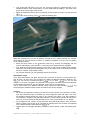
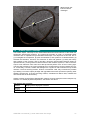
9.1
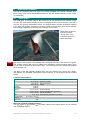
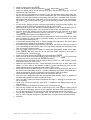
Delta-glider
The Delta-glider is the ideal ship for the novice pilot to get spaceborne. Its futuristic design
concept, high thrust and extremely low fuel consumption make it easy to achieve orbit, and it
can even be used for interplanetary travel. The winged design provides aircraft-like handling
in the lower atmosphere, while the vertically mounted hover-thrusters allow vertical takeoffs
and landings independent of atmospheric conditions and runways.
Delta-glider model and
textures by Roger
“Frying Tiger” Long.
Instrument panels by
Martin Schweiger.
NEW!
Two versions are available: The standard DG is equipped with main, retro and hover engines.
The scramjet version (DG-S) has in addition two airbreathing scramjet engines fitted, which
can be used for supersonic atmospheric flight. The scramjets have an operational airspeed
range of Mach 3-8.
The glider comes with operating landing gear, nose cone docking port, airlock door, deployable radiator and animated aerodynamic control surfaces. It now supports particle exhaust
effects.
Technical specifications:
3
Mass
12.0·10 kg
3
11.4·10 kg
3
0.6·10 kg
3
24.0·10 kg
Length
17.76 m
Wingspan
17.86 m
5
Thrust
2 x 1.2·10 N
4
2 x 2.7·10 N
4
3 x 9.0·10 N
4
Isp
4·10 m/s
2
Inertia (PMI)
15.5 / 22.1 / 7.7 m
Stall CL
1.0
Stall AOA
20°
(empty orbiter)
(main fuel load)
(RCS fuel load)
(total)
(main engines)
(wing-mounted retro thrusters)
(hover thrusters)
(fuel-specific impulse in vacuum)
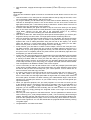
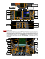
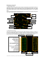
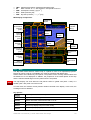
Main and overhead instrument panels:
Turn the panels on and off with
. The glider supports three panels which can be selected
with
and
.
ORBITER User Manual (c) 2000-2005 Martin Schweiger
27
left/right scramjet
temperature: diffusor,
combustion, exhaust
Torque angular
acceleration/angular
velocity indicators
Nosecone/airlock
operation
left MFD
right MFD
AF/RCS
selectors
HUD mode
selector
navmodes
main throttle, gimbal
control
pitch trim
control
hover throttle, balance
control
main/RCS
fuel status
scram fuel
status
scram throttle, gimbal
control
main engine
status
scram engine
status
artificial
horizon
slope/range
indicator
AOA
indicator
slip
indicator
landing gear
control/status
left/right
wheel brake
nose cone
control/status
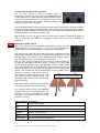
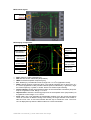
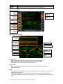
NEW!
Virtual cockpit
The delta-glider supports a 3-D virtual cockpit (VC) mode in addition to the 2-D panel mode.
Switch between cockpit modes by pressing
. The VC puts you in the pilot’s seat, with the
head-up display in front of you, and all controls and displays within easy reach. You can operate switches and levers with the mouse. Look around you by pressing the right mouse button and dragging the mouse, by using
, or with the coolie hat on your joystick.
You can also lean left, right and forward with
, to get a better view of your
surroundings.
navmode
panel
HUD
HUD mode
panel
left MFD
hover f/b
balance
indicator
lights
airfoil
control
right MFD
HUD color/
brightness
scramjet
gimbal
airlock
control
RCS
control
nosecone
main
gimbal
trim
angular
vel./mom.
scramjet
temperature
fuel level
fuel status
horizon
slope
AOA/
slip
ORBITER User Manual (c) 2000-2005 Martin Schweiger
controls
gear
28
RCS and aerodynamic control selection
The AF CTRL selector is used to activate control of
aerodynamic surfaces via manual user input. Manipulating the
control surfaces is only effective within an atmosphere at sufficiently high dynamic pressures. The settings are: OFF (control
surfaces disconnected), ON (control surfaces enabled), and
PITCH (only pitch control enabled).
The RCS MODE selector sets the Reaction Control System mode which is used to control attitude in free space. During atmospheric flight, when aerodynamic control surfaces are active,
the RCS is usually disabled. The selector can be set to OFF (RCS disabled), ROT (RCS in
rotational mode), and LIN (RCS in linear mode).
Both selectors can be set with the left and right mouse buttons. Shortcuts for RCS are
Numpad (ROT/LIN) and
Numpad (ON/OFF). Shortcut for AF control is
Numpad
(ON/OFF).
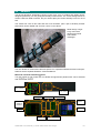
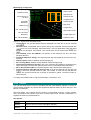
NEW!
Main engine gimbal control
Both main engines can be gimballed independently in pitch and yaw.
Gimbal range is ±1.0° in pitch, and ±7.7° in yaw. The yaw range allows to
compensate for torque generated by a single engine at main thrust.
The main engine pitch and yaw gimbal controls are arranged left of the
main throttle. The gimbal setting is controlled by flip switches for the left
and right engine. The gimbals can be operated for both engines individually, or simultaneously by clicking between the switches.
Both the pitch and jaw gimbals can be returned to neutral position by
pressing the appropriate “CENTER” button. In addition, the yaw gimbal
control supports divergent (“DIV”) and automatic (“AUTO”) settings: With
“DIV”, both engines are set to divergent thrust at their extreme limit, so
that both thrust vectors are aligned with the glider’s centre of gravity; with
“AUTO”, both engines are set to parallel thrust, and the gimbal angle is
adjusted so that the total thrust vector is
aligned with the centre of gravity, even if the
Yaw gimbal DIV and AUTO modes
two engines produce different thrust. The
automatic mode remains active until another
mode is selected.
The current setting of pitch and yaw gimbals
is shown by indicators next to the controls.
The scramjet version (DG-S) has additional
gimbal controls for the scramjet engines. The
scramjets can only be gimballed in a single
axis (pitch). The controls are identical to the
main pitch controls.
Vessel-specific key controls:
G
H
?
Operate landing gear
Operate nose cone docking mechanism
Open/close outer airlock door
Deploy/retract airbrakes
*
Deploy/retract radiators
+Space
Open animation control dialog box
ORBITER User Manual (c) 2000-2005 Martin Schweiger
29
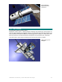
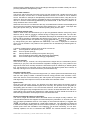
9.2
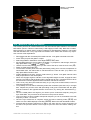
Shuttle-A
The all-new Shuttle-A, designed by Roger “Frying Tiger” Long. A medium size freight-vessel,
designed preliminary for low gravity/low density environments. The current design allows to
achieve LEO from Earth’s surface, but you need to plan your ascent carefully not to run out of
fuel.
The vessel has a set of two main and two hover thrusters, plus a pair of auxiliary thruster
pods which can be rotated 180° for main, hover or retro thrust.
Model design: Roger
Long. Instrument
panels and module
code: Martin
Schweiger.
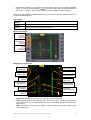
The new Shuttle-A comes with instrument panels. For operational details and technical specifications see the separate Shuttle-A Technical Manual.
Main and overhead instrument panels:
Turn the panels on and off with
. The Shuttle-A supports two panels which can be selected
with
and
.
Fuel tank/pump
status indicator
Airlock/lock
cover control
main engines
hover engines
thrust indicators
RCS mode
selector
Navmode
selectors/
indicators
right MFD
left MFD
aux engines
aux pod tilt controls
ORBITER User Manual (c) 2000-2005 Martin Schweiger
30
Vessel-specific key controls:
H
?
9.3
Operate docking hatch mechanism
Open/close outer airlock door
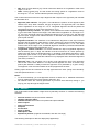
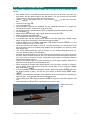
Shuttle PB (PTV)
The PB is a very agile single-seater. It produces little lift in atmospheric flight, and depends on
its hover thrusters for takeoff and landing. Aerodynamic control surfaces are not supported in
this version. Attitude control is performed via the RCS (reaction control system).
Overall design and
textures: Balázs Patyi.
Model improvements:
Martin Schweiger
Technical specifications:
Mass
Length
Thrust
Isp
9.4
500 kg
750 kg
1250 kg
7m
4
3.0·10 N
4
2 x 0.75·10 N
4
5.0·10 m/s
(empty orbiter)
(fuel capacity)
(total)
(main)
(hover)
(fuel-specific impulse in vacuum)
Dragonfly
The Dragonfly is a space tug designed for moving payload in orbit. It may be used to bring
satellites delivered by the Space Shuttle into higher orbits, or to help in the assembly of large
orbital structures.
The Dragonfly has no dedicated main thrusters, but a versatile and adjustable reaction control
system.
THE DRAGONFLY IS NOT DESIGNED FOR ATMOSPHERIC DESCENT OR SURFACE
LANDING!
ORBITER User Manual (c) 2000-2005 Martin Schweiger
31
Dragonfly original
design: Martin
Schweiger. Model
improvements and
textures: Roger Long.
Systems simulation
and instrument panels:
Radu Poenaru.
The Dragonfly is the first vessel to be modelled with detailed electrical and environmental
systems simulation, contributed by Radu Poenaru. For detailed information see the Dragonfly
Operations Handbook.
Technical specifications:
3
Mass
7.0·10 kg
3
11.0·10 kg
Length
14.8 m
Width
7.2 m
Height
5.6 m
(empty)
(100% fuel)
Propulsion system
RCS mounted in 3 pods (left, right, aft) total 16 thrusters
Thrust rating
1.0 kN per thruster
4
Isp
4.0·10 m/s (vacuum)
9.5
Space Shuttle Atlantis
The first “real” spacecraft to appear in the Orbiter standard distribution. Launch configuration
consists of Orbiter, main tank and 2 solid rocket boosters (SRB). The latest Orbiter distribution contains a new Atlantis model by Don Gallagher, and external tank and SRB models by
Damir Gulesich.
Atlantis features a functional arm with grappling capabilities and MMU support, contributed by
Robert Conley. See Atlantis_MMU_Sat manual for details.
Launch:
• Fire main engines at 100%.
• SRBs are ignited automatically when main engines reach 95%. SRBs are not controlled
manually. Once ignited, they cannot be shut off.
• During launch, attitude is controlled via SRB thrust vectoring. Roll shuttle for required
heading, and decrease pitch during ascent for required orbit insertion.
• SRBs separate automatically at T+2:06min. In an emergency, SRBs can be jettisoned
manually with I.
• Ascent continues with Orbiter main engines. Throttle down as required for 3g max acceleration.
• Tank separates at T+8:58min (alt 110km) when empty, or manually with I.
• After tank separation, orbiter switches to OMS (orbital maneuvering system) using internal tanks, for final orbit insertion. Attitude thrusters (RCS – reaction control system) are
activated.
ORBITER User Manual (c) 2000-2005 Martin Schweiger
32
3D model and textures:
Don Gallagher (orbiter)
and Damir Gulesich
(ET+SRB). Original
module code: Martin
Schweiger. Original
grappling, RMS and
MMU extensions:
Robert Conley. Module
code extensions: David
Hopkins
Docking:
• The orbiter carries a docking attachment in the cargo bay.
• Open cargo bay doors before docking.
• Docking direction is in orbiter’s +y direction (up). The Docking MFD must be interpreted
accordingly.
RMS manipulation and grappling:
• The shuttle carries a mechanical manipulator arm in the cargo
bay which can be used for releasing and recapturing satellites,
MMU control, etc.
• The arm can be used in orbit once the cargo doors have been
fully opened.
• To bring up the RMS control dialog, press
+Space.
• The arm has three joints: the shoulder joint can be rotated in
yaw and pitch, the elbow joint can be rotated in pitch, and the
wrist joint can be rotated in pitch, yaw and roll.
• To grapple a satellite currently stowed in the cargo bay, move
the RMS tip onto a grappling point, and press “Grapple”. If grappling was successful, the button label switches to “Release”.
• To make it easier to identify the grappling points of satellites,
you can tick the “Show grapple points” box. This marks all grappling points with flashing arrows.
• To release the satellite, press “Release”.
• You can also grapple freely drifting satellites if you move the
RMS tip onto a grappling point.
• To return a satellite back to Earth, it must be stowed in the cargo
bay. Use the RMS arm to bring the satellite into its correct position in the payload bay.
When the Payload “Arrest” button becomes active, the satellite can be fixed in the bay by
pressing the button. It is automatically released from the RMS tip.
• The RMS arm can be stowed in its transport position by pressing the RMS “Stow” button.
This is only possible as long as no object is attached to the arm.
• Payload can be released directly from the bay by pressing the “Purge” button.
Technical specifications:
Orbiter
ORBITER User Manual (c) 2000-2005 Martin Schweiger
33
Length
Wingspan
Height
Mass
Max. cargo
SME thrust
OMS thrust
39.16 m
24.54 m
14.29 m
2041166 kg
104326 kg
28803 kg
6
6.26·10 N
6
5.01·10 N
4
5.34·10 N
(liftoff)
(end of mission)
(vac.)
(liftoff)
(vac.)
b
Tank
Length
Diameter
Mass
SRB
Length
Diameter
Mass
Thrust
47.83 m
9.68 m
35425 kg
719115 kg
756445 kg
(empty)
(propellant)
(total)
45.7 m
3.8 m
5.9 m
87543 kg
502126 kg
589670 kg
11791820 N
(tube)
(max)
(empty)
(propellant)
(total)
(liftoff)
Orbiter+Tank assembly
Length
Height
57.55 m
24.44 m
Orbiter+Tank+SRBs (launch assembly)
Length
57.91 m
Height
24.44 m
a
: principal moments of inertia tensor, mass-normalised, assuming homogeneous density
distribution
b
: including Orbiter mount brackets
Atlantis-specific key controls:
I
H
G
Jettison: separate SRBs or main tank
Operate cargo bay doors. The cargo bay doors cannot be closed when
the Ku-band antenna is deployed.
Operate landing gear (activated only after tank separation)
J
D
Operate split-rudder speed brake.
+Space
Open RMS control dialog.
Deploy/retract Ku-band antenna. The antenna can only be operated if the
cargo bay doors a fully open.
Unlike the futuristic spacecraft designs, Atlantis provides only a small margin of error for
achieving orbit. Try some of the other ships before attempting to launch the Shuttle. Limited
fuel must be selected, otherwise Atlantis is too heavy to reach orbit!
9.6
International Space Station (ISS)
The International Space Station is a multinational scientific orbital platform currently under
construction (although its fate is now somewhat in doubt after the Columbia disaster).
ORBITER User Manual (c) 2000-2005 Martin Schweiger
34
Orbiter contains the ISS in its completed state. The ISS is a good docking target for Shuttle
and other spacecraft missions.
3D model and textures:
Project Alpha by
Andrew Farnaby
In Orbiter, the ISS can be tracked with its transponder (XPDR) signal, which by default is set
to frequency 131.30.
The ISS contains 5 docking ports. In Orbiter, each is equipped with an IDS (Instrument
Docking System) transmitter. The default IDS frequencies are:
Port 1
Port 2
Port 3
Port 4
Port 5
137.40
137.30
137.20
137.10
137.00
For docking procedures see Section 16.7.
9.7
Space Station MIR
In Orbiter, the Russian MIR station is still in orbit around Earth and can be used for docking
approaches. Furthermore, unlike its real-life counterpart, Orbiter’s MIR is orbiting in the plane
of the ecliptic, which makes it an ideal platform to launch lunar and interplanetary missions.
ORBITER User Manual (c) 2000-2005 Martin Schweiger
35
MIR model and
textures by Jason
Benson
MIR sends a transponder (XPDR) signal at default frequency 132.10 which can be used for
tracking the station during a rendezvous manoeuvre.
MIR supports 3 docking ports, with the following IDS transmitter frequencies:
Port 1
Port 2
Port 3
9.8
135.00
135.10
135.20
Lunar Wheel Station
This is a large fictional space station in orbit around the Moon. It consists of a wheel, attached
to a central hub with two spokes. The wheel has a diameter of 500 metres and is spinning at
a frequency of one cycle per 36 seconds, providing its occupants with a centrifugal accelera2
tion of 7.6 m/s , or about 0.8g, to mimic Earth’s surface gravitational force.
The main problem the station poses to the spacecraft pilot is in performing a docking manoeuvre. Docking to a rotating object is only possible along the rotation axis. The wheel has
two docking ports in the central hub. The docking approach is performed along the axis of
rotation. Before docking, the approching vessel must synchronise its own longitudinal rotation
with that of the station. For docking procedures, see Section 16.7.
Currently, Orbiter’s docking instrumentation works on rotating docking targets only if the
vessel’s docking port is aligned with its longitudinal axis of rotation. This is the case for
Shuttle-A and Dragonfly, but not for the Delta-glider or Space Shuttle.
The wheel station sends a transponder signal at frequency 132.70. The default IDS transmitter frequencies for the two docking ports are
Port 1
Port 2
136.00
136.20
ORBITER User Manual (c) 2000-2005 Martin Schweiger
36
Wheel model and
textures: Martin
Schweiger
9.9
Hubble Space Telescope
The Hubble Space Telescope is the visible/ultraviolet/near-infrared element of the Great Observatories astronomical program. The spacecraft provides an order of magnitude better
resolution than is capable from ground-based telescopes. The objectives of the HST are to:
(1) investigate the composition, physical characteristics, and dynamics of celestial bodies; (2)
examine the formation, structure, and evolution of stars and galaxies; (3) study the history
and evolution of the universe; and (4) provide a long-term space-based research facility for
optical astronomy. During initial on-orbit checkout of the Hubble's systems, a flaw in the telescope's main reflective mirror was found that prevented perfect focus of the incoming light.
This flaw was caused by the incorrect adjustment of a testing device used in building the mirror. Fortunately, however, Hubble was designed for regular on-orbit maintenance by Shuttle
missions. The first servicing mission, STS-61 in December 1993, fully corrected the problem
by installing a corrective optics package and upgraded instruments (as well as replacing other
satellite components). A second servicing mission, scheduled for March 1997, installed two
new instruments in the observatory.
Orbiter provides several Space Shuttle/HST missions for both deployment and recapture operations. For Shuttle payload manipulation, see Section 9.5 above.
HST-specific key controls:
Deploy/retract high-gain antennae
Open/close telescope tube hatch
Deploy/fold solar arrays
ORBITER User Manual (c) 2000-2005 Martin Schweiger
37
HST model and
textures by David
Sundstrom
9.10 LDEF Satellite
Long Duration Exposure Facility (LDEF)
Deployed in orbit on April 7, 1984 by Shuttle Challenger and intended for retrieval after one
year, the LDEF satellite was stranded in orbit for six years after the Challenger accident. The
crew of STS-32 recovered the LDEF from its decaying orbit on January 11, 1990, two months
before it would have re-entered the Earth's atmosphere and would have been destroyed.
The LDEF makes a good object for deployment and retrieval missions in Orbiter.
LDEF mesh by Don
Gallagher.
ORBITER User Manual (c) 2000-2005 Martin Schweiger
38
10 Object information
Use the object information dialog (
•
•
•
•
.) to retrieve data and current parameters about
the current camera target
spacecraft
spaceports
celestial objects (sun, planets, moons)
10.1 Vessels
The information sheet for spacecraft and orbital
stations contains:
•
•
•
•
•
•
•
•
•
•
•
current mass
size
mass-normalised principal moments of
inertia (PMI)
transponder frequency
equatorial position (longitude and latitude)
above currently orbited planet
altitude
airspeed
horizon-relative attitude (yaw, pitch, roll)
orbital elements in the ecliptic frame of
reference, relative to currently orbited planet
(semi-major axis, eccentricity, inclination,
longitude of ascending node, longitude of
periapsis, mean longitude)
docking port status, if applicable (free/docked vessel, instrument docking system [IDS]
transmitter frequency)
update mode (free-flight/landed, dynamic or stabilised time step updates)
10.2 Spaceports
Spaceport information sheets contain:
•
•
•
•
planet/moon and equatorial position
landing pad status (free/landed vessel, and
instrument landing system [ILS] transmitter
frequency)
Runway information (runway alignment direction, length, and ILS transmitter frequency)
Frequencies for any VOR (very high frequency omnidirectional radio) transmitters
associated with the spaceport.
10.3 Celestial bodies
Information sheets for celestial bodies (such as sun, planets and moons) contain:
•
physical parameters:
• mass (M)
• mean radius (R)
• length of siderial (“star”) day (Ts)
ORBITER User Manual (c) 2000-2005 Martin Schweiger
39
•
•
•
•
•
obliquity of ecliptic (Ob) – tilt of axis of
rotation against plane of ecliptic
Atmospheric parameters (if applicable):
• atmospheric pressure at zero altitude
(p0)
• atmospheric density at zero altitude (r0)
• specific gas constant (R)
• ratio of specific heats cp/cv (g)
orbital elements in the ecliptic frame of reference, relative to currently orbited body
(semi-major axis, eccentricity, inclination,
longitude of ascending node, longitude of
periapsis, mean longitude)
current ecliptic position in polar coordinates
(longitude, latitude and radius) relative to
currently orbited body.
geocentric celestial position (right ascension
and declination)
ORBITER User Manual (c) 2000-2005 Martin Schweiger
40
11 Camera modes
To open a camera configuration dialog, press
. This allows to
• Select the camera target in external views.
• Jump back to the current focus object in external or cockpit view. (Shortcut:
• Select the external camera tracking or ground-based mode. (Shortcut: &)
• Change the camera field of view (FOV). (Shortcut: ) and ()
• Store and recall camera modes via the preset list.
)
Figure 8: Camera dialog – target selection list.
11.1 Internal view
In internal (cockpit) view the player is placed inside the cockpit of his/her spaceship and looks
forward. Instrument panels, head-up display (HUD) and multifunctional displays (MFD) are
only shown in internal view. To return to cockpit view from any external views, press
, or
select Focus Cockpit from the camera dialog.
NEW!
Some spacecraft types support scrollable 2D instrument panels and/or a 3-dimensional
“virtual cockpit”, in addition to the generic view. Press
to switch between the available
cockpit modes.
You can rotate the view direction by pressing the cursor keys
on the cursor
keypad. To return to the default view direction, press
on the cursor keypad.
Generic cockpit
2D panel view
Virtual cockpit
2D panels can be scrolled with
. This is useful if the panel is larger than the
simulation window, or to scroll the panel out of the way.
If a ship supports multiple panels, you can switch between them with
.
For details on HUD and MFD modes, see sections 12 and 13.
ORBITER User Manual (c) 2000-2005 Martin Schweiger
41
11.2 External views
External views allow to have a look at any objects currently populating the simulated solar
system, including the Sun, planets and moons, spacecraft, orbital stations and surface bases.
From cockpit view, an external view of the current spaceship can be selected by pressing
.
Other objects can be selected from the target list in the Camera dialog (
).
Two types of external camera modes are available:
Track views follow the object. The camera can be rotated around the target object by pressing
keys. The = and > keys move the camera towards or away from the
target. Different camera panning modes for external views can be selected by pressing & or
via the Track tab in the Camera dialog:
• Target-relative: The camera is fixed in the target’s local frame of rotation. Looking at a
planet in this mode for example will rotate the camera together with the planet around its
axis.
will rotate the camera around the target’s local axes.
• Global frame: The camera is fixed in a non-rotating reference frame. Looking at a planet
in this mode will show the planet rotating underneath the camera.
will rotate the camera around the axes of the ecliptic frame of reference.
• Absolute direction: This can be regarded as a mixture of the two modes above: The direction into which the camera points is fixed in an absolute frame, but it is tilted with respect to the target’s local frame.
will rotate the camera around the target’s
local axes.
• Target to …: Positions camera so that the specified object is behind the target.
• Target from …: Positions camera so the specified object is behind the camera.
In Target to … and Target from … modes camera rotation (
) is deactivated,
but radial camera movement with = and > is still available.
NEW!
Ground-based views place the camera at a fixed point on the surface of a planet. This is a
good way to follow the launch of a rocket from a spectator’s perspective, or view the final approach of a Shuttle from the control tower. To select a ground-based view, select the Ground
tab in the Camera dialog. You can now select one of the predefined observer locations from
the lists, e.g. “Earth” + “KSC” + “Pad 39 Tower”. Alternatively, you can just specify the planet
and enter the location by hand, providing longitude (in degrees, positive towards east),
latitude (in degrees, positive towards north), and altitude (in metres), e.g. “Earth” + “-80.62
+28.62 15”. Click Apply to jump to the selected location.
You can also directly use the current camera location in ground observer mode, by clicking
“Current”. The longitude, latitude and altitude are then entered automatically.
You can move the observer location by pressing
, and the observer altitude by
pressing = and >.The speed at which the observer moves can be adjusted with the
4
Panning speed slider in the dialog box, in the range from 0.1 to 10 m/s.
There are two ways to select the camera orientation: If the Target lock box in the dialog is
ticked, the camera is always automatically pointing towards the current camera target. If the
box is not ticked, the camera direction can be modified manually by pressing
.
See also Section 21.3 on how to add new observer sites to a planet definition file.
ORBITER User Manual (c) 2000-2005 Martin Schweiger
42
Figure 9: Selecting a track camera mode (left) or a ground-based view (right).
In external views a display of target parameters can be toggled by pressing ..
11.3 Selecting the field of view
The camera aperture can be adjusted under the FOV tab in the Camera dialog. The supported range is between 10° and 90° (Orbiter defines the field of view as the vertical aperture,
between the top and bottom edge of the simulation window). The most natural aperture depends on the size of the simulation window on your screen, and the distance between your
eyes and the screen. Typical values are between 40° and 60°.
You can adjust the field of view by clicking one of the aperture buttons, moving the slider, or
entering a numerical value in the edit box.
Figure 10: Camera field of view selection.
The keyboard shortcuts are ) to decrease the FOV, and ( to increase the FOV. The current field of view is displayed in the status section in the top left corner of the simulation window.
ORBITER User Manual (c) 2000-2005 Martin Schweiger
43
11.4 Storing and recalling camera modes
Orbiter provides an easy method to store and recall camera modes in a preset list. Click on
the Preset tab in the Camera dialog. Any available modes are listed here. To activate a mode,
double-click it in the list, or select the mode and click Recall.
To store the current camera mode as a new preset in the list, simply click Add. This will produce a new entry with a short description. To delete a mode, click Delete, or Clear to clear the
whole list.
Figure 11: The camera mode preset list.
Each entry remembers its track mode, position, target and aperture. The preset list is a good
way to prepare a set of camera angles beforehand (for example to follow a launch) and then
activate them quickly without having to adjust the positions manually. The preset list is stored
together with the simulation state, so it can be shared via a scenario file.
ORBITER User Manual (c) 2000-2005 Martin Schweiger
44
12 Head-up display
The Head-up display (HUD) provides information about the current status of your spacecraft
when internal (cockpit) view mode is selected. The HUD is switched on/off with
. HUD
modes can be selected with
. The following modes are available:
• Surface: Displays horizon pitch ladder, compass ribbon, altitude and “airspeed”.
• Orbit: Displays orbital plane pitch ladder, prograde and retrograde velocity markers
• Docking: Displays target distance and relative velocity markers.
All HUD modes show engine and fuel status in the top left corner, and general information
(time and camera aperture) in the top right corner. Two multifunctional displays (MFDs) can
be displayed independent of the HUD mode (see Section 13).
Compass ribbon
Altitude
Engine
information
display
Airspeed
General
information
Velocity vector
Pitch ladder
Direction indicator
Navcomp
modes
Right MFD
Left MFD
Figure 12: HUD in surface mode, including generic docking and surface MFDs.
12.1 General information display
A block of data with information about simulation time and speed, frame rate and camera
aperture, displayed in the top right corner of the simulation window. This display can be
turned on and off with ..
Universal date
and time
Time acceleration
factor
Modified Julian
Date (days)
Field of view (camera
aperture)
Simulation time
(seconds)
Viewport dimension
(W x H x bpp)
Frame rate
Figure 13: General simulation information
UT:
h
Universal time counted from 0 at midnight. Unit is mean solar day.
ORBITER User Manual (c) 2000-2005 Martin Schweiger
45
MJD:
Sim:
Wrp:
FoV:
FPS:
Dim:
The Julian Date (JD) is the interval of time in mean solar days elapsed since 4713 BC
January 1 at Greenwich mean noon. The Modified Julian Date (MJD) is the Julian
Date minus 240 0000.5
Simulated time (in seconds) elapsed since the start of the simulation.
Time acceleration factor. This field is not displayed for acceleration factor 1 (real
time).
(vertical) field of view, i.e. viewport camera aperture.
current frame rate (frames per second)
viewport dimension (width and height in pixels, colour depth in bits per pixel)
The display of frame rate and viewport dimension can be turned on and off with the # key.
12.2 Camera target/mode display
This data block is displayed in external camera modes only, in the top left corner of the
simulation window. It contains information about the camera target and track mode. This
display can be turned on and off with ..
Camera target
Camera track mode
Camera distance from target
Figure 14: External camera information
View: Name of the current camera target.
Mode: The camera mode used for tracking the target.
Dist: Distance between camera and target.
12.3 Engine information display
Fuel status
HUD mode
Main engine:
2
acceleration [m/s ]
Attitude thruster
group mode
Hover engine:
2
acceleration [m/s ]
Trim control setting
Figure 15: Fuel/engine displays
The engine information display is only shown in non-panel views.
Fuel status: Remaining fuel is displayed as percentage of full tanks.
Main engine: The horizontal bar shows current main/retro engine thrust as fraction of max.
engine thrust. Green indicates main thrusters, orange indicates retro thrusters. The numerical
2
value shows acceleration in units of m/s (positive for main, negative for retro thrust). Note
that the acceleration may change even if the thrust setting doesn’t, because the ship’s mass
changes as fuel is consumed.
Hover engine: If available, hover engines are mounted underneath the ship’s fuselage to assist in surface flight, in particular during takeoff/landing. Display analogous to main engine.
Attitude thruster mode: Attitude thrusters are small engines used for rotation and fine
translational adjustments. The display shows the current mode (rotational/translational).
Trim setting: Displays the current setting of the trim control (if available). Trimming allows to
adjust the flight characteristics during atmospheric flight.
For more information about engines and spacecraft control see Section 14.
12.4 Surface mode
Indicated by “SRFCE” in the upper left corner.
ORBITER User Manual (c) 2000-2005 Martin Schweiger
46
This mode displays a pitch ladder which indicates the ship’s orientation w.r.t. the current
plane of the horizon. The plane of the horizon is defined by its normal vector, from the planet
centre to the spacecraft.
The compass ribbon at the top of the screen indicates the ship’s forward direction w.r.t. geometric north. A marker shows the direction of the current target (spaceport).
The box left below the compass ribbon shows the current altitude [m]. The box right below the
compass ribbon shows the current “airspeed” [m/s] (even if there is no atmosphere).
The surface-relative velocity vector direction is marked by “⊕”.
12.5 Orbit mode
Indicated by “ORBIT Ref” in the upper left corner, where Ref is the name of the reference object.
This mode displays a pitch ladder relative to the current orbital plane, where the “0” line indicates the orbital plane. It also marks the direction of the orbital velocity vector (prograde direction) by “⊕ “ and retrograde direction by “+”. If neither the prograde nor retrograde direction
is visible, then the direction of the ⊕ marker is indicated by a pointer labeled “PG” (prograde).
The reference object for the HUD can be manually selected by pressing
%.
12.6 Docking mode
Indicated by “DOCK Tgt” in the upper left corner, where Tgt is the name of the target station.
This mode marks the current docking target (orbital station) with a square marker, and displays its name and distance. It also shows the direction and magnitude of the target-relative
velocity vector. The velocity of the target relative to the ship is indicated by “⊕ “. This is the direction in which you need to accelerate to synchronise your speed with the target. The opposite direction (the velocity of the ship relative to the target) is indicated by “+”. If neither ⊕ nor
+ are visible, then the direction of the ⊕ marker is indicated by a pointer. Similarly, if the target
marker is offscreen, its direction is indicated by a pointer.
The target station for the HUD can be manually selected by pressing
%.
ORBITER User Manual (c) 2000-2005 Martin Schweiger
47
13 Multifunctional display modes
Two multifunctional displays (MFD) can be displayed simultaneously on the screen. MFDs
provide essential information about all spacecraft flight parameters. A range of different MFD
modes is available to assist in various navigational problems such as launch/landing, surface
flight, orbit determination etc. MFDs are controlled by Shift key combinations, where the left
Shift key controls the left MFD, the right Shift key controls the right MFD.
MFD modes can be selected either directly (see section 6.4 for keyboard commands) or by
pressing
to bring up a menu.
Each MFD mode may support specific parameters which can be selected with the appropriate
Shift key combination. You don’t need to remember the key codes, since MFDs which allow
parameter selection provide a menu mode which can be selected with
. Pressing
again will switch to the next menu page or return to the MFD display. To select a
menu item, press
with the highlighted character key.
13.1 COM/NAV receiver setup
The COM/NAV setup MFD mode provides an interface to the ship’s navigation radio receivers
which feed data to the navigation instruments. It also allows to select the frequency of the
ship’s transponder which sends a signal to identify the vessel. The mode is activated by
).
K or via the Comms entry from the MFD mode menu (
The MFD lists frequency and signal source information for all NAV radios (NAV1 to NAVn).
The number of receivers (n) depends on the vessel class. A NAV receiver can be selected
from the list by
and
. The selected receiver is highlighted in yellow (see below).
Key options:
Select previous NAV receiver
Select next NAV receiver
2
C
"
8
Step down frequency 1 kHz.
Step up frequency 1 kHz
Step down frequency 0.05 kHz
Step up frequency 0.05 kHz
MFD control layout:
Prev receiver
Next receiver
Down 0.05kHz
"
Down 1kHz
2
Up 0.05kHz
8
Up 1kHz
C
ORBITER User Manual (c) 2000-2005 Martin Schweiger
48
MFD display components:
The display is divided into two sections: The NAV receiver stack, listing the frequency and
signal status of the ship’s navigation radio receivers, and the Transponder status, showing the
frequency of the ship’s transponder.
frequency
NAV receiver
status
signal
source type
and ID
Transponder
status
The frequency of the selected receiver/transmitter can be tuned in steps of 1kHz with
2
and
C , and in steps of 0.05kHz with
" and
8 , in the range from 85.00kHz to
140.00kHz. If a compatible NAV transmitter is within range, the instrument displays
information about the signal source.
Notes:
• Certain instruments such as the Launch/Land MFD mode are slaved to a NAV receiver,
and will only work if a suitable signal is available. This behaviour differs from earlier Orbiter versions, where the data reference was obtained automatically.
• The Object Info (
. ) and Navaid Info dialogs ( 0 ) are a useful tools to obtain frequencies for navaid transmitters such as VOR and ILS beacons or vessel transponders.
Figure 16: Info and Navaid dialogs with VOR and ILS frequencies.
ORBITER User Manual (c) 2000-2005 Martin Schweiger
49
13.2 Orbit
The Orbit MFD mode displays a list of elements and parameters which characterise the ship’s
orbit around a central body, as well as a graphical representation. In addition, a target object
(ship, orbital station or moon) orbiting the same central body can be selected, whose orbital
track and parameters will then be displayed as well.
The instrument shows the osculating orbits at the current epoch, i.e. the 2-body orbit corresponding to the vessel’s current state vectors. The orbital parameters may change with time
due to the influence of perturbing effects (additional gravity sources, distortions of the gravitational field due to nonspherical planet shape, atmospheric drag, thruster action, etc.)
NEW!
The orbital elements can be displayed with respect to one of two frames of reference: ecliptic
or equatorial. The plane of the ecliptic is defined by the Earth’s orbital plane, and is useful for
interplanetary flights. The equatorial plane is defined by the equator of the current reference
object, and is useful for low orbital and surface-to-orbit operations. Use
A to switch between the two frames of reference. The current mode is displayed in the top line of the display
(Frm).
The plane into which the graphical orbit displays are projected can be selected via
.
The current projection plane is indicated in the top right corner of the instrument (Prj). ECL or
EQU project into the plane of the ecliptic or equator, respectively. SHP projects into the vessel’s current orbital plane, and TGT projects into the target’s current orbital plane, if a target is
specified.
' opens a menu to specify a target object. Only targets which orbit around the current
reference object will be accepted. The target display can be turned off with
0.
Key options:
6
A
/
0
Auto-select reference object.
Toggle frame of reference (ecliptic, equator of reference object)
Toggle display mode (list only, graphics only and both)
No target orbit.
Toggle orbit projection mode (reference frame, ship’s and target’s orbital
plane)
%
'
Select new reference object (planet or moon) for orbit calculation.
Open menu for target selection.
MFD control layout:
Select orbit
reference
!
Auto-select
reference
6
Orbit projection mode
N
Select target
'
Unselect target
L
Display mode
M
Frame of
reference
A
ORBITER User Manual (c) 2000-2005 Martin Schweiger
50
MFD display components:
1. Graphic display mode
In graphical mode, the Orbit MFD shows the ship’s orbit (green) and optionally the orbit of a
target object (yellow) around the reference body (surface represented in grey). The display
also shows the ship’s current position (radius vector), the periapsis (lowest point of the orbit)
and apoapsis (highest point), and the ascending and descending nodes w.r.t. the reference
plane.
The user can select the plane into which the orbit representations are projected (orbital plane
of the ship or target, ecliptic or equatorial plane).
Projection
plane
Orbit
reference
Frame of
reference
Descending
node
Spacecraft orbit
Line of nodes
Apoapsis
Radius vector
Periapsis
Target orbit
Planet surface
Ascending
node
G-field contribution
2. Orbital element list mode
In list mode, the ship’s orbital elements and other orbital parameters are listed in a column on
the left of the MFD display (green). If a target is selected, its elements are listed in a column
on the right of the MFD (yellow). The elements refer to the selected frame of reference, so
they will change when switching between ecliptic (ECL) and equatorial (EQU) frame.
Orbit reference
Frame of reference
Semi-major axis
Semi-minor axis
Periapsis distance
Apoapsis distance
Radial distance
Eccentricity
Orbit period
Time to periapsis passage
Time to apoapsis passage
Velocity
Inclination
Longitude of ascending node
Longitude of periapsis
Argument of periapsis
True anomaly
True longitude
Mean anomaly
Mean longitude
Ship elements
Target elements
G-field contribution
ORBITER User Manual (c) 2000-2005 Martin Schweiger
51
Notation:
• Semi-major axis: the longest semi-diameter of the orbit ellipse.
• Semi-minor axis: the shortest semi-diameter of the orbit ellipse.
• Periapsis: The lowest point of the orbit (For Earth orbits, this is also called perigee. For
solar orbits, it is also called perihelion).
• Apoapsis: The highest point of the orbit (for Earth orbits, this is also called apogee. For
solar orbits, it is also called aphelion).
• Ascending node: The point at which the orbit passes through the reference plane (plane
of the ecliptic, or equator plane) from below.
• Descending node: The point at which the orbit passes through the reference plane from
above.
• Radius vector: The vector from the orbit’s focal point to the current position of the orbiting
body.
For further explanation of orbital elements see Appendix C.
For hyperbolic (non-periodic) orbits, the following parameters are interpreted specially:
SMa: real semi-axis a: distance from coordinate origin (defined by intersection of hyperbola
asymptotes) to periapsis. The semi-major axis is displayed negative in this case.
2
SMi: imaginary semi-axis b = a sqrt(e -1)
ApD: apoapsis distance: not applicable
T:
orbital period: not applicable
PeT: time to periapsis passage; negative after periapsis passage
ApT: time to apoapsis passage: not applicable
MnA: mean anomaly, defined as e sinh H – H, with H hyperbolic eccentric anomaly
G-field contribution
The “G” value at the bottom of the display shows the relative contribution of the current reference body to the total gravity field at the ship’s position. This can be used to estimate the reliability of the Keplerian (2-body) orbit calculation. For values close to 1 a 2-body approximation is accurate. For low values the true orbit will deviate from the analytic calculation, resulting in a change of the orbital elements over time.
As a warning indicator, the G display will turn yellow for contributions < 0.8, and red if the selected reference object is not the dominant contributor to the gravity field. In that case,
6
will select the dominant object.
13.3 VOR/VTOL
The VOR/VTOL MFD mode is a navigational instrument used for planetary surface flight and
vertical takeoff/landing. In addition to altitude and airspeed readouts it contains a graphical indicator of the relative position of a radio navigation transmitter. (VOR: very high frequency
omnidirectional range)
This MFD mode can be slaved to one of the ship’s NAV receivers. The current receiver and
frequency is shown in the upper right corner. If a signal is received, the transmitter ID is displayed in the second line. If the ship supports more than a single NAV receiver, a different receiver can be selected with
0 . To set the receiver frequency, use the NAV MFD mode
(see section 13.1).
The instrument can also be used for vertical instrument landing (VTOL). When slaved to a
VTOL transmitter, the target indicator shows the relative position of the corresponding launch
pad.
Key options:
0
Select NAV receiver
ORBITER User Manual (c) 2000-2005 Martin Schweiger
52
MFD control layout:
Select NAV
receiver
L
MFD display components:
NAV type and
id
NAV distance
and direction
horizontal air
speed [m/s]
horizontal
speed vector
VTOL cone
target position
indicator
•
•
•
•
•
•
•
•
NAV receiver
frequency
vertical speed
[m/s]
altitude [m]
vertical speed
bar (log scale)
altitude bar
(log scale)
DIST: distance to NAV transmitter [m]
DIR: direction of NAV transmitter (ship-relative)
HSPD: horizontal airspeed component [m/s]
4
ALT: altitude [m]. The altitude bar has a range from 1 to 10 m (logarithmic scale).
VSPD: vertical airspeed component [m/s]. The vertical speed bar has a range from ±0.1
3
to ±10 m/s (logarithmic scale). Positive vertical speed is indicated by a green bar, negative vertical speed by a yellow or red bar. Red is is a surface impact warning.
Target indicator: Shows the horizontal location of the slaved NAV transmitter (ship-rela4
tive) on a logarithmic scale. Range: 1 to 10 m.
Hspeed vector: Shows the horizontal component of the airspeed vector (ship-relative) on
3
a logarithmic scale. Range: 0.1 to 10 m/s.
VTOL cone: This circle indicates the admissable deviation from the vertical touchdown
vector as a function of altitude. During VTOL landing, the target indicator must remain inside the VTOL cone. A red circle indicates that the ship is outside the cone. The VTOL
cone is displayed only when the MFD is slaved to a VTOL transmitter.
ORBITER User Manual (c) 2000-2005 Martin Schweiger
53
13.4 Horizontal Situation Indicator
The Horizontal Situation Indicator (HSI) consists of two independent displays. Each display
can be slaved to a NAV receiver and show directional and relative bearing information. The
instruments accept data from surface-based transmitters such as VOR and ILS. The function
is similar to instrument navigation systems found in aircraft.
The display consists of a gyro-compass indicating the current heading at the 12 o’clock position. The yellow arrow in the centre of the instrument is the course arrow or Omni Bearing
Selector (OBS). When the slaved NAV radio is tuned to a VOR transmitter, the OBS can be
adjusted with the OB- (
") and OB+ ( 8 ) keys. For ILS transmitters, the OBS is
automatically fixed to the approach direction.
The middle section of the course arrow is the Course Deviation Indicator (CDI). It can deflect
to the left and right, to show the deviation of the OBS setting from the current bearing to the
NAV sender. If the CDI is deflected to the left, then the selected radial is to the left of the current position.
In the lower left corner of the instrument is the TO/FROM indicator. “TO” means that you are
working with a bearing from you to the ground station; “FROM” indicates a radial from the
ground station to you.
When tuned to an ILS (localiser) transmitter, the instrument shows an additional horizontal
glideslope bar for vertical guidance to the runway. If the bar is centered in the instrument, you
are on the correct glide slope. If it is in the upper half, the glide slope is above you, i.e. you
are too low. If it is in the lower half, the glide slope is below you and you are approaching too
high.
Key options:
0
#
"
8
Select NAV receiver
Switch focus to left/right HSI instrument
Rotate OBS left
Rotate OBS right
MFD control layout:
Switch
left/right HSI
A
Select NAV
receiver
L
Rotate OBS
left
"
Rotate OBS
right
8
ORBITER User Manual (c) 2000-2005 Martin Schweiger
54
MFD display components:
NAV receiver,
frequency and
identifier
Left HSI indicator
Right HSI indicator
Gyrocompass
OBS
Localiser
CDI
TO/FROM
indicator
Glideslope
Course
Deviation
Bearing
Distance
To use the HSI for surface navigation:
• Determine the frequency of the VOR station you want to use (e.g. from the Map
/ or
spaceport info dialog
)
and
tune
one
of
your
NAV
receivers
to
that
frequency
(on
$
the COM/NAV MFD,
)
K
• Slave one of the HSI displays to that receiver with
0.
• To fly directly towards the station, turn the OBS indicator until the CDI aligns with the arrow, and the TO/FROM indicator shows “TO”.
• Turn the spacecraft until the OBS indicator points to the 12 o’clock position.
• If the CDI wanders off to the left or right, turn the spacecraft in that direction until the arrow is aligned again.
• To fly away from the station, use the same procedure, but make sure that the TO/FROM
indicator shows “FROM”.
To use the HSI for instrument landing:
• Make sure the runway is equipped with ILS (use the spaceport info dialog,
$ ), and
tune one of your NAV receivers to the appropriate frequency.
• Slave one of the HSI displays to that receiver.
• As soon as the ILS transmitter is in range, the OBS indicator will turn into the approach
direction and can be used as a localiser indicator. At the same time, the glideslope indicator will become active. When both indicators are centered to form a crosshair, you are
on course and on glideslope to the runway.
13.5 Docking
The Docking MFD assists during final approach to dock with another vessel or orbital station.
The layout is similar to the Landing MFD.
Docking approach data can be acquired in three different modes:
•
•
IDS mode: data are acquired from a radio signal sent by the docking target. The IDS (Instrument Docking System) signal is obtained by tuning a NAV receiver to the appropriate
frequency and slaving the Docking MFD to that receiver. The typical range for IDS is
~100km. To select a NAV receiver, press
0 . The selected frequency is displayed in
the upper right corner of the MFD.
Visual mode: Docking parameters are acquired from onboard visual systems (typically
video cameras mounted in the docking port. The visual system aids in docking to targets
which don’t provide IDS. The typical range for visual mode is ~100m. To switch to visual
mode, press
O.
ORBITER User Manual (c) 2000-2005 Martin Schweiger
55
•
Direct target selection: If you want to avoid the need to tune into a navigation transmitter
signal, you can open target dialog (
) and enter target name (and optional docking
port index ≥ 1) directly. (This shortcut method may be dropped in a future version).
Apart from their different operational range, the two modes provide are identical in terms of
the produced MFD display.
Key options:
0
O
'
Select NAV receiver for IDS information input.
Switch to visual data acquisition mode.
Direct target and docking port selection
MFD control layout:
Select NAV
receiver
L
Switch to visual acquisition
P
Direct target
input
MFD display components:
transmitter ID
(IDS/XPDR)
tangential approach offset
tangential
velocity
longitudinal rotation indicator
alignment
indicator
approach path
indicator
•
•
•
NAV frequency
closing velocity
target distance
distance bar
(log scale)
closing speed
bar (log scale)
tangential
velocity indicator
approach cone
IDS source: identifies the source of the currently received IDS signal.
TOFS: tangential offset from approach path. This value is given in units of the approach
cone radius at the current target distance. TOFS < 1 indicates a position inside the approach cone.
TVEL: Tangential velocity (velocity relative to target, projected into plane normal to approach path) [m/s]
ORBITER User Manual (c) 2000-2005 Martin Schweiger
56
•
•
DST: Dock-to-dock distance [m]. The bar shows the distance on a logarithmic scale in the
3
range 0.1–10 m.
CVEL: Closing speed [m/s]. The bar shows the closing speed on a logarithmic scale in
3
the range 0.1–10 m/s. Yellow indicates positive closing speed.
The circular instrument shows the ship’s alignment with respect to the approach path towards
the allocated dock.
•
•
•
•
•
Approach path indicator: The green cross indicates the position of the approach path
relative to the ship. When centered, the ship is aligned on the approach path. The radial
3
scale is logarithmic in the range 0.1–10 m. Tangential alignment should be performed
with attitude thrusters in linear mode (see Section 14.2).
Tangential velocity indicator: The yellow arrow indicates the relative tangential velocity
of your vessel with respect to the target. The radial scale is logarithmic in the range 0.01–
2
10 m/s. The numerical value is the tangential velocity [m/s]. To align your ship with the
approach path, engage linear attitude thrusters so that the arrow points towards the approach path indicator.
Alignment indicator: The white/red cross indicates the alignment of the ship’s forward
direction with the approach path direction. When centered, the ship’s forward direction is
parallel to the approach path. The cross turns red if misalignment is > 2.5°. The radial
scale is linear in the range 0–20°. Rotational alignment should be performed with attitude
thrusters in rotational mode (see Section 14.2).
Longitudinal rotation indicator: This arrow indicates the ship’s longitudinal alignment
with the docking port. To align, the indicator must be moved into 12 o’clock position by
rotating the ship around its longitudinal axis, by engaging bank attitude thrusters in rotational mode (see Section 14.2). When alignment is achieved, the indicator turns white
(misalignment < 2.5°). Note that this indicator is only displayed when directional alignment
(see above) is within 5°.
Approach cone: The concentric red or green circle indicates the size of the approach
cone at the current dock distance. The ship should approach the dock so that the approach path indicator is always inside the approach cone (indicated by a green circle).
The approach cone becomes smaller as the ship approaches the dock.
Closing speed should be reduced as the ship approaches the dock (using retro thrusters).
The final speed should be < 0.1 m/s.
Notes:
• To dock successfully, you must approach the dock to within 0.3 m. Additional restrictions
may be implemented in the future (speed, alignment, etc.)
• No collision checks are currently performed. If you fail to dock and keep closing in, you
may fly your ship through the target vessel.
13.6 Surface
The Surface MFD mode assists in flight close to planetary surfaces. It contains the following
elements:
•
•
•
•
•
•
•
•
•
•
Artificial horizon with pitch and bank readouts.
Heading indicator ribbon
Altitude indicator with markers for pherihel and aphel altitude
Vertical speed
Vertical acceleration
Airspeed
Acceleration
Angle of attack
Atmospheric data
Equatiorial position (longitude and latitude, and rate of change)
The following atmospheric data are displayed (if applicable):
ORBITER User Manual (c) 2000-2005 Martin Schweiger
57
•
•
•
•
•
TMP:
M:
DNS:
STP:
DNP:
Absolute atmospheric freestream temperature [K].
Mach number M=v/a, with airspeed v and speed of sound a.
-3
Atmospheric density ρ [kg m ]
Static pressure [Pa]
Dynamic pressure q = ½ ρ v2 [Pa].
MFD display components:
reference
object
heading
indicator
[deg.]
vertical
acceleration
indicator
2
[m/s ]
vertical
speed
indicator
[m/s]
altitude
indicator
[km]
aphelion
marker
artificial
horizon
perihelion
marker
pitch
indicator
bank
indicator
acceleration
indicator
2
[m/s ]
atmospheric
data
airspeed
indicator
[m/s]
equatorial
position and
rate
angle of
attack [deg]
13.7 Map
The Map MFD mode shows a surface map of a planet or moon in an equatorial projection.
Planets for which a map is not available only show the longitude and latitude grid.
Surface bases are indicated by red squares. The position of the currently selected base and
the distance to it are displayed. In addition, the projections of the orbital planes of the ship
and the selected orbital target onto the planet surface are plotted.
NEW!
The map display can show either the full planet surface in global view (360º x 180º) or a
smaller (180º x 90º) area in 2x zoom mode.
In Track mode, the vessel's current position remains centered in the display. In this case, the
scrolling function is disabled.
Key options:
%
'
H
)
"
8
Open input box for reference planet/moon selection.
Open a menu for target selection.
Switch automatic vessel track mode on or off.
Toggle between global map view and 2x zoom.
Scroll map display left (not in track mode).
Scroll map display right (not in track mode)
ORBITER User Manual (c) 2000-2005 Martin Schweiger
58
2
C
Scroll map display up (not in track mode or global view).
Scroll map display down (not in track mode or global view).
MFD control layout:
Select map
reference
!
Select target
base/orbit
Scroll up
2
Scroll down
C
Toggle track
mode on/off
H
Zoom on/off
)
Scroll left
"
Scroll right
8
MFD display components:
Reference
planet
Parameters
for selected
target base
Ship position
Parameters
for selected
target orbit
Surface bases
Target base
Target
orbital plane
Orbit target
Ship’s orbital
plane
Target base:
• Pos: Equatorial coordinates (longitude, latitude) of selected spaceport.
• Dst: Surface distance of ship’s projected position to the target base.
• Dir: Direction of the target base as seen from the ship.
Target orbit:
• Pos: Equatorial coordinates (longitude, latitude) of the projected target position.
• Alt: Target altitude.
Notes:
• Only objects (ships, stations or moons) orbiting the current reference planet will be
accepted as orbit targets.
• Only bases located on the current reference planet will be accepted as target bases.
• Your ship’s orbital plane will only be plotted if you are orbiting the current reference
planet.
ORBITER User Manual (c) 2000-2005 Martin Schweiger
59
13.8 Align orbital plane
This MFD mode aids in rotating the orbital plane in space so that it corresponds with some
target plane, e.g. the orbital plane of another object. The instrument contains the relevant orbital elements (inclination and longitude of the ascending node) of the current and target orbits. It also shows the relative inclination (angle between the two planes), the angles of the
current radius vector towards ascending and descending nodes, the time to intercept the next
node, and the predicted required thruster burn time. See section 16.3 on how to use this MFD
mode.
NEW!
The target plane can be either defined in terms of the orbital plane of another orbiting object,
or by specifying the parameters that define the orientation of an orbital plane: the inclination
and longitude of ascending node with respect to the ecliptic frame of reference.
Key options:
'
Q
Input a new target object or target orbital parameters.
Input target plane as ecliptic inclination and longitude of ascending node.
MFD control layout:
Select target
object
Select custom
elements
Q
MFD display components:
target
inclination
target object
current
inclination
target longitude
of asc. node
current longitude of asc. node
schematic orbit
rel. inclination
radius vector
rate of change
descending
node
angles to
asc/desc node
time to node
intersection
with target
plane
predicted thrust
time
asscending
node
action
ORBITER User Manual (c) 2000-2005 Martin Schweiger
60
13.9 Synchronise orbit
The Synchronise Orbit MFD assists in catching up with an orbiting body once the orbital
planes have been aligned (see previous section).
The instrument displays the ship’s and target body’s orbits, together with a reference axis and
lists the times it will take both objects to reach this axis for a series of orbits.
For this instrument to work properly the orbital planes of both objects must coincide. The
relative inclination of the orbital planes is shown in the lower left corner (“RInc”). If this becomes greater than 1°, realign the planes using the Align Orbital Planes MFD. Once the
planes are aligned, all subsequent manoeuvres should be performed in this plane.
Key options:
'
Select target object. Only objects orbiting the same body as the ship will
be accepted.
/
Select reference axis mode. Intersection 1 and 2 are only available if the
orbits intersect.
Rotate reference axis (manual axis mode only).
/
0
Select number of orbit timings in the list.
MFD control layout:
Select target
object
Toggle intersection point
M
List length
L
Rotate intersection point
Rotate intersection point
ORBITER User Manual (c) 2000-2005 Martin Schweiger
61
MFD display components:
Target object
Orbit counter
Reference axis
True anomaly of
ref. axis
Longitude
difference
Ship time-onreference axis
Target time-on
reference axis
Ship orbit
Distance [m]
Target orbit
Rel. velocity [m/s]
Ship radius vector
Time of arrival
difference
Rel. orbit inclination
Target radius vec.
Reference axis
Figure 17: Synchronise Orbit MFD mode.
•
•
•
•
•
•
•
•
•
Target object: The synchronisation target is displayed in the title line. It can be selected
with
'.
Reference axis: A selectable axis for which timings are computed. Can be selected with
/ from one of the following: orbit intersection 1 and 2 (if applicable), ship and target
apoapsis and periapsis, and manual. The manual axis can be rotated with
and
.
True anomaly of ref. axis (RAnm): The direction of the reference axis w.r.t. the ship’s
periapsis direction.
Longitude difference (DLng): The angle between ship and target as seen from the central body.
Distance (Dist): Distance between ship and target [m].
Rel. velocity (RVel): Relative velocity between ship and target [m/s].
Time-of-arrival difference (DTmin): This is the minimum time difference [s] between the
ship’s and target’s arrival at the reference point for any of the listed orbits (see below).
Rel. orbit inclination (RInc): Inclination between ship’s and target’s orbital planes.
Time-on-reference lists (Sh-ToR and Tg-ToR): A list of time intervals for the ship and
target to reach the selected reference point. The number of orbits can be selected with
0 . The closest matched pair of timings is indicated in yellow. The DTmin value refers to this pair.
For usage of this MFD mode in orbit synchronisation, see Section 16.5.
13.10 Transfer
The Transfer MFD mode is used for calculating transfer orbits between planets or moons (or
more generally, between any objects with significantly different orbits, for which the Sync orbit
MFD is not sufficient).
Note that Orbiter now contains Duncan Sharpe’s TransX MFD mode as a plugin module,
which supersedes and extends most of the Transfer MFD mode. TransX is described in a
separate document (TransXmanualv3).
Key options:
%
,
'
Open input box for reference planet/moon selection.
Open a menu for source orbit object selection.
Open a menu for target selection.
ORBITER User Manual (c) 2000-2005 Martin Schweiger
62
0
(
/
D
)
Unselect target.
Toggle HTO (hypothetical transfer orbit) display on/off.
Toggle numerical multibody trajectory calculation.
Refresh numerical trajectory, if displayed.
Open input box for time step definition.
Rotate transfer orbit ejection longitude.
/
2 /C
Decrease/increase transfer orbit major axis.
MFD control layout:
Select reference object
!
Update
trajectory
S
Select source
orbit
Time steps
E
Rotate ejection
point
Select target
Unselect target
Rotate ejection
point
L
Toggle hypothetical orbit
Decrease ∆V
R
2
Numerical
trajectory
Increase ∆V
C
M
MFD display components:
Transfer reference
Current source
orbit true longitude
HTO params:
Eject longitude
Time to ejection
delta velocity
Intercept longitude
Time to intercept
HTO
Current src pos
Target orbit
params (current
longitude,
longitude at
intercept)
Num orbit params
Num orbit
Intersection
indicator
target at
intersection
direction indicator
target orbit
Current target pos
Eject indicator
Rel inclination
Figure 18: Transfer MFD mode.
The Transfer MFD looks similar to the Orbit MFD: it displays a source and a target orbit, relative to a selectable orbit reference. The source orbit is usually your ship’s current orbit, although sometimes a different source is more appropriate (see below). The MFD again as-
ORBITER User Manual (c) 2000-2005 Martin Schweiger
63
sumes matching orbital planes of source and target, although this condition usually can not be
precisely satisfied for interplanetary orbits.
Source orbit selection
The source orbit is the orbit from with to eject into the transfer orbit. Usually the source orbit
will be the ship’s current orbit. In certain situations however it is better to use a different
source. Consider for example an interplanetary transfer from Earth to Mars, using the Sun as
reference. Since the ship’s primary gravitational source will be Earth rather than the Sun, its
orbit w.r.t. the Sun will be strongly distorted by the Earth’s field. In this case it is better to directly use Earth as the source orbit.
Whenever the source is not identical to the ship, a small direction indicator will be displayed at
the current source position which shows the ship’s direction w.r.t. the source. This helps with
timing the ejection burn (e.g. direction indicator pointing away from the Sun
Hypothetical transfer orbit
Unlike in Orbit mode, this MFD allows you to plot a hypothetical transfer orbit (HTO), which
allows to set up “what if” scenarios, without having to change the actual orbit. The HTO display is toggled on/off via
(. It is calculated assuming that somewhere along the current
source orbit a prograde or retrograde orbit ejection burn occurs. The HTO has two parameters: the longitude at which the ejection burn occurs (adjusted with
/ ) and the velocity change during the burn (adjusted with
2 /C). The HTO is displayed as a dashed
green curve in the MFD. The position of the ejection burn is indicated by a dashed green radius vector.
A number of parameters is shown when the HTO is turned on:
TLe:
True longitude of orbit ejection point
DTe: Time to ejection point [s]
Dv:
Velocity difference resulting from ejection burn [m/s]
TLi:
True longitude of interception with target orbit (if applicable)
DTi:
Time to interception with target orbit [s] (if applicable)
Intercept indicator
If the source orbit (or, if shown, the HTO) intersects the target orbit, the intersection point is
marked by a grey line, and the intersection longitude is displayed (TLi). The position of the
target at the time when the ship reaches the intersection point is marked by a dashed yellow
line. The objective is to adjust the HTO so that the grey and dashed yellow lines coincide, so
that ship and target arrive at the intersection point simultaneously.
Hohmann transfer orbit
A transfer orbit which just touches the target orbit (i.e. where ejection and intersection longitude are 180° apart) is called a Hohmann minimum energy transfer orbit, because it minimises the amount of fuel used during the orbit ejection and injection points. Transfer orbits
with larger major axis require more fuel, but are faster than Hohmann orbits.
Ejection burn
Once the HTO has been set up, the ejection burn takes place when the ejection point is
reached (when the solid and dashed green lines coincide). The ejection burn is prograde (or
retrograde) given the orbit w.r.t. the current orbit reference. As the burn takes place, the current orbit (solid green line) will approach the HTO. The burn is terminated when the orbit coincides with the HTO, and Dv has reached zero. After ejection the HTO should be turned off so
that intercept parameters are displayed for the actual transfer orbit.
Numerical multibody trajectory calculation
The source, target and transfer orbits discussed above are analytic 2-body solutions. The
Transfer MFD however also supports a numerical trajectory calculation, to account for the effect of multiple gravitational sources. The display of the numerical trajectory is toggled with
/ . The trajectory is displayed as a solid bright yellow line. The calculation is performed
in discrete time steps, starting from the current source position, or (if displayed) from the HTO
ejection point. Since the calculation of the trajectory can be time-consuming, it is not automatically updated, but can be refreshed with
D . The interval between time steps is
ORBITER User Manual (c) 2000-2005 Martin Schweiger
64
automatically adjusted to provide consistent accuracy. The number of time steps, and thus
the length of the trajectory, can be selected via
). The number of time steps, and the
total time interval covered by the trajectory, are displayed under “Num orbit” in the MFD.
Interplanetary transfers
Using the Transfer MFD for Earth to Moon orbits should be straightforward. For interplanetary
transfers (e.g. Earth to Mars) a few caveats apply:
• For interplanetary transfers, the reference should be the Sun, and the source orbit should
be the planet currently being orbited. This is because the ship’s orbit w.r.t. the Sun will be
severely distorted by the planet.
• The ship should be in an orbit with zero inclination against the ecliptic before ejection. The
relative inclination between source and target orbits cannot be adjusted, it is simply given
by the relative inclination between the planets’ orbits.
• The ejection burn should take place with the Sun in opposition (on the planet’s “dark”
side) so that the ship’s orbital velocity is added to the planetary velocity. This is the case
when the source ship direction indicator is pointing away from the Sun.
• Immediately before the ejection burn, switch the source orbit to your ship, so that Dv can
be estimated.
13.11 Ascent profile (custom MFD mode)
This MFD mode is only available if the “Custom MFD” plugin is activated in the Modules section of the Launchpad dialog. The Ascent profile mode can be selected with
.
The ascent profile records a number of spacecraft parameters and displays them in graphs on
the MFD. The following are recorded:
• Altitude as a function of time.
• Pitch angle as a function of altitude.
• Radial velocity as a function of altitude.
• Tangential velocity as a function of altitude.
Figure 19: Ascent profile MFD mode, pages 1 and 2
Key options:
Switch display page.
6
%
'
Set altitude range.
Set radial velocity range.
Set tangential velocity range.
Parameters are sampled at 5-second intervals. A total of 200 samples are stored and cycled.
By default, axis ranges are adjusted automatically, but manual range setting is possible.
ORBITER User Manual (c) 2000-2005 Martin Schweiger
65
Circular orbit insertion
In the tangential velocity graph (Vtan), a grey line indicates the orbital velocity for a circular
orbit as a function of altitude. If the vessel’s tangential velocity crosses this line for a given altitude, while simultaneously the radial velocity crosses zero, circular orbit is achieved.
ORBITER User Manual (c) 2000-2005 Martin Schweiger
66
14 Spacecraft controls
This chapter contains guidelines on how to control your spacecraft in free space (outside the
influence of aerodynamic forces due to an atmosphere). We are considering a “generic” vessel. Note that the handling of different spacecraft types may vary considerably. Always read
the operating instructions of individual vessels, if available.
14.1 Main, retro and hover engines
Main thrusters accelerate the ship forward, retro thrusters accelerate it backward. Main and
retro engines can be adjusted with
Numpad (to increase main thrust or decrease retro
thrust) and
(to
decrease
main
thrust or increase retro thrust). Main and retro
2Numpad
thrusters can be killed with
.
The
permanent setting can be temporarily overrid3 Numpad
den with
(set
main
thrusters
to
100%)
and 2Numpad (set retro thrusters to 100%). If
Numpad
available, a joystick throttle control can be used to set main thrusters.
The ship’s acceleration a resulting from engaging main or retro thrusters depends on the force
F produced by the engine and the ship’s mass m:
F = ma
Note that both a and F are vectors, that is, they have a direction as well as a magnitude. In
the absence of additional forces (such as gravitation or atmospheric drag) the spacecraft will
move with constant velocity v as long as no engines are engaged. When engines are engaged, the ship’s velocity will change according to
dv (t )
= a(t )
dt
t
or
v(t ) = v(t 0 ) + a(t ′)dt ′
t0
Note that for a fixed thruster setting F the acceleration will slowly increase as fuel is
consumed, resulting in a reduction of the ship’s mass m.
Hover engines, if available, are mounted underneath the ship’s fuselage to provide upward
thrust. Hover thrust is increased with
Numpad. Hover thrustNumpad and decreased with
ers are useful to compensate for gravitational forces without the need to tilt the ship upward to
obtain an upward acceleration component from the main thrusters.
The current main/retro thruster setting and corresponding acceleration is displayed in the upper left corner of the generic HUD (“Main”). The indicator bar is green for positive (main)
thrust, and yellow for negative (retro) thrust. The hover thrust setting is also displayed if
2
applicable (“Hovr”). The numerical acceleration value is in units of m/s . Spacecraft with
customised instrument panels usually have their own indicators for thrust levels.
Spacecraft equipped with airfoils moving within a planetary atmosphere usually do not require
hover thrusters except for launch and landing, because they produce an upward force (lift)
when moving with sufficient airspeed, like a normal aircraft. Lift is speed-dependent and will
collapse below a threshold speed (stall speed).
Main
Numpad (perm.)
Numpad (temp 100%.)
Joystick throttle control
Retro
2Numpad (perm.)
2Numpad (temp 100%.)
Hover
Numpad T
Numpad
Figure 20: Acceleration from main, retro and hover thrusters.
ORBITER User Manual (c) 2000-2005 Martin Schweiger
67
The maximum vacuum thrust ratings for main, retro and hover thrusters as well as the current
spacecraft mass are displayed in the vessel’s info sheet (
.). Values are in Newton (1N =
-2
1kg m s ). Note that the actual ratings may be lower in the presence of ambient atmospheric
pressure.
14.2 Attitude thrusters
Attitude thrusters are small engines which are engaged in pairs to enable rotation or translation of the spacecraft. In rotation mode, attitude thrusters are fired in cross-linked pairs to produce a rotational moment (e.g. front right and back left to rotate left). In translation mode,
thrusters are fired in parallel pairs to produce a linear moment (e.g. front right and back right
to accelerate left). The current attitude mode is indicated in the top left corner of the HUD (Att
ROT and Att LIN) and can be toggled with
Numpad.
Attitude thrusters are controlled with the joystick or keyboard. In rotation mode:
Rotate: Yaw
Numpad
Numpad
Joystick rudder control
Or
Joystick left/right+Button 2
Rotate: Pitch
Numpad
Numpad
Joystick forward/back
Rotate: Bank
Numpad
Numpad
Joystick left/right
Figure 21: Attitude thrusters in rotational mode.
In translation mode the spacecraft can be linearly accelerated forward/back, left/right and
up/down.
Translate Forward/back
Numpad
5Numpad
Translate: Left/right
Numpad
Numpad
Joystick rudder control
Or
Joystick left/right+Button 2
Translate: Up/down
Numpad
Numpad
Joystick forward/back
Figure 22: Attitude thrusters in translational (linear) mode.
For fine control of attitude thrusters with the keyboard use
-Numpad key combinations.
This engages the engines at 10% thrust.
An important control function is the Kill rotation sequence (4Numpad). This will automatically
engage appropriate attitude thrusters to stop the ship’s rotation.
ORBITER User Manual (c) 2000-2005 Martin Schweiger
68
15 Radio navigation aids
Orbiter uses various types of radio transmitters and receivers to provide information for
spacecraft instrument navigation systems. Most vessels are equipped with one or more NAV
radio receivers which can be tuned to the frequency of a navigation radio transmitter, and
feed the data to the vessel’s navigation subsystems.
To tune a NAV receiver, open the Comm Control MFD mode (
(
and
), and tune through the frequency band (
",
U),
8,
select a receiver
2 , C ).
The following types of navaid radio transmitters are currently supported in Orbiter:
•
•
•
•
•
VOR: surface-based omnidirectional radio beacons, typically with a range of several hundred kilometres. VOR signals can be fed into the HSI (horizontal situation indicator) MFD
or the VTOL/VOR MFD to obtain direction and distance information. A map with VOR locations is available with
M . Frequencies of VOR transmitters located at a surface
base are also available from the base’s information sheet (
. ).
VTOL: Surface landing pads for vertical take-off and landing (VTOL) may be equipped
with short-range landing aid transmitters. This signal can be fed to the VTOL/VOR MFD to
obtain landing alignment information. A list of available VTOL transmitters can be obtained from the information sheet of a surface base (
. ).
ILS: Many runways are equipped with Instrument Landing Systems (ILS) to provide
heading and glideslope information. ILS information is used by the HSI MFD mode. ILS
frequencies are available from the runway listing in the information sheets of surface
bases.
XPDR: Some spacecraft and orbital stations are equipped with transponders for identification and long-range homing purposes. An XPDR signal can be fed to the Docking MFD
to obtain distance and closing speed information. It is also recognised by the Docking
HUD mode, which will display a target rectangle, velocity marker and distance information. The Docking HUD can be slaved to a NAV receiver with
% . XPDR frequencies
can be obtained from a vessel’s information sheet (
).
.
IDS: Instrument docking system. Most space stations and some spacecraft provide shortrange approach signals for their docking ports (typical range 10 km). This signal can be
fed to the Docking MFD to obtain dock alignment information. It can also be fed to the
Docking HUD to display the approach path as a series of rectangles. IDS frequencies are
available from a vessel’s information sheet (
. ).
To find out how to set up XPDR and IDS transmitters via a cfg script see the 3DModel document.
ORBITER User Manual (c) 2000-2005 Martin Schweiger
69
16 Basic flight manoeuvres
The following flight techniques are mostly my own invention. They seem plausible, but since I
am not a space flight expert (although an enthusiastic amateur) they may be inefficient or
plainly wrong. Corrections and suggestions are always welcome.
16.1 Surface flight
By surface flight I mean flight paths close to a planetary surface which are not actually orbits,
i.e. where the gravitational field of the planet must be countered by applying an acceleration
vector, rather than the free fall situation of an orbit. Surface-to-surface transfers (from one
surface base to another) typically involve surface flight.
If the planet has no atmosphere
In this case the only forces acting on your ship are the planet’s gravitational field and whatever thrust vectors you apply. Most notably, there is no atmospheric friction to reduce the
ship’s “airspeed”. This causes a flight model rather different from a normal airplane. The simplest, but probably not the most efficient strategy for surface flight is:
• Use hover thrusters to balance gravitational acceleration (can be done automatically with
“Hold altitude” nav mode). This also means the ship should be kept level with the horizon.
• Navigate with short main thruster bursts.
• At high horizontal velocities the flight path may approach an orbital trajectory. In that case
hover thrusters must be reduced to maintain altitude. In the extreme case of horizontal
velocity exceeding the orbital velocity of a circular orbit at zero altitude, the ship will gain
altitude even for disengaged hover thrusters. That means you have entered into an elliptic
orbit at periapsis.
If the planet has an atmosphere
When flying through an atmosphere, the flight model will be similar to an airplane’s, in particular if your ship essentially is an airplane, i.e. has airfoils that produce a lift vector as a
function of airspeed. As with an airplane, you need to apply continuous thrust to counter atmospheric friction and maintain a constant airspeed. If your ship produces lift, hover thrusters
are not necessary unless airspeed falls below stall speed (e.g. during vertical lift-off and
landing). If your ship does not generate a lift vector, hover thrusters must be substituted, or
the ship must be tilted such that the main thrusters provide a vertical component to counter
the gravitational field. Note that “lift” produced by thrusters is independent of airspeed.
16.2 Launching into orbit
Launching from a planetary surface and entering into a low orbit is one of the most basic
problems of space flight. During the early part of the launch the ship needs to apply vertical
thrust to overcome the gravitational field and acquire altitude. As the ship approaches the desired altitude, the pitch is reduced to increase the horizontal acceleration component, in order
to reach orbital velocity. A stable orbit is achieved as soon as the periapsis distance is sufficiently high above the planetary surface so that atmospheric friction can be neglected.
Orbits should usually be prograde i.e. rotate in the same direction as the planet surface, to
exploit the initial velocity vector provided by the planet. (That is, on Earth ships should be
launched eastwards). This also means that launch sites near the equator are most efficient
since they provide the largest initial velocity.
In Practice:
(This assumes the ship is initially placed on the Earth’s surface).
• Set HUD to surface mode. Bring up Surface (Shift-S) and Orbit (Shift-O) MFD modes.
2
• Engage hover thrusters to at least 10m/s .
• Once free of the surface, turn towards east (90° on HUD compass ribbon).
• Raise nose to 70° pitch, while at the same time engaging full main thrusters.
• As air speed increases, bring hover thrusters slowly back to zero.
• As you gain altitude, slowly reduce pitch (e.g. 60° at 20km, 50° at 50km, 40° at 80km, etc.
• As the desired altitude is reached (e.g. 200km) the vertical velocity and acceleration
should fall to zero. (by reducing pitch, not by killing the thrusters). Pitch may still be > 0
ORBITER User Manual (c) 2000-2005 Martin Schweiger
70
•
•
because part of the thrust vector is required to counter gravitation until full orbital velocity
is reached.
As the tangential velocity increases, pitch should be reduced to maintain constant altitude.
As soon as the tangential velocity for a circular orbit is reached (eccentricity = 0) thrusters
should be killed.
16.3 Changing the orbit
To change the shape of the orbit without changing the orbital plane, the thrust vector must be
applied in the orbital plane. The simplest maneuvers involve modifying the apoapsis or periapsis distances.
• Increase apoapsis distance: Wait until the ship reaches periapsis. Apply thrust vector
prograde (ship orientated along velocity vector, engage main thrusters).
• Decrease apoapsis distance: Wait until the ship reaches periapsis. Apply thrust vector
retrograde (ship orientated against velocity vector, engage main thrusters).
• Increase periapsis distance: Wait until the ship reaches apoapsis. Apply thrust vector
prograde.
• Decrease periapsis distance: Wait until the ship reaches apoapsis. Apply thrust vector
retrograde.
In Practice:
Case 1: Assume you want to change from a low circular orbit (200km) into a higher circular
orbit (1000km).
• Turn ship prograde and engage main thrusters.
• Kill thrusters as soon as apoapsis distance reaches 1000km+planet radius (e.g. 7370km
for Earth). Use Orbit MFD mode to monitor this.
• Wait until you reach apoapsis.
• Turn ship prograde and engage main thrusters.
• Kill thrusters as soon as periapsis equals apoapsis and eccentricity is back to 0.
a2 A
A -a2
transfer orbits
target orbit
initial orbit
r1
r1
r2
r2
P
a1
target orbit
-a1
P
initial orbit
Figure 23: Moving into a higher orbit involves prograde acceleration at P and A (periapsis and
apoapsis of the transfer orbit). Conversely, moving from the higher to the lower orbit requires
retrograde acceleration at A and P.
Case 2: Rotate the argument of periapsis of an elliptic orbit (i.e. rotate the orbital ellipse in its
plane).
• Wait until you reach periapsis.
• Turn ship retrograde and engage main thrusters until orbit is circular (eccentricity = 0).
• Wait until you reach the desired new periapsis position.
• Turn ship prograde and engage main thrusters until original eccentricity and apoapsis
distances are re-established.
16.4 Rotating the orbital plane
In order to rendezvous with another orbiting body (e.g. a space station) or to prepare for transit to a moon or planet, the first step is to align the orbital plane (OP) of your ship with that of
ORBITER User Manual (c) 2000-2005 Martin Schweiger
71
the target. Once you are in the same OP as your target, most of the following navigational
problems become essentially two-dimensional, which makes them more robust and a lot
easier to compute.
In terms of the orbital elements, aligning the plane of the orbit with a target plane means to
match the two elements which define the orientation of the orbit in space: inclination (i) and
longitude of the ascending node (Ω).
The principal technique to rotate the OP is to point the spacecraft normal (perpendicular) to
the current orbital plane, and to fire the engines. This will start to rotate the OP around an axis
defined by your current radius vector. Therefore in order to align the orbit with a given target
plane:
•
•
•
Wait until you reach the intersection (node) of your orbit with the target plane
Rotate the ship to point normal to the current orbit
Fire the engines until the OP aligns with the target plane.
Note:
• If the angle between the initial and target OP is large it may be necessary to adjust the
orientation of the spacecraft during the maneuver to keep it normal to the OP.
• It may not be possible to align the plane in a single node crossing. If the angle towards
the target plane cannot be reduced further by accelerating normal to the current orbit, cut
the engines and wait for the next node crossing.
• Since the maneuver will take a finite amount of time ∆T, thrusters should be engaged approximately ½ ∆T before intercepting the node.
acceleration vector
target plane
current orbit
vs
DN
ns
nt
rs
ir
AN
acceleration vector
Figure 24: Alignment of the orbital plane. rs: radius vector. vs: velocity vector. AN: ascending
node. DN: Descending node. ns: normal of the current plane. nt: normal of the target plane.
The direction of the normal vector ns is defined by the direction of the cross product
rs x vs . Acceleration should be applied in direction –ns in the ascending node (AN), and in direction +ns in the descending node(DN). (see Figure 24).
In Practice:
• The Align orbital plane MFD mode (Shift-A, see Section 13.8) is designed to aid in plane
alignment. Select the target object (Shift-T).
• The HUD should be in Orbit mode. As your ship approaches the intersection with the target plane, rotate it normal (if at DN) or anti-normal (if at AN) to the current orbital plane.
Use the HUD Orbit inclination ladder for this.
• As soon as the time to node (Tn) reaches half the estimated burn time (Tth) the “Engage
thruster” indicator will start flashing. Engage full main thrusters. Make sure the relative inclination (RInc) decreases, i.e. the rate of change (Rate) is negative, otherwise you may
be pointing in the wrong direction.
• Adjust the ship’s orientation as required to keep normal to orbital plane.
• Disengage thrusters as soon as the action indicator turns back to “Kill thruster”.
• If the relative inclination was not sufficiently reduced repeat the procedure at the next
node passage.
ORBITER User Manual (c) 2000-2005 Martin Schweiger
72
•
During the manoeuvre make sure your orbit does not become unstable. Watch in particular for the eccentricity (use the Orbit MFD to monitor this).
16.5 Synchronising orbits
This section assumes that the orbital planes of ship and target have been aligned (see previous section).
The next step in a rendezvous manoeuvre after aligning the orbital planes is to modify the orbit in the plane such that it intercepts the target’s orbit and both ship and target arrive simultaneously at the interception point. Use the Synchronise Orbit (Shift-Y) MFD to calculate the
appropriate orbit.
For simplicity we first assume that the ship and target are in a circular orbit with the same orbital radius (for synchronising the orbital radius see Section 16.3), i.e. both objects have the
same orbital elements except for the mean anomaly. The method for intercepting the target is
then as follows:
• Switch the reference mode of the Synchronise Orbit MFD to “Manual” and rotate the axis
to your current position.
• Turn your ship prograde (using Orbit HUD mode) and fire main thrusters.
• The orbit will become elliptic, with increasing apoapsis distance. Periapsis is your current
position. Simultaneously the orbit period and the times to reference axis will increase.
• Kill thrusters as soon as one of the Sh-ToR times coincides with one of the Tg-ToR times.
• Then you just have to wait until you intercept the target at the reference axis.
• At interception, fire thrusters retrograde to get back to the circular orbit and match velocity
with the target.
ship orbit
TS
target orbit
Sh-ToR(0) = TS
Tg-ToR(0) = ∆tT
Tg-ToR(1) = TT+∆tT
TT
Synchronisation:
TS = TT + ∆tT
∆tT
target
ship
Figure 25: A transition orbit to intercept the target at the next periapsis passage.
Notes:
• Instead of increasing the apoapsis distance one could fire retrograde and reduce the
periapsis distance in this manoeuvre. This may be more efficient if the target is ahead of
the ship. But make sure that periapsis does not become dangerously low!
• It should always be possible to match your next ToR (orbit 0) with the target’s ToR at orbit
1. If you are low on fuel it may however be better to match later orbits if this can be
achieved with less distortion to the original orbit. For example, if the target is marginally
ahead, then to intercept it in the next orbit you need to nearly double your orbital period.
• It is not essential that the orbits are identical or circular at the start of the manoeuvre. It is
sufficient for them to intersect. In that case it is best to use Intersection 1 or 2 reference
mode in the Synchronise MFD.
• You don’t necessarily need to wait until you reach the reference point before firing thrusters, but it simplifies matters because otherwise the intersection point itself will move,
making the alignment of orbit timings more difficult.
16.6 Landing (runway approach)
Some of Orbiter’s spacecraft support powered or unpowered runway approaches, similar to
normal aircraft. Examples are the delta glider and the Space Shuttle. The Shuttle Landing Fa-
ORBITER User Manual (c) 2000-2005 Martin Schweiger
73
cility (SLF) at the Kennedy Space Center provides an good opportunity for exercising landing
approaches.
Visual approach indicators
The visual approach aids at the SLF are designed for Shuttle landings. They include a Precision Approach Path Indicator (PAPI) for long-range glide slope alignment, and a Visual Approach Slope Indicator (VASI) for short-range alignment. The PAPI is set up for a glide slope
of 20° (about 6 times as steep as standard aircraft approach slopes!). The VASI is set up for a
1.5° slope during the final flare up prior to touchdown.
Precision Approach Path Indicator
The PAPI consists of an array of 4 lights, which appear white or red to the pilot depending on
his position above or below the glide slope. At the correct slope there will be 2 white and 2 red
lights (see figure). In Orbiter there are 2 PAPI units per approach direction at the SLF, located
about 2000 meters in front of the runway threshold.
Above glide slope
Slightly above glide slope
On glide slope
Slightly below glide slope
Below glide slope
Figure 26: PAPI indicator signals
Visual Approach Slope Indicator
The VASI consists of a red bar of lights, and a set of white lights in front of them. At the correct slope, the white lights are aligned with the red bar. (see figure). At the SLF, the VASI is
located about 670 meters behind the runway threshold.
Above glide slope
On glide slope
Below glide slope
Figure 27: VASI indicator signals
PAPI
Threshold
VASI
20°
1.5°
2000
670
Figure 28: SLF Shuttle approach path
16.7 Docking
Docking to an orbital station is the last step in the rendezvous manouevre. Assuming you
have intercepted the target station following the preceding steps, here we discuss the final
docking approach.
• Turn on the Docking MFD (
V) and the Docking HUD by pressing until docking
mode is selected.
ORBITER User Manual (c) 2000-2005 Martin Schweiger
74
•
•
•
•
•
•
•
•
•
•
•
•
•
Tune one of your NAV receivers to the station’s XPDR frequency, if available. The frequency is listed in the station’s information sheet (
.).
Slave the Docking MFD and Docking HUD to that NAV receiver (
0 and
% , respectively)
If not done already, synchronise relative velocity by turning the ship until it is aligned with
the relative velocity marker (⊕) and fire main thrusters until velocity value (V) approaches
zero.
Rotate the ship to face the station ( marker).
At a range of approx. 10 km, tune a NAV receiver to the IDS (Instrument Docking System)
frequency of the designated docking port, if available. Slave Docking MFD and Docking
HUD to that receiver, if applicable. This will display orientation and direction information in
the MFD, and a visual representation of the approach path in the HUD (rectangles).
Move towards the approach path rectangle furthest away from the station and hold.
Align the ship’s heading with the flight path direction using the ‘X’ indicator in the MFD.
Align the ship’s position on the approach path using the ‘+’ indicator in the MFD. Switch
attitude thrusters to linear mode for this.
Align the ship’s rotation along its longitudinal axis using the arrow indicator in the MFD.
Approach the station by engaging main thrusters briefly. During approach correct your
position continuously using linear attitude thrusters.
Slow down approach speed to less than 0.1m/s before intercepting the dock.
You need to approach the dock to less than 0.3 m for a successful docking manoeuvre.
To disengage from the docking port, press
*.
Figure 29: A Shuttle-A class cargo ship after successfully completed docking approach to the
ISS.
Notes:
• For precise attitude control with the keyboard use the attitude thrusters in “low power”
mode (Ctrl + Numpad key).
• You can only dock to a port you have been cleared for.
• Rotational alignment is not currently enforced, but may be in future versions.
• Currently no collision tests are performed, so you might fly straight through the station if
you miss the docking approach.
ORBITER User Manual (c) 2000-2005 Martin Schweiger
75
Docking at rotating stations
Stations like Luna-OB1 rotate to use centrifugal forces for emulating gravity – which is nice for
their inhabitants but makes docking a bit more complicated. Docking is only possible along
the rotation axis, so at most 2 docking ports can be provided. The docking procedure is similar to the standard one, but once aligned with the approach path, the rotation around the
ship’s longitudinal axis must be aligned with that of the station.
Important:
• Initiate your ship’s longitudinal rotation only immediately before docking (when past the
last approach marker). Once you are rotating, linear adjustments become very difficult.
• Once the rotation is matched with the station, don’t hit Numpad5 (Kill rotation) by accident, or you will have to start the rotation alignment again.
Cheat:
Since rotational alignment is not enforced at present, you can simply ignore the rotation of the
station and fly straight in.
ORBITER User Manual (c) 2000-2005 Martin Schweiger
76
17 Extra functionality
Orbiter comes with a default set of plugin modules to enhance the core functionality of the
simulator. To access these additional functions, the appropriate modules must be loaded in
the Modules tab of the Orbiter Launchpad dialog.
rd
Many more plugins are available from 3 party addon developers. Check out the Orbiter repositories on the web to find more.
You should only activate modules you want to use, because many plugins may access the
CPU even if they are running in the background. Too many active modules can degrade
simulation performance.
Some plugins are accessible via the Custom functions dialog. Press
available functions.
to get a list of the
Figure 30: Custom functions dialog for access to plugin functions.
17.1 Frame rate monitor
This is a little dialog box to keep track of Orbiter’s frame rate performance. It shows the
frames per second (FPS) in a graphical display over the last 200 seconds. This is a useful
tool to estimate the impact of complex scenery and visual effects on the simulation performance. This function is only available if the Framerate module is active (see Section 3.4), and
is accessible via the Frame Rate entry in the Custom functions panel (
).
Figure 31: Frame rate monitor.
ORBITER User Manual (c) 2000-2005 Martin Schweiger
77
17.2 Remote vessel control
The Remote Vessel Control plugin allows to remotely control the engines of all spacecraft.
This tool is available only if the Rcontrol module is active. The remote control dialog box is
accessible via the Custom functions panel (
). The dialog contains the a vessel selection list, gauges for main, retro and hover engines, controls for RCS thrusters in rotational and
linear mode, and access to the standard navmode functions.
Figure 32: Remote vessel control dialog.
17.3 Flight data monitor
The flight data monitor graphically displays a number of flight parameters as a function of
time. This tool is available only if the FlightData module is active. The dialog box is accessible
via the Custom functions panel (
).
The control area of the dialog box allows to select the vessel for which the flight data are
displayed, the sampling rate, and the flight parameters to show.
The following parameter displays are currently supported:
•
•
•
•
•
•
•
•
•
Altitude
Airspeed
Mach number
Free stream temperature
Static and dynamic pressure
Angle of attack
Lift and drag force
Lift over drag ratio (L/D)
Vessel mass
For each parameter category selected in the list, a graph display is opened below the control
area to track that parameter as a function of time.
•
The Start/Stop button starts or stops the update of the data graphs.
ORBITER User Manual (c) 2000-2005 Martin Schweiger
78
•
NEW!
•
The Reset button clears the data
graphs.
The Log button starts or stops the
output of flight data to a log file.
When the Log button is ticked, Orbiter will write out data into text file
FlightData.log in the main Orbiter directory. This file can later be used to
analyse or visualise the data with
external tools. FlightData.log is
overwritten whenever Orbiter is restarted.
Figure 33: Flight Data dialog.
ORBITER User Manual (c) 2000-2005 Martin Schweiger
79
18 Flight checklists
This section contains point-by-point checklists for some complete flights. While flying these
checklists, you may want to save regularly (
), so you can pick up from a previous state
if necessary.
The checklists can also be acessed during the simulation when running a checklist scenario
by calling up help (
) and clicking the Scenario button in the help window. Other scenarios may also provide online help.
18.1 Mission 1: Delta-glider to ISS
In this mission we launch the Delta-glider into orbit from runway 33 of the Shuttle Landing Facility (SLF) at the Kennedy Space Center, and perform a rendezvous and docking manoeuvre
with the International Space Station.
•
•
•
•
•
•
•
•
•
•
•
•
•
•
•
•
•
Start Orbiter with the Checklists|DG to ISS scenario. Your glider is ready for takeoff from
SLF runway 33 at the KSC.
You may need to scroll the instrument panel down a bit ( Cursorpad) to see the runway in
front of you. Make sure you can still see the top half of the panel with the MFD screens.
Your launch is scheduled at MJD=51983.6308 (the Modified Julian Date, or MJD, is Orbiter’s universal time reference, and is shown in the top right corner of the screen). This
leaves plenty of time to get used to the instrumentation. If you are not yet familiar with the
glider’s panel layout, check section 9.1. For details on MFD modes, see section 13.
The left MFD screen is in Surface mode and shows velocity and altitude data.
The right MFD screen is in Map mode and shows your current location (KSC) as a white
cross. The orbital plane of the ISS is shown as a yellow curve. As time progresses, the
curve will shift across the map, as the Earth rotates under the station’s orbital plane.
To fast-forward to your launch window, press '. (Each time you press ', time accelerates by a factor of 10). As you approach launch time, switch back to real-time by pressing
! until the “Wrp” indicator in the top right corner of the screen disappears.
Engage main engines (
Numpad) to 100% thrust. You may also use the sliders on
the instrument panels or the throttle control on your joystick to operate the main engines.
At ground speed 100 m/s (surface MFD or HUD readout), pull the stick (or press
Numpad) to rotate.
Climb at 10° and retract the landing gear ( ).
Turn right towards heading 140°.
Pitch up steeply to 70°.
At about 30km altitude your glider will start to drop its nose due to decreasing atmospheric pressure, even while you are pulling back on the stick. Now activate the RCS (Reaction Control System) by right-clicking the “RCS Mode” selector (on the left side of the
instrument panel) or by pressing
Numpad. You are now controlling your craft with attitude thrusters.
Pitch down to about 20°. After leaving the dense part of the atmosphere, you need to gain
tangential velocity to achieve orbit. Your flight path indicator (the “⊕” symbol on the HUD)
should stay above 0°.
Switch the right MFD to Orbit mode (
). Select the ship’s orbit as reference plane
(
) and select ISS as target (
, ‘ISS’).
Continue at 100% thrust. Maintain your heading, and adjust pitch angle so that the flight
path vector remains slightly above 0°. You will see how your orbit trajectory (green curve
in the Orbit MFD) grows.
Cut thrusters when your apoapsis distance (highest point of the orbit) reaches 6.731M
(the “ApD” entry in the left column of the Orbit MFD). This corresponds to an altitude of
360 km.
To enter a circular orbit, you need to perform a further burn at apoapsis. The apoapsis
point should be on the opposite point of your orbit and will take about 45 minutes to
reach, so you probably want to time-accelerate. (Check the “ApT” entry in the Orbit MFD
– this shows the remaining time to reach apoapsis). At apoapsis, press the “Prograde”
button to turn prograde. Once the velocity marker (“⊕”) is centered on the screen, engage
main thrusters until orbit eccentricity (“Ecc”) reaches a minimum, and periapsis distance
(“PeD”) equals ApD. (this will require only a short burn!)
ORBITER User Manual (c) 2000-2005 Martin Schweiger
80
•
•
•
•
•
•
•
•
•
•
•
•
•
•
•
•
•
•
•
•
•
•
•
•
Switch to Orbit HUD mode (W,W)
Switch the left MFD to Align Orbital Plane (
, ‘ISS’).
X ). Select ISS (
Ideally the orbital planes should already be roughly aligned (RInc within 5°). You now
need to fine-adjust the plane.
As your ship (P) approaches an intersection point with the target plane (AN or DN): Rotate the ship perpendicular to your current orbital plane (90° on the Orbit HUD inclination
ladder). If you are approaching the ascending node (AN), turn orbit-antinormal. If you are
approaching the descending node (DN), turn orbit-normal.You can use the Auto-navigation modes (9 for orbit-normal and : for orbit-antinormal) to obtain the correct orientation.
As soon as the “Engage engines” indicator starts flashing, engage full main engines. The
relative inclination between the orbital planes should now decrease.
Kill thrusters as soon as the “Kill thrust” indicator appears. If you could not reduce the orbit inclination sufficiently (within 0.5°) repeat the process at the next nodal point.
Once the planes are aligned, the next step is intercepting the ISS. Switch to Sync Orbit
MFD (
@ ). Switch the reference point to “Intersect 1” or “Intersect 2” “ ( M ). If the
orbits don’t intersect, select “Sh periapsis” instead.
The two columns on the right of the MFD screen show the times it will take you (Sh-ToR)
and your target (Tg-ToR) to pass the reference position at your current orbit (Ob 0) and
the 4 subsequent orbits (Ob 1-4).
Turn the ship prograde (align with “⊕” velocity marker of the orbit HUD). This can be done
by engaging the Prograde auto-navigation mode (").
Fire main engines until Sh-ToR(0) matches Tg-ToR(1). You will now intercept the ISS at
your next passage of the reference point. You may want to engage time acceleration now
until you reach the reference point.
Tune your NAV receivers to the station’s navaid radio transmitters: Select Comm MFD
mode (
U ), and tune NAV1 to 131.30 kHz (ISS XPDR frequency) and NAV2 to
137.40 kHz (Dock 1 IDS frequency).
Switch to Docking HUD mode (W,W) and to Docking MFD (
V ).
Make sure both HUD and Docking MFD are slaved to NAV1 (use
! to cycle through
the NAV receivers for the HUD, and
L for the MFD).
Rotate the ship to align with the HUD relative velocity marker (“⊕”) and fire main engines
until relative velocity is close to zero.
Rotate the ship towards the ISS ( target designator box) and move to within 5km of the
station. You may want to use attitude thrusters in linear (translatorial) mode for this.
Switch between linear and rotational mode with the
Numpad key.
Slave HUD and Docking MFD to NAV2. If you are within 10 km of the ISS you will receive
the signal of the IDS system for dock 1, providing alignment information in the MFD and a
visual representation (series of rectangles) of the approach path on the HUD.
Move towards the rectangle furthest away from the station and hold.
Align your ship’s longitudinal axis with the approach path direction (align “X” indicator in
the MFD) using attitude thrusters in rotational mode.
Align your ship’s rotation around its longitudinal axis (align “^” indicator at 12 o’clock position in the MFD).
Center your ship on the approach path (align “+” indicator in the MFD) using linear attitude thrusters.
Expose the docking mechanism under the nose cone by pressing B.
Start moving towards the dock with a short burst of the main engines. Closing speed
(CVel) should be gradually reduced as you approach the dock. Final speed should be <
0.1 m/s. Re-align ship on the approach path with linear attitude thrusters as required.
The docking mechanism should engage once you are within 0.3 m of the designated
dock. A “Dock” indicator will appear in the MFD once your ship has successfully docked.
Finished!
ORBITER User Manual (c) 2000-2005 Martin Schweiger
81
Mission 1 completed
successfully.
18.2 Mission 2: ISS to MIR transfer
This mission performs an orbital transfer from the International Space Station to the Russian
MIR station (which in Orbiter’s virtual reality is still happily in Earth orbit). Note that in Orbiter,
MIR is placed in an ecliptic orbit to make it a platform for interplanetary missions. This means
that ISS and MIR have a very high relative inclination which makes the transfer very expensive in terms of fuel expenditure.
•
•
•
•
•
•
•
•
•
•
•
•
•
•
•
Start Orbiter with the Checklists|ISS to MIR scenario. Your glider is docked to the ISS.
Press
to jump into the glider’s cockpit.
Select target MIR in Orbit MFD: Press Right, “MIR”.
',
ISS and MIR orbits have a high relative inclination. To prepare for orbit change, select the
Align plane MFD: Left, “MIR”.
X , LeftUndock from the ISS (
).
Once
you
are
clear of the dock, close the nose cone (B).
V
Switch to Orbit HUD mode (W).
The first burn will take place at the DN (descending node) point. Use time compression to
fast-forward there, but switch back to real-time when the “time-to-node” (Tn) value in the
Align plane MFD is down to 500.
Prepare attitude for the burn: click the “Orbit normal (+)” button. Your glider will now orient
itself perpendicular to the orbital plane.
When the “Engage engines” indicator in the Align MFD begins to flash, engage full main
engines. The relative orbit inclination (RInc) should start to drop. Terminate the burn when
the “Kill thrust” indicator appears and the inclination reaches its minimum.
This is a very long burn (about 900 seconds), so you may want to fast-forward, but do not
miss the end of the burn!
You probably won’t be able to sufficiently reduce the inclination (less than 0.5°) in a single
burn. Repeat the process at the AN (ascending node) point. Remember that the glider
must be oriented in the opposite direction for this burn, by clicking the “Orbit Normal (-)”
button.
Once the orbital planes are aligned, you need to plot a rendezvous trajectory using the
Sync Orbit MFD. The procedure is the same as in the previous mission.
Tune your NAV1 receiver to MIR’s transponder frequency at 132.10, and NAV2 to the IDS
frequency of Dock 1 at 135.00.
Once the sync manoeuvre is complete, switch the HUD to Docking mode (W,W), and
switch one of the MFD displays to Docking (
V ). Slave both HUD and MFD to NAV1.
Proceed with the docking manoeuvre to MIR in the same way as you did for docking at
the ISS in the previous mission. Don’t forget to open the nose cone before making contact.
ORBITER User Manual (c) 2000-2005 Martin Schweiger
82
18.3 Mission 3: De-orbit from MIR
This mission completes your orbital roundtrip with a re-entry to return to Kennedy Space
Center.
•
•
•
•
•
•
•
•
•
•
•
•
•
•
•
•
•
•
•
•
•
Start Orbiter with the Checklists/Deorbit scenario.This picks up where the previous mission ended, with the glider docked to the MIR station. You are currently over the Pacific
ocean, already it the correct location for the deorbit burn.
Undock (
V), and engage retros for a few seconds (2Numpad) to get clear of the station.
Close the nose cone (B).
Turn retrograde (8).
When the glider’s attitude has stabilised and the retrograde direction is no longer obstructed by the station, engage main engines at 100%.
Kill engines when the perihel distance (PeD in Orbit MFD) has decreased to 5.600M.
Turn prograde (").
When attitude has stabilised, roll the glider level with the horizon (Y).
Switch to Surface HUD mode (W).
Turn left MFD into Surface mode (Left).
You should reach 100 km altitude about 4000 km from the target (Dst: 4.000M in Map
MFD). At this point, aerodynamic forces will become noticeable.
At 50 km altitude, turn off attitude stabilisation (Y), disable the RCS (
Numpad), and
make sure that “AF CTRL” is set to “ON”.
Lift forces will cause the glider to pitch up. To bleed off energy you should perform left
and right banks. Due to the relatively high lift/drag ratio of the glider you need very steep
bank angles (90°).
Your current flight path passes south of the KSC, so you should initially bank left to correct your approach path (check Map MFD).
The bank angle will determine your rate of descent and airspeed. If you come up short to
the KSC, reduce the bank angles to slow your descent and reduce atmospheric deceleration. If you come in too fast or too high, increase the bank angles to increase the descent
slope and atmospheric friction.
Timing of the reentry path is not quite as critical as for the Space Shuttle, because the
glider can use its engines for a powered approach.
When the distance to target drops below 500 km, tune your NAV1 receiver to frequency
112.70 (KSCX VOR), and NAV2 to frequency 134.20 (Rwy 33 ILS) using the COMMS
MFD mode (RightU ).
Turn the right MFD to Horizontal Situation Indicator (HSI) mode (RightW). Leave the
left display slaved to NAV1, and flip the right display to NAV2 (RightA , Right).
L
Use the course deviation and glide slope indicators of the HSI displays for adjusting the
approach path. They work like standard aircraft instruments.
Lower landing gear ( ). Deploy airbrakes (
) as required. Touchdown speed is 150
m/s.
Use wheel brakes (
and
) on rollout until you come to a halt.
Rollout at the KSC
SLF.
ORBITER User Manual (c) 2000-2005 Martin Schweiger
83
19 “Planetarium” mode
Lost in space? If you lose your bearings in the middle of an interplanetary flight, Orbiter offers guidance in the form of an inflight
“planetarium” with grids and object markers. This mode is controlled via a dialog box (
1), and a shortcut for turning the
planetarium on and off is 1. The following items are available:
NEW!
•
•
•
•
•
•
•
•
•
•
•
Celestial grid lines (Earth equatorial reference frame)
Ecliptic grid lines
Ecliptic great circle
Equator great circle of the target body (if applicable)
Constellation lines and labels (full and abbreviated)
Markers for celestial bodies
Vessel markers
Surface base markers
Markers for VOR radio transmitters
Markers for user-defined objects on the celestial sphere
Markers for user-defined surface labels
Some marker types will not be visible if the object is out of range,
or from a planet surface during daylight.
Figure 34 shows some of the grids and markers available in the
simulation.
Planets may define their own sets of surface
markers, to locate items such as natural landmarks,
points of interest, historic landing sites, navigational
aids, etc. Likewise, the planetary system may
define sets of markers to identify bright stars,
navigation stars, nebulae, etc. You can select
marker sets by clicking the "Config" button. This
opens a further dialog box, where you can highlight
the appropriate sets from a list box. Additional lists
may be available as addons from Orbiter internet
repositories. If you want to modify the provided
marker sets or create your own, see Section 21.6.
Orbiter now stores the current planetarium settings
in its configuration file, and remembers them in the
next simulation run.
Hardcore space simmers may spurn the planetarium as a cheat mode, but for the rest of us it
can be a handy tool, and also helps in visualising the dynamics of planetary systems.
ORBITER User Manual (c) 2000-2005 Martin Schweiger
84
Target
equator
Object
markers
Celestial
equator
Ecliptic
Celestial
markers
Constellations
Planetary
surface
markers
Vessel markers
Figure 34: Grid lines, celestial, vessel and surface markers.
ORBITER User Manual (c) 2000-2005 Martin Schweiger
85
20 Demo mode
NEW!
Orbiter can be run in "demo" or "kiosk" mode to facilitate its use in public environments such
as exhibitions and museums.
Demo mode can be configured by manually editing the Orbiter.cfg configuration file in the
main Orbiter directory. The following options are available:
Item
DemoMode
BackgroundImage
Type
Bool
Bool
BlockExit
Bool
MaxDemoTime
Float
MaxLaunchpadIdleTime
Float
Description
Set to TRUE to enable demo mode (default: FALSE)
Set to TRUE to cover the desktop with a static image.
(default: FALSE)
Set to TRUE to disable the Exit function in Orbiter's
launchpad dialog. If this option is enabled, Orbiter can
only be exited via the task manager. (default: FALSE)
Defines the maximum runtime for a simulation
(seconds). Orbiter automatically returns to the
launchpad when the runtime has expired.
Maximum time spent in the launchpad without user input
before Orbiter auto-launches a demo scenario (seconds)
In demo mode, only the Scenario tab is accessible in the launchpad dialog, to prevent users
from modifying simulation configuration features such as screen resolution or plugin modules.
Orbiter should therefore be configured as required before launching into demo mode.
To use the auto-launch feature in demo mode, a folder "Demo" must be created in the main
scenario folder (usually "Scenarios"). Orbiter will randomly pick a scenario from the Demo
folder to launch.
Note: When using Orbiter in kiosk mode, it is recommended to run the simulation in a window,
or to use a fullscreen mode which matches the native PC screen resolution, to avoid excessive switching between video display modes.
ORBITER User Manual (c) 2000-2005 Martin Schweiger
86
21 ORBITER configuration
Configuration files allow the customisation of various aspects of ORBITER. Configuration files
have file extension .cfg. The format is
item = value
A semicolon starts a comment, continuing to the end of line.
All configuration files except for the master file (see below) are located in a subdirectory defined by the ConfigDir entry in the master file, usually “.\Config”.
To find out how to set up the configuration file of a spacecraft class, see the separate
3DModel documentation, contained in the Orbitersdk\doc folder (you need to install the SDK
package to get this document). This document also contains information on the mesh file format for the vessel’s 3D model, and other hints on how to create your own spacecraft.
Scenarios (simulation startup definitions) are located in a subdirectory defined by the ScenarioDir entry in the master file, usually “.\Scenarios”. They have file extension .scn.
21.1 Master configuration file
The master configuration file Orbiter.cfg is located in the Orbiter main directory. It contains
general settings for graphics modes, subdirectory locations, simulation parameters, etc. Note
that manual editing of Orbiter.cfg should no longer be necessary, because most parameters
can be accessed from the Launchpad dialog.
Item
ConfigDir
MeshDir
TextureDir
HightexDir
Type
String
String
String
String
ScenarioDir
DeviceIndex
String
Int
DeviceForceEnum
ModeIndex
Fullscreen
Stereo
WindowWidth
WindowHeight
Bool
Int
Bool
Bool
Int
Int
RGBDepth
JoystickIndex
Int
Int
JoystickThrottle
Saturation
Int
JoystickDeadzone
AmbientLevel
Int
NumStar
StarBrightness
Int
Float
ConstellationCol
UnlimitedFuel
FlightModel
MFDTransparent
RGB
Bool
Int
Bool
Description
Subdirectory for configuration files (default .\Config\)
Subdirectory for mesh files (default .\Meshes\)
Subdirectory for textures (default .\Textures\)
Subdirectory for alternative high-resolution planetary
textures (default: .\Textures2\)
Subdirectory for scenarios (default: .\Scenarios\)
Enumeration index for current 3D device (do not edit
manually)
If TRUE, enumerate 3D devices at each start
Screen mode index (do not edit manually)
TRUE for fullscreen mode, FALSE for windowed mode
Currently not used.
Horizontal window size for windowed modes.
Vertical window size for windowed modes. The ratio
WindowWidth/WindowHeight should be approximately
4/3.
Screen colour depth (BPP) for fullscreen modes.
Enumeration index for current joystick (0=none; do not
edit manually)
Saturation zone for joystick throttle control (0-10000). A
setting of 9000 means that the throttle will saturate over
the last 10% of its range at either end. Default: 9500
Deadzone at joystick axis centres (0-10000). A setting of
2000 means the joystick is considered neutral within 20%
from the central position. Default: 2500
Ambient light level (brightness of not directly lit surfaces).
Valid range is 0-15.
Number of background stars (<= 15984). Default: 3000
Brightness scaling factor for background stars (0.2 …2).
Default: 1.0
Colour for constellation lines. Default: 0.3 0.3 0.3
Ignore spacecraft fuel consumption. Default: FALSE
Flight model realism level (currently supported: 0 and 1)
Make onscreen multifunctional displays transparent.
Default: TRUE
ORBITER User Manual (c) 2000-2005 Martin Schweiger
87
EnableShadows
EnableSunGlare
EnableClouds
EnableCloud
Shadows
Bool
Bool
Bool
Bool
EnableNightlights
Bool
NightlightBrightness
EnableWater
Reflection
EnableHorizonHaze
EnableSpecular
Reflection
InstrumentUpdate
Interval
PanelScale
PanelScrollSpeed
PlanetPatchRes
Int
Bool
DialogFont_Scale
DialogFont1_Face
ActiveModules
Bool
Bool
Enable/disable object shadows on planet surfaces.
Enable sun glare effects.
Enable rendering of planetary cloud layers.
Enable rendering of cloud shadows on the ground (also
requires CloudShadowDepth < 1 in individual planet
config files)
Enable rendering of night lighting effects of planetary
surfaces.
Brightness level of night lighting effects (0-255)
Enable rendering of specular reflections from oceanic
surfaces.
Enable rendering of atmospheric effects at the horizon.
Enable specular reflection effects from polished surfaces.
Float
Interval between MFD display updates (seconds)
Float
Float
Float
Scaling factor for instrument panel display.
Speed factor for panel scrolling (pixels per second)
Resolution factor for planet surfaces. Valid range is 0.1 to
10. Higher values produce higher resolution planetary
surfaces at a given apparent radius, but reduce
performance.
Scaling factor for dialog font size. Default: 1.0
Standard dialog font face. Default: Arial
List of active plugin modules
Float
String
List
21.2 Planetary systems
Planetary systems contain stars, planets and moons. Each planetary system requires at least
one star. Stars, planets and moons are defined in the planetary system's configuration file.
General parameters
Item
Name
MarkerPath
Type
String
String
Description
A name for the planetary system
Directory path containing surface marker lists for the planet.
Default: .\Config\<name>\Marker\
See also Section 21.6 on how to add celestial markers to a planetary system.
Object list
The object list defines the celestial bodies populating the planetary system, and their
hierarchy.
Star entries:
Star<i> = Name
where <i> is an index running from 1 upward. (note: planetary systems with more than one
central star are not currently supported).
Planet entries:
Planet<i> = Name
where <i> is an index running from 1 upward.
Moon entries:
<Planet>:Moon<i> = Name
where <Planet> is the name of a planet defined before, and <i> is an index enumerating the
moons of this planet, running from 1 upward.
Example:
Star1 = Sun
Planet1 = Mercury
Planet2 = Venus
ORBITER User Manual (c) 2000-2005 Martin Schweiger
88
Planet3 = Earth
Earth:Moon1 = Moon
Planet4 = Mars
Mars:Moon1 = Phobos
Mars:Moon2 = Deimos
21.3 Planets
Planet configuration files define the planet’s orbital, physical and visual parameters. For an
example see Config\Earth.cfg.
General parameters
Item
Name
Module
Type
String
String
ErrorLimit
Float
EllipticOrbit
Bool
HasElements
Bool
Description
Planet name
Name of dynamic link library performing calculations for
the planet (default: none)
Max. rel. error for position/velocity calculations (only used
if the module supports precision adjustment)
If TRUE, use analytic 2-body solution for planet
position/velocity calculation, otherwise update dynamically
(ignored if module supports position/velocity calculation)
If TRUE, the initial position/velocity is calculated from the
provided set of orbital elements, otherwise from an explicit
position/velocity pair (ignored if module supports
position/velocity calculation)
Notes:
• If the module calculates the planet position and velocity from perturbation terms, then the
value of ErrorLimit will affect the number of terms used for the calculation. A lower value
will increase the number of required terms, and thus the calculation time. The valid range
for ErrorLimit depends on the module, but is typically 1e-3 ErrorLimit 1e-8.
Orbital parameters (Ignored if module supports position/velocity calculation or HasElements
= FALSE)
Item
Type
Description
Epoch
Float
Orbital element reference epoch (e.g. 2000)
ElReference
Flag
ParentEquator or Ecliptic: orbit reference frame
(default: Ecliptic)
SemiMajorAxis
Float
Orbit semi-major axis [m]
Eccentricity
Float
Orbit eccentricity
Inclination
Float
Orbit inclination against reference plane [rad]
LongAscNode
Float
Longitude of ascending node [rad]
LongPerihelion
Float
Longitude of periapsis [rad]
MeanLongitude
Float
Mean longitude at epoch [rad]
Physical parameters
Item
Mass
Size
Type
Float
Float
Description
Planet mass [kg]
Mean planet radius [m]
Rotation elements
Item
SidRotPeriod
SidRotOffset
Obliquity
Type
Float
Float
Float
Description
Siderial rotation period [s]
Rotation at epoch [rad]
Obliquity: angle between rotation axis and normal of
reference plane at epoch [rad]
Longitude of projection of rotation axis onto reference
plane [rad]
LAN
Float
Atmospheric parameters (only required if planet has atmosphere)
ORBITER User Manual (c) 2000-2005 Martin Schweiger
89
Item
AtmPressure0
AtmDensity0
AtmGasConstant
Type
Float
Float
Float
AtmGamma
AtmColor0
Float
Vec3
AtmAltLimit
Float
AtmHazeExtent
Float
AtmHazeShift
Float
AtmHazeDensity
Float
AtmHazeColor
Vec3
AtmHorizonAlt
Float
Description
(Mean) atmospheric pressure at zero altitude [Pa]
3
(Mean) atmospheric density at zero altitude [kg/m ]
-1
-1
specific gas constant [J K kg ]. Default: 286.91 (Earth
value)
ratio of specific heats cp/cv. Default: 1.4 (Earth value)
RGB triplet for atmospheric colour at ground level (0-1
each)
altitude limit beyond which atmospheric effects can be
ignored [m]
Width parameter for extent of horizon haze rendering.
Range: 0 (thinnest) to 1 (widest). Default: 0.1
Shifts the reference altitude of the haze base line. Can be
used to adjust haze altitude to a cloud layer. (in units of
planet radius). Default: 0 (align with surface horizon). Shift
is not applied if camera is below cloud layer.
Modifies the density at which the horizon density is
rendered (basic density is calculated from atmospheric
density) Default: 1.0
RGB triplet for horizon haze colour (0-1 each). Default: use
AtmColor0 values.
altitude scale for horizon haze rendering [m]. Default: 0.01
of planet radius.
Cloud parameters (only required if planet contains a cloud layer)
Item
Type
Description
CloudAlt
Float
Altitude of cloud layer [m]
CloudShadowDepth
Float
Depth (“blackness”) of cloud shadows on the ground (0 ...
1) where 0 = black, 1 = don’t render shadows. Default: 1
CloudRotPeriod
Float
Rotation period of cloud layer against surface [s] (default:
0 – static cloud layer)
CloudMicrotextureAlt Float+ Altitude range [m] for cloud microtexturing. First value is
Float
altitude at which full microtexture is applied. Second value
is altitude at which microtexture starts to kick in. First value
≥ 0 and second value > first value is required. Default: no
microtexture.
Visualisation parameters
Item
Type
MaxPatchResolution Int
MinCloudResolution
Int
MaxCloudResolution
MaxDynamicResoluti
on
Int
Int
Description
Max. resolution level for surface texture maps (1 ... 8)
Min. resolution at which clouds are rendered as separate
layer (1 ... MaxPatchResolution)
Max. cloud resolution level (MinCloudResolution ... 8)
Reserved
Surface marker parameters (optional)
Item
Type
Description
MarkerPath
String
Directory path containing surface marker lists for the
planet. Default: .\Config\<planet name>\Marker\
See also Section 21.6 on how to add surface markers to a planet.
Surface bases (optional)
This list contains the names and locations of surface landing sites (“spaceports”). Each entry
in this list must be accompanied by a configuration file for the corresponding surface base.
BEGIN_SURFBASE
<base list>
END_SURFBASE
ORBITER User Manual (c) 2000-2005 Martin Schweiger
90
Base list entries have the following format:
<name>: <lng> <lat>
where
<name>
Name which identifies the base config file (<name>.cfg). The actual name of
the base as it appears in Orbiter is given by the NAME tag in the base config
file.
<lng> <lat>
Base position (equatorial coordinates) [deg]
Note that there is an alternative format for this list, using a NumBases entry and BaseXX tags.
This format is obsolete and should no longer be used.
Ground-based observer sites (optional)
This list contains the pre-defined locations for ground-based observers (launch cameras,
spectators, etc.) which can be selected in the Camera dialog. The format of the list is
BEGIN_OBSERVER
<observer list>
END_OBSERVER
List entries have the following format:
<site>:<spot>: <lng> <lat> <alt>
where
<site>
a name which identifies the site (e.g. KSC)
<spot>
the particular location at the site (e.g. Launch pad 39)
<lng> <lat>
observer position (equatorial coordinates) [deg]
<alt>
observer altitude [m] (>0)
The easiest way to find the coordinates for a new observer spot is to open the Camera dialog
(
), and select a nearby location under the Ground tab. Then move the camera to the
new spot using
and = >. The coordinates are displayed in the dialog and
can be directly copied into the configuration file.
Navbeacon transmitter list (optional)
This list contains all navigation radio transmitter specs except those directly associated with a
spaceport (see section 21.4). The list format is as follows:
BEGIN_NAVBEACON
<NAV list>
END_NAVBEACON
List entries have the following format:
<type> <id> <lng> <lat> <freq> [<range>]
where
<type>
transmitter type. currently supported: VOR
<id>
identifer code (up to 4 letters)
<lng> <lat>
transmitter position (equatorial coordinates) [deg]
<freq>
transmitter frequency [kHz]
<range>
transmitter range [m] (default: 500 km)
To implement a custom DLL module for planet position/velocity calculations, see SDK documentation.
To add a new planet to a planetary system the following steps are required:
1. Add an entry for the planet in the planetary system configuration file (see previous section):
Planet<X> = <Planetname>
2. Create a configuration file <Planetname>.cfg for the new planet in the “Config” subdirectory, with entries as listed above.
ORBITER User Manual (c) 2000-2005 Martin Schweiger
91
3. Create the required surface texture maps up to the specified resolution (see Section 0).
4. Optionally, create a monochrome (green on black) surface outline bitmap (256x128,
BMP) to be used by the Map MFD. The file name should be <Planetname>M.bmp.
21.4 Surface bases
To create a new spaceport on the surface of a planet the following steps are required:
1. In the planet’s configuration file
• Increase the entry for NumBases by 1, or add the line
NumBases = 1
if no bases are defined for the planet yet.
• Add a line
Base<X> = <Name> <Long> <Lat>
where <X> is the base’s numeric ID (should be set to the new value of NumBases),
<Name> is the base’s name (which identifies its configuration file), and <Long> and
<Lat> define the base’s position on the planet surface in equatorial coordinates
(degrees). Eastern Longitudes and northern Latitudes are counted positive, western
longitudes and southern latitudes are negative.
Example:
NumBases = 1
Base1 = Habana -82.5 +23.0
2. Create a configuration file for the base, <Name>.cfg, where <Name> corresponds to the
base’s name in the planet configuration file. The format of the base definition file is as
follows:
NAME = <Base name>
SIZE = <size>
OBJECTSIZE = <osize>
MAPOBJECTSTOSPHERE = <spmap>
BEGIN_NAVBEACON
<NAV list>
END_NAVBEACON
BEGIN_OBJECTLIST
<Object list>
END_OBJECTLIST
where <Base name> is the base’s (logical) name which need not correspond to the entry
in the planet configuration file. <Size> is the base’s overall radius in meters.
<osize> is the size of a “typical” object (building, etc.) This value is used by Orbiter to
determine up to what camera distance base objects will be rendered. Objects will not be
rendered if the apparent size of an object of size <osize>, located at the centre of the
base, would be smaller than 1 pixel. The default value for <osize> is 100.0.
<spmap> is a boolean (default: false).
If true, the objects in the object list will be automatically adjusted in elevation to correct for
the planets curvature. This means that objects with elevation 0 will be mapped onto altitude 0 of the planet surface.
If false, elevation 0 maps onto the flat horizon plane of the base reference point.
Note: Currently this function is only implemented for a limited number of base object
types.
<NAV list> contains a list navigation radio transmitters associated with the base. The format is identical to that of the Planet config file (see section 21.3).
<Object list> contains a list of objects which make up the visual elements of the base.
See next section for details.
ORBITER User Manual (c) 2000-2005 Martin Schweiger
92
21.5 Adding objects to surface bases
Surface bases are composed of objects (buildings, train lines, hangars, launch pads, etc.)
The configuration file for each surface base contains a list of its objects:
BEGIN_OBJECTLIST
<Object 0>
<Object 1>
…
<Object n-1>
END_OBJECTLIST
Each object entry in the list defines a particular object and its properties (type, position, size,
textures, etc.). An object can either be a pre-defined type or a generic mesh. Each object entry has the following format:
<Type>
<Parameters>
END
Note that textures used by base objects must be listed in the texture list of the Base.cfg
configuration file.
The following pre-defined object types are currently supported:
BLOCK
A 5-sided “brick” (without a floor) which can be used as a simple generic building, or as part of
a more complex structure. The following parameters are supported:
Parameter
POS
Type
V
Description
Centre of the block’s base rectangle (in local coordinates of the
surface base). Note that the y-coordinate is the elevation above
ground. Default: 0 0 0
SCALE
V
Object size in the three coordinate axes. Default: 1 1 1
ROT
F
Rotation around vertical axis (degrees). Default: 0
TEX1
SFF
Texture name and u,v scaling factors for walls along the x-axis.
Default: none
TEX2
SFF
Texture name and u,v scaling factors for walls along the z-axis.
Default: none
TEX3
SFF
Texture name and u,v scaling factors for roof. Default: none
(V=Vector, F=Float, S=String)
HANGAR
A hangar-type building with a barrel-shaped roof. The following parameters are supported:
Parameter
POS
Type
V
Description
Centre of the object’s base rectangle (in local coordinates of the
surface base). Note that the y-coordinate is the elevation above
ground. Default: 0 0 0
SCALE
V
Object size in the three coordinate axes. Default: 1 1 1
ROT
F
Rotation around vertical axis (degrees). Default: 0
TEX1
SFF
Texture name and u,v scaling factors for walls. Default: none
TEX2
SFF
Texture name and u,v scaling factors for front gate. Default: none
TEX3
SFF
Texture name and u,v scaling factors for roof. Default: none
(V=Vector, F=Float, S=String)
HANGAR2
A hangar-type building with a tent-shaped roof. The following parameters are supported:
Parameter
POS
Type
V
Description
Centre of the object’s base rectangle (in local coordinates of the
ORBITER User Manual (c) 2000-2005 Martin Schweiger
93
surface base). Note that the y-coordinate is the elevation above
ground. Default: 0 0 0
SCALE
V
Object size in the three coordinate axes. Default: 1 1 1
ROT
F
Rotation around vertical axis (degrees). Default: 0
TEX1
SFF
Texture name and u,v scaling factors for front and back walls.
Default: none
TEX2
SFF
Texture name and u,v scaling factors for side walls. Default: none
TEX3
SFF
Texture name and u,v scaling factors for roof. Default: none
ROOFH
F
Roof height from base to ridge. Default: ½ building height.
(V=Vector, F=Float, S=String)
TANK
A fuel tank-like upright cylinder with flat top. The following parameters are supported:
Parameter
POS
Type
V
Description
Centre of the object’s base circle (in local coordinates of the surface
base). Note that the y-coordinate is the elevation above ground.
Default: 0 0 0
SCALE
V
Cylinder radii in x and z, and height in y. Default: 1 1 1
ROT
F
Rotation around vertical axis (degrees). Default: 0
NSTEP
I
Number of segments to approximate circle. Default: 12
TEX1
SFF
Texture name and u,v scaling factors for mantle. Default: none
TEX2
SFF
Texture name and u,v scaling factors for top.
(V=Vector, F=Float, I=Integer, S=String)
RUNWAY
Texturing for a runway. The texture mapping can be split into segments, to allow inclusion of
markings, overruns, etc. This does not include any lighting (see RUNWAYLIGHTS).
Parameter
END1
Type
V
Description
First end point of runway (center line), including any overruns to be
textured.
END2
V
Second end point of runway (center line).
WIDTH
F
Runway width [m]
ILS1
F
Localiser frequency for approach towards END1 (108.00 to 139.95).
Default: No ILS support
ILS2
F
Localiser frequency for approach towards END2 (108.00 to 139.95).
This can be the same frequency as ILS1. Default: No ILS support.
NRWSEG
I
Number of texture segments
RWSEGx
I F F F Definition of segment x (x = 1...NRWSEG).
FF
Parameters:
1. Number of mesh sub-segments ( 1)
2. Fractional length of segment (sum of all segments must be 1)
3. texture coordinate u0 of segment
4. texture coordinate u1
5. texture coordinate v0
6. texture coordinate v1
RWTEX
S
Texture name for all segments
(V=Vector, F=Float, I=Integer, S=String)
RUNWAYLIGHTS
Complete lighting for a single runway, including optional Precision Approach Path Indicator
(PAPI) and Visual Approach Slope Indicator (VASI) – see section 16.6. Runway markers are
turned off during daytime, but PAPI and VASI indicators are always active.
Parameter
END1
END2
WIDTH
COUNT1
Type
V
V
F
I
Description
First end point of runway (center line).
Second end point of runway (center line).
Runway width [m]
Number of lights along the runway center line (≥2). Default: 40
ORBITER User Manual (c) 2000-2005 Martin Schweiger
94
PAPI
FFF
Precision Approach Path Indicator (PAPI). Default: no PAPI.
Parameters:
1. Designated approach angle [deg]
2. Approach cone aperture [deg]
3. Offset of PAPI location from runway endpoints. [m]
VASI
FFF
Visual Approach Slope Indicator (VASI). Default: no VASI
Parameters:
1. Designated approach angle [deg]
2. Distance between white and red indicator lights [m]
3. Offset of VASI (red bar) location from runway endpoints [m]
(V=Vector, F=Float, I=Integer)
BEACONARRAY
A linear array of illuminated beacons, usable e.g. for taxiway night lighting.
Parameter
END1
Type
V
Description
First end point of beacon array (in local coordinates of the surface
base). Note that the y-coordinate is the elevation above ground.
END2
V
Second end point of beacon array
COUNT
I
Number of beacons in the array (≥2). Default: 10
SIZE
F
Size (radius) of each beacon light. Default: 1.0
COL
FFF
Beacon colour (RGB) Valid range: 0..1 for each value.
Default: 1 1 1 (white)
(V=Vector, F=Float, I=Integer)
SOLARPLANT
A grid of ground-mounted solar panels, smart enough to align themselves with the Sun. The
following parameters are supported:
Parameter
Type
Description
POS
V
Centre position of the panel grid. Default: 0 0 0
SCALE
F
Scaling factor for each panel. Default: 1
SPACING
FF
Distance between panels in x and z direction. Default: 40 40
GRID
II
Grid dimensions in x and z direction. Default: 2 2
ROT
F
Rotation of plant around vertical axis (degrees). Default: 0
TEX
S [F F] Texture name and u,v scaling factors for panels. Default: none
(V=Vector, F=Float, I=Integer, S=String)
TRAIN1
A monorail-type train on a straight track. The following parameters are supported:
Parameter
END1
END2
MAXSPEED
SLOWZONE
Type
V
V
F
F
Description
First end point of track
Second end point of track
Maximum speed of train [m/s] Default: 30
Distance over which train slows down at end of track [m] Default:
100
TEX
S
Texture name
(V=Vector, F=Float, S=String)
TRAIN2
Suspension train on a straight track. The following parameters are supported:
Parameter
END1
END2
HEIGHT
MAXSPEED
SLOWZONE
Type
V
V
F
F
F
Description
First end point of track
Second end point of track
Height of suspension track over ground [m] Default: 11
Maximum speed of train [m/s] Default: 30
Distance over which train slows down at end of track [m] Default:
ORBITER User Manual (c) 2000-2005 Martin Schweiger
95
100
TEX
S
Texture name
(V=Vector, F=Float, S=String)
LPAD1
An octagonal bordered landing pad. Default diameter 80m (at scale 1). Landing pads are
numbered in the order they appear in the list. Can be assigned numbers 1-9. For expected
layout of texture map see e.g. Textures\Lpad01.dds.
Parameter
POS
SCALE
ROT
TEX
NAV
Type
V
F
F
S
F
Description
Pad centre coordinates (in local coordinates of the surface base).
Scaling factor. Default: 1
Rotation around vertical axis (degrees). Default: 0
Texture name. Default: none
frequency [kHz] of VTOL nav transmitter (valid range: 85.0-140.0,
default: none)
(V=Vector, F=Float, S=String)
LPAD2
A square landing pad. Default size 80m (at scale 1). Landing pads are numbered in the order
they appear in the list. Can be assigned numbers 1-99. For expected layout of texture map
see e.g. Textures\Lpad02.dds.
Parameter
POS
SCALE
ROT
TEX
NAV
Type
V
F
F
S
F
Description
Pad centre coordinates (in local coordinates of the surface base).
Scaling factor. Default: 1
Rotation around vertical axis (degrees). Default: 0
Texture name. Default: none
frequency [kHz] of VTOL nav transmitter (valid range: 85.0-140.0,
default: none)
(V=Vector, F=Float, S=String)
MESH
Generic mesh for custom object types. Mesh files must be in ORBITER mesh file format (see
3DModel.pdf in the Orbiter SDK package).
Parameter
FILE
NEW!
Type
S
Description
Mesh file name (without path and extension). Mesh files must be
located in the mesh subdirectory (see master config file).
POS
V
Position of mesh origin (in local coordinates of the surface base).
SCALE
V
Scaling factors in x and z, and height in y. Default: 1 1 1
ROT
F
Rotation around vertical axis (degrees). Default: 0
TEX
S
Texture name. Default: none
SHADOW
Render the shadow cast on the ground by the object.
UNDERSHADOWS
Object can be covered by shadows cast on the ground by other
objects (e.g. roads, landing pads, etc.). Default: object not covered
by ground shadows
OWNMATERIAL
Use materials and textures defined in the mesh file. This overrides
the TEX entry.
LPAD
Object is a landing pad.
PRELOAD
Mesh should be loaded at program start. This can reduce disk
activity during the simulation but increases main memory usage.
Default: Load only when used.
(V=Vector, F=Float, S=String)
Notes:
• If the mesh only uses a single texture it is more efficient to specify it via the TEX entry
than via the mesh using OWNMATERIAL, because Orbiter can merge objects with the
same TEX entries for improved performance.
ORBITER User Manual (c) 2000-2005 Martin Schweiger
96
21.6 Adding custom markers
You can define lists of labels to mark objects on the celestial sphere (e.g. bright stars, navigation stars, nebulae, etc.), or planetary surface markers to locate natural landmarks, points of
interest, historic landing sites, navigational aids, etc.
The user can display these markers during the simulation using 1 and
1.
All celestial and planetary surface markers are placed in their own subdirectories, which default to .\Config\<name>\Marker\, where <name> is the name of the planetary system
(for celestial markers) or planet (for surface markers) they are referring to. You can specify a
different location with the MarkerPath option in the planet's or planetary system's configuration file (see Section 21.3). Marker files must have extension .mkr. Multiple files can be defined for a single planet or planetary system, which the user can turn on or off individually.
Marker files are in ASCII (text) format:
BEGIN_HEADER
InitialState [on/off]
ShapeIdx [0 .. 6]
ColourIdx [0 .. 4]
Size [0.1 .. 2]
DistanceFactor [1e-5 .. 1e3]
Frame [celestial/ecliptic]
END_HEADER
BEGIN_DATA
<lng> <lat> : <label> [: <label>]
<lng> <lat> : <label> [: <label>]
...
The header section contains some configuration options:
• InitialState defines if the labels are initially visible when the user activates surface markers under
1. The user can turn lists on and off individually during the simulation.
The default is "off".
• ShapeIdx: an integer between 0 and 6 defining the shape of the labels.
0
box (default)
1
circle
2
diamond
3
delta
4
nabla
5
cross
6
X
• ColourIdx: an integer between 0 and 4 defining the colour of the labels. Default is 1.
• Size: A size factor for the markers. Default is 1.0.
• DistanceFactor: Defines up to what distance the markers are displayed. Default is 1.0.
• Frame (used for celestial markers only): defines the reference frame to which the coordinates in the list refer.
ecliptic: data are ecliptic longitude and latitude
celestial: data are right ascension and declination of J2000 equator and equinox.
(default)
Each item in the header section is optional. If missing, the default value is substituted. The
header can also be omitted altogether, in which case the "BEGIN_DATA" flag is also not required.
In the data section, each line defines a label. It consists of equatorial position: longitude (in
degrees, with eastern longitudes positive, and western longitudes negative), latitude (in degrees with northern latitudes positive, and southern latitudes negative), and one or two label
strings to be displayed above and below the marker.
21.7 Scenario files
Scenarios contain all parameters required to set up the simulation at a particular time. They
are used for loading and saving simulation states. Scenario files are usually generated automatically when saving a simulation. The format description below is primarily intended for developers of scenario editor add-ons.
ORBITER User Manual (c) 2000-2005 Martin Schweiger
97
Format:
<Description block>
<Environment block>
<Focus block>
<Camera block>
<Panel block>
<VC block>
<HUD block>
<Left MFD block>
<Right MFD block>
<Ship list>
Description block (optional):
Contains a short description of the scenario.
BEGIN_DESC
<Description>
END_DESC
<Description>: ASCII text describing the scenario. CR is converted to space. Empty lines are
converted to CR. This text is displayed in the description box of the Orbiter launchpad dialog
when the user selects the scenario from the list.
Environment block (optional):
Contains the simulation environment.
BEGIN_ENVIRONMENT
<Environment parameters>
END_ENVIRONMENT
<Environment parameters>:
Parameter
Type
Description
SYSTEM
S
Name of the planetary system. A configuration file for this
system must exist. Default: “Sol”
DATE
Contains simulation start time. Allowed formats are:
MJD <mjd>
(<mjd>: Modified Julian Date)
JD <jd>
(<jd>: Julian Date)
JE <je>
(<je>: Julian Epoch)
Default is current simulation time, but this should be avoided
if the scenario contains objects defined by position/velocity
vectors, which cannot easily be propagated in time.
Focus block (mandatory):
Contains parameters for the user-controlled spacecraft.
BEGIN_FOCUS
<Focus parameters>
END_FOCUS
<Focus parameters>:
Parameter
Type
SHIP
S
Description
Name of the user-controlled ship. The ship must be listed in
the ship list (see below).
Camera block (optional):
Camera mode and parameters. If the camera block is missing, the camera is set to cockpit
view in the current focus object.
BEGIN_CAMERA
<Camera parameters>
END_CAMERA
<Camera parameters>:
Parameter
Type
MODE
Flag
TARGET
S
Description
Extern or Cockpit
Camera view target. (external modes only; cockpit mode
ORBITER User Manual (c) 2000-2005 Martin Schweiger
98
POS
TRACKMODE
V
Flag
[+String]
GROUNDLOC
ATION
GROUNDDIR
ECTION
FOV
FFF
FF
F
always refers to current focus object)
Camera position relative to target (external modes only)
TargetRelative | AbsoluteDirection | GlobalFrame
| TargetTo <ref> | TargetFrom <ref> | Ground <ref>
(external modes only)
longitude (deg), latitude (deg) and altitude (m) of ground
observer (Ground trackmode only)
polar coordinates of ground observer orientation (free
Ground trackmode only)
Field of view (degrees)
Panel block (optional):
2D instrument panel parameters. If neither this nor the VC (virtual cockpit) block is present,
Orbiter initially displays generic cockpit views.
BEGIN_PANEL
<Panel parameters>
END_PANEL
Currently no panel parameters are supported.
VC block (optional):
Virtual cockpit parameters. If neither this nor the panel block is present, Orbiter initially
displays generic cockpit views.
BEGIN_VC
<VC parameters>
END_VC
Currently no VC parameters are supported.
HUD block (optional):
HUD mode and parameters. If the HUD block is missing, no HUD is displayed at startup.
BEGIN_HUD
<HUD parameters>
END_HUD
<HUD parameters>:
Parameter
Type
TYPE
Flag
Description
Orbit | Surface | Docking
Left/Right MFD blocks (optional):
Left/right MFD type and parameters. If the block is missing, the corresponding MFD is not
displayed. Note that custom MFD modes may have their own set of parameters.
BEGIN_MFD Left/Right
<MFD parameters>
END_MFD
<MFD parameters>:
Parameter
Type
TYPE
Flag
REF
TARGET
BTARGET
OTARGET
PROJ
MODE
S
S
S
S
Flag
Flag
MANUALREF
F
LISTLEN
I
Description
MFD type:
Orbit|Surface|Map|Launch|Docking|OAlign|OSync
|Transfer
Reference object (Orbit and Map MFD only)
Target object (for Orbit, OAlign and OSync MFD only)
Base target (for Map MFD only)
Orbit target (for Map MFD only)
Ecliptic|Ship|Target (for Orbit MFD only)
Intersect 1|Intersect 2|Sh periapsis|Sh
apoapsis|Tg periapsis|Tg apoapsis|Manual axis
(for OSync MFD only)
Reference axis position [deg] (for OSync MFD in manual
mode only)
Number or orbit time listings (for OSync MFD only)
ORBITER User Manual (c) 2000-2005 Martin Schweiger
99
Ship list:
List of spacecraft. The list must at least contain the vessel referred to by the Focus entry.
BEGIN_SHIPS
<Ship 0>
<Ship 1>
...
<Ship n-1>
END_SHIPS
Ship entries <Ship i>:
<Vessel name>[:<Class name>]
<Vessel parameters>
END
<Vessel name>: ship identifier string
<Class name>: vessel class (if applicable). If no class is specified, a .cfg file for the vessel,
<vessel name>.cfg is required.
<Vessel parameters>:
Parameter
Type
STATUS
Flag
BASE
HEADING
F
RPOS
V
RVEL
V
ELEMENTS
List
AROT
V
VROT
FUEL
V
F
PRPLEVEL
List
THLEVEL
List
DOCKINFO
List
Description
Landed <planet> | Orbiting <planet>
<base>:<lpad> (only for STATUS Landed)
Orientation (only for STATUS Landed)
Position rel. to reference (only for STATUS Orbiting)
Velocity rel. to reference (only for STATUS Orbiting)
Orbital elements. This is an alternative to RPOS and RVEL
for vessels with STATUS Orbiting. The list contains 7 entries:
semi-major axis a [m], eccentricity e, inclination i [°],
longitude of ascending node Ω [°], longitude of periapsis ϖ
[°], mean longitude at reference date [°], and reference date
in MJD format.
Orientation: rotation angles of object frame (only for STATUS
Orbiting)
angular velocity [°/s] (only for STATUS Orbiting)
Fuel level (0 to 1). This entry sets the level of all propellant
resources to the same level. For individual settings, use
PRPLEVEL option instead.
List of propellant resource levels. Each entry is of the form
<id>:<level>, where <id> is the resource identifier, and
<level> is the propellant resource level (0..1).
List of thruster settings. Each entry is of the form
<id>:<level>, where <id> is the thruster identifier (in the
order of thruster creation), and <level> is the thruster level
(0..1). Thrusters with level 0 can be omitted.
Docking status list. This contains information about all
docked vessels. Each entry is of the form
<id>:<rid>,<rvessel> where <id> is the docking port
identifier, <rid> is the docking port identifier of the docked
vessel, and <rvessel> is the name of the docked vessel. Only
occupied docking ports are listed. See notes below.
Note that individual vessel types may define additional parameter entries.
Docking vessels
There are two ways to define vessels as being assembled into a superstructure by docking
them together:
ORBITER User Manual (c) 2000-2005 Martin Schweiger
100
•
•
Place the vessels so that their docking ports coincide (by using appropriate RPOS, RVEL,
AROT and VROT parameters for both). Orbiter will dock two vessels automatically if their
docking ports are close enough.
Define the DOCKINFO lists for both vessels so that they reference each other. Orbiter will
then attach the vessels accordingly. Important: The RPOS, RVEL, AROT and VROT parameters of the first vessel in the list which belongs to the superstructure are used to initalise the state vectors of the superstructure. All subsequent vessels docked to the same
superstructure do not need to define these parameters.
ORBITER User Manual (c) 2000-2005 Martin Schweiger
101
Appendix A MFD quick reference
U
NAV/COM
Prev receiver
Next receiver
Down 0.05kHz
"
Down 1kHz
2
Up 0.05kHz
8
Up 1kHz
C
Select orbit
reference
Orbit
!
Orbit projection mode
N
Auto-select
reference
6
Select target
'
Unselect target
L
Display mode
M
Frame of
reference
A
HSI
W
Switch
left/right HSI
A
Select NAV
receiver
L
Rotate OBS
left
"
Rotate OBS
right
8
ORBITER User Manual (c) 2000-2005 Martin Schweiger
102
VOR/VTOL
Y
Select NAV
receiver
L
Docking
V
Select NAV
receiver
L
Switch to visual acquisition
P
Direct target
input
Surface
ORBITER User Manual (c) 2000-2005 Martin Schweiger
103
Map
Select map
reference
M
Scroll up
!
2
Select target
base/orbit
Scroll down
C
Toggle track
mode on/off
H
Zoom on/off
)
Scroll left
"
Scroll right
8
Align orbital planes
X
Synchronise orbits
@
Select target
object
Select custom
elements
Q
Select target
object
Toggle intersection point
M
List length
L
Rotate intersection point
Rotate intersection point
ORBITER User Manual (c) 2000-2005 Martin Schweiger
104
Select reference object
Transfer
R
!
Update
trajectory
S
Select source
orbit
Time steps
E
Rotate ejection
point
Select target
Unselect target
Rotate ejection
point
L
Toggle hypothetical orbit
Decrease ∆V
R
2
Numerical
trajectory
Increase ∆V
C
M
Ascent
N
TransX
Z
Select display
page
N
Altitude range
X
Radial velocity
range
!
Tangential
velocity range
Context help
!
Increase
sensitivity
A
Decrease
sensitivity
Switch to next
stage
Switch to
previous stage
!
Select view
[
Next variable
Previous
variable
ORBITER User Manual (c) 2000-2005 Martin Schweiger
8
"
Increase
variable
C
Decrease
variable
2
Toggle view
mode
R
105
Appendix B Solar System: Constants and parameters
This section contains a list of physical and orbital planetary parameters used by Orbiter to
build its solar system.
B.1
Astrodynamic constants and parameters
Constant
Julian day
Julian year
Julian century
Speed of light
Gaussian gravitational
constant
Symbol
d
yr
Cy
c
k
Value
86400 s
365.25 d
36525 d
299792458 m/s
0.01720209895 (AU3/d2)1/2
Table 1: Defining constants
Constant
Mean siderial day
Sidereal year (quasar ref. frame)
Light time for 1 AU
Gravitational constant
General precession in longitude
Obliquity of ecliptic (J2000)
Mass: Sun / Mercury
Mass: Sun / Venus
Mass: Sun / (Earth+Moon)
Mass: Sun / (Mars system)
Mass: Sun / (Jupiter system)
Mass: Sun / (Saturn system)
Mass: Sun / (Uranus system)
Mass: Sun / (Neptune system)
Mass: Sun / (Pluto system)
Mass: Moon / Earth
Symbol
τA
G
ε
Value
86164.09054 s = 23:56:04.09054
365.25636 d
499.004783806 (± 0.00000001) s
6.67259 (± 0.00030) × 10-11 kg-1 m3 s-2
5028.83 (± 0.04) arcsec/Cy
84381.412 (± 0.005) arcsec
6023600. (± 250.)
408523.71 (± 0.06)
328900.56 (± 0.02)
3098708. (± 9.)
1047.3486 (± 0.0008)
3497.898 (± 0.018)
22902.98 (± 0.03)
19412.24 (± 0.04)
1.35 (± 0.07) × 108
0.012300034 (± 3 × 10⁻⁹)
Table 2: Primary constants
Constant
Astronomical unit distance
Heliocentric gravitational
constant
Mass: Earth / Moon
Symbol
c × τA = AU
k2 AU3 d-2 = GMsun
Value
1.49597870691 × 10¹¹ (± 3) m
1.32712440018 × 10²⁰ (± 8 × 10⁹) m3 s-2
81.30059 (± 0.00001)
Table 3: Derived constants
Notes:
Data are from the 1994 IAU file of current best estimates. Planetary ranging determines the
Earth/Moon mass ratio. The value for 1 AU is taken from JPL's current planetary ephemeris
DE-405.
Reference:
Standish, E.M. (1995) ``Report of the IAU WGAS Sub-Group on Numerical Standards'', in
Highlights of Astronomy (I. Appenzeller, ed.), Table 1, Kluwer Academic Publishers, Dordrecht.
B.2
Planetary mean orbits (J2000)
(Epoch = J2000 = 2000 January 1.5)
Planet
(mean)
Mercury
Venus
Earth
Mars
Jupiter
a [AU]
0.38709893
0.72333199
1.00000011
1.52366231
5.20336301
e
0.20563069
0.00677323
0.01671022
0.09341233
0.04839266
i [deg]
Ω [deg]
7.00487
3.39471
0.00005
1.85061
1.30530
ORBITER User Manual (c) 2000-2005 Martin Schweiger
48.33167
76.68069
-11.26064
49.57854
100.55615
ϖ [deg]
77.45645
131.53298
102.94719
336.04084
14.75385
L [deg]
252.25084
181.97973
100.46435
355.45332
34.40438
106
Saturn
Uranus
Neptune
Pluto
9.53707032
19.19126393
30.06896348
39.48168677
0.05415060
0.04716771
0.00858587
0.24880766
2.48446
0.76986
1.76917
17.14175
113.71504
74.22988
131.72169
110.30347
92.43194
170.96424
44.97135
224.06676
49.94432
313.23218
304.88003
238.92881
Table 4: Planetary mean orbits
B.3
Planetary orbital element centennial rates
(for the mean elements given above)
Planet (rate)
Mercury
Venus
Earth
Mars
Jupiter
Saturn
Uranus
Neptune
Pluto
“
Cy
a
e
i
Ω
ϖ
L
a [AU/Cy]
0.00000066
0.00000092
-0.00000005
-0.00007221
0.00060737
-0.00301530
0.00152025
-0.00125196
-0.00076912
e [1/Cy]
0.00002527
-0.00004938
-0.00003804
0.00011902
-0.00012880
-0.00036762
-0.00019150
0.0000251
0.00006465
i [“/Cy]
-23.51
-2.86
-46.94
-25.47
-4.15
6.11
-2.09
-3.64
11.07
Ω [“/Cy]
-446.30
-996.89
-18228.25
-1020.19
1217.17
-1591.05
-1681.40
-151.25
-37.33
ϖ [“/Cy]
573.57
-108.80
1198.28
1560.78
839.93
-1948.89
1312.56
-844.43
-132.25
L [“/Cy]
538101628.29
210664136.06
129597740.63
68905103.78
10925078.35
4401052.95
1542547.79
786449.21
522747.90
arcsecs
Julian century
Semi-major axis
eccentricity
inclination
longitude of the ascending node
longitude of perihelion
mean longitude
Notes:
This table contains mean orbit solutions from a 250 yr. least squares fit of the DE 200 planetary ephemeris to a Keplerian orbit where each element is allowed to vary linearly with time.
This solution fits the terrestrial planet orbits to ~25" or better, but achieves only ~600" for Saturn. Elements are referenced to mean ecliptic and equinox of J2000 at the J2000 epoch
(2451545.0 JD).
Reference:
Explanatory Supplement to the Astronomical Almanac. 1992. K. P. Seidelmann, Ed., p.316
(Table 5.8.1), University Science Books, Mill Valley, California.
B.4
Planets: Selected physical parameters
Planet
Mean radius [km]
Mass [1023kg]
Density [g/cm3]
Mercury
Venus
Earth
Mars
Jupiter
Saturn
Uranus
Neptune
Pluto*
2440. ±1.
6051.84 ±0.01
6371.01 ±0.02
3389.92 ±0.04
69911. ±6.
58232. ±6.
25362. ±12.
24624. ±21.
1151
3.301880
48.6855374
59.73698968
6.418542
18986.111
5684.6272
868.32054
1024.569
0.15
5.427
5.204
5.515
3.9335±0.0004
1.326
0.6873
1.318
1.638
1.1
Planet
Mercury
Venus
Earth
Mars
Jupiter
Saturn
Uranus
Neptune
Pluto
V(1,0) [mag.]
-0.42
-4.4
-3.86
-1.52
-9.4
-8.88
-7.19
-6.87
-1.0*
Geometric albedo
0.106
0.65
0.367
0.15
0.52
0.47
0.51
0.41
0.3*
Siderial rotation
period [h]
1407.509
-5832.444
23.93419**
24.622962
9.92425
10.65622
17.24 ±0.01
16.11 ±0.01
153.28
Equatorial gravity [m/s2]
3.701
8.87
9.780327
3.69
23.12 ± 0.01
8.96 ± 0.01
8.69 ± 0.01
11.00 ± 0.05
0.655
ORBITER User Manual (c) 2000-2005 Martin Schweiger
Siderial orbit
period [yr]
0.2408445
0.6151826
0.9999786
1.88071105
11.856523
29.423519
83.747407
163.72321
248.0208
Escape velocity [km/s]
4.435
10.361
11.186
5.027
59.5
35.5
21.3
23.5
1.3
107
All values from reference [1] except Pluto data from [2]. Mercury to Neptune masses derived
from GM data in [1] (thanks to Duncan Sharpe for pointing this out).
** Orbiter now uses 23.93447h (= 23h 56m 4.09s) which appears to give better long term stability.
References
[1] Yoder, C.F. 1995. ``Astrometric and Geodetic Properties of Earth and the Solar System'' in
Global Earth Physics, A Handbook of Physical Constants, AGU Reference Shelf 1, American
Geophysical Union.
[2] Explanatory Supplement to the Astronomical Almanac. 1992. K. P. Seidelmann, Ed., p.706
(Table 15.8), University Science Books, Mill Valley, California.
B.5
Rotation elements
Planet
North pole
Mercury
Venus
Earth
Mars
Jupiter
Saturn
Uranus
Neptune
Pluto
Right ascension
α1 [°]
280.99
272.78
317.61
268.04
40.14
257.29
295.25
311.50
Declination δ1 [°]
61.44
67.21
90
52.85
64.49
83.50
-15.09
40.63
4.14
Obliquity of ecliptic*
[°]
Longitude of Sun’s transit*
[°]
7.01
1.27
23.44
26.72
2.22
28.05
82.19
29.48
68.69
228.31
302.07
0
262.78
157.68
349.39
167.62
221.13
225.19
Reference:
The Astronomical Almanac 1990 (North pole coordinates)
(*) Derived from north pole coordinates (MS)
B.6
Atmospheric parameters
Planet
Surface pressure
[kPa]
Surface density
[kg/m3]
Scale height
[km]
Avg. temp
[K]
Wind speeds
[m/s]
Mercury
Venus
Earth
Mars
Jupiter
9200
101.4
0.61 (variable)
>> 104
~65
1.217
~0.020
~0.16 at 1 bar
15.9
8.5
11.1
27
737
288
~210
~129
~165 at 1 bar
Saturn
>> 104
~0.19 at 1 bar
59.5
~97
~134 at 1 bar
Uranus
>> 104
~0.42 at 1 bar
27.7
Neptune
>> 104
~0.45 at 1 bar
19.1-20.3
~58
~76 at 1 bar
~58
~72 at 1 bar
0.3-1 (surface)
0-100
0-30
up to 150 at <
30° latitude
up to 40 else
up to 400 at <
30° latitude
up to 150 else
0-200
0-200
Pluto
ORBITER User Manual (c) 2000-2005 Martin Schweiger
108
Appendix C Calculation of orbital elements
Six scalar parameters (“elements”) are required to define the shape of an elliptic orbit, its orientation in space and a location along its trajectory.
a
Semi-major axis
e
Eccentricity
i
Inclination
Ω
Longitude of ascending node
ω
argument of periapsis
υ
true anomaly
C.1
Calculating elements from state vectors
Let r and v be the cartesian position and velocity vectors of an orbiting object in coordinates
of a reference frame with respect to which the elements of the orbit are to be calculated (e.g.
geocentric equatorial for an orbit around Earth, or heliocentric ecliptic for an orbit around the
Sun). We assume a right-handed system with the x-axis pointing towards the vernal equinox
(or other reference direction) and the z-axis pointing upwards.
Compute the following auxiliary vectors:
h = r × v = (ry v z − rz v y ,−rx v z + rz vx , rx v y − ry v x )
n = z × h = (−hy , hx ,0)
e=
1
µ
v2 −
µ
|r|
r − (r ⋅ v) v
where h is a vector perpendicular to the orbital plane, n points towards the ascending node
(the z-component of n is zero), and e is the eccentricity vector (pointing towards the periapsis)
with µ = GM , G is the gravitational constant and M is the mass of the central body (neglecting the mass of the orbiter).
Semi-major axis:
µ
v
−µ
with E =
−
2E
2 |r|
2
a=
Eccentricity:
e =| e | or e = 1 +
2 Eh 2
µ2
Inclination:
i = arccos
hz
|h|
Longitude of ascending node:
Ω = arccos
nx
(if n y < 0 then Ω = 2π − Ω )
|n|
Ω is the angle between reference direction (1,0,0) (e.g. vernal equinox) and the ascending
node.
Ω is undefined for equatorial orbits (i = 0), in which case ORBITER by convention sets Ω = 0,
i.e. it places the ascending node in the reference direction, which is equivalent to setting
n | n |= (1,0,0) .
Argument of periapsis:
ω = arccos
n⋅e
(if ez < 0 then ω = 2π − ω )
| n || e |
ORBITER User Manual (c) 2000-2005 Martin Schweiger
109
ω is the angle between the ascending node and the periapsis. ω is undefined for equatorial
orbits in which case according to above convention we get
ω = arccos
ex
(if ez < 0 then ω = 2π − ω )
|e|
ω is also undefined for circular orbits in which case ORBITER by convention places the periapsis at the ascending node, i.e. ω = 0.
True anomaly:
υ = arccos
e⋅r
(if r ⋅ v < 0 then υ = 2π − υ )
| e || r |
υ is the angle between the periapsis and object position. Note that this expression is undefined for circular orbits, in which case the periapsis coincides with the ascending node according to the convention above, i.e.
υ = arccos
n⋅r
(if n ⋅ v > 0 then υ = 2π − υ )
| n || r |
If in addition the inclination is zero then the true anomaly further simplifies to
υ = arccos
rx
(if v x > 0 then υ = 2π − υ )
|r|
Some dependent parameters can be derived from the above elements:
Linear eccentricity:
ε=ae
Semi-minor axis:
b 2 = a 2 (1 − e 2 )
Periapsis and apoapsis distances:
d p = a(1 − e)
d a = a (1 + e)
Longitude of the periapsis:
ϖ = Ω +ω
Eccentric anomaly:
1−| r | a
E = arccos
e
Mean anomaly:
M = E − e sin E
Mean longitude:
L = M +ϖ
True longitude:
l =ϖ +υ
Orbit period:
T = 2π a 3 µ
ORBITER User Manual (c) 2000-2005 Martin Schweiger
110