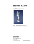
1
SBE 39 Temperature (pressure optional) Recorder With RS-232 Serial Interface Clamp optional With external thermistor & titanium housing User’s Manual Sea-Bird Electronics, Inc. 13431 NE 20th Street Bellevue, Washington 98005 USA Telephone: 425/643-9866 Fax: 425/643-9954 E-mail: [email protected] Website: www.seabird.com Manual Version #024, 02/04/13 Firmware Version 3.1b and later Limited Liability Statement Extreme care should be exercised when using or servicing this equipment. It should be used or serviced only by personnel with knowledge of and training in the use and maintenance of oceanographic electronic equipment. SEA-BIRD ELECTRONICS, INC. disclaims all product liability risks arising from the use or servicing of this system. SEA-BIRD ELECTRONICS, INC. has no way of controlling the use of this equipment or of choosing the personnel to operate it, and therefore cannot take steps to comply with laws pertaining to product liability, including laws which impose a duty to warn the user of any dangers involved in operating this equipment. Therefore, acceptance of this system by the customer shall be conclusively deemed to include a covenant by the customer to defend, indemnify, and hold SEA-BIRD ELECTRONICS, INC. harmless from all product liability claims arising from the use or servicing of this system. 2 Manual revision 024 Declaration of Conformity Declaration of Conformity 3 SBE 39 Manual Revision 024 Table of Contents SBE 39 Table of Contents Limited Liability Statement ............................................................................2 Declaration of Conformity ..............................................................................3 Table of Contents .............................................................................................4 Section 1: Introduction ....................................................................................6 About this Manual .............................................................................................6 Quick Start .........................................................................................................6 Unpacking SBE 39.............................................................................................7 Shipping Precautions .........................................................................................8 Section 2: Description of SBE 39 ....................................................................9 System Description ............................................................................................9 Specifications ...................................................................................................11 Dimensions and End Cap Connector ...............................................................12 Battery Endurance ............................................................................................13 External Power .................................................................................................13 Cable Length and External Power ............................................................13 Sample Timing .................................................................................................15 Section 3: Preparing SBE 39 for Deployment .............................................16 Software Installation ........................................................................................16 Power and Communications Test ....................................................................16 Test Setup .................................................................................................16 Test ...........................................................................................................18 Section 4: Deploying and Operating SBE 39 ...............................................22 Sampling Modes ..............................................................................................22 Polled Sampling ........................................................................................22 Autonomous Sampling (Logging commands) ..........................................23 Serial Line Sync ........................................................................................24 Real-Time Data Acquisition ............................................................................25 Command Descriptions ....................................................................................25 Data Output Formats ........................................................................................33 Setup for Deployment ......................................................................................34 Deployment ......................................................................................................35 Recovery ..........................................................................................................37 Uploading Data ................................................................................................38 Section 5: Routine Maintenance and Calibration .......................................43 Corrosion Precautions ......................................................................................43 External Connector Mating and Maintenance ..................................................43 Replacing Battery ............................................................................................44 Pressure Sensor (optional) Maintenance ..........................................................46 Sensor Calibration............................................................................................46 Temperature Sensor Calibration ...............................................................46 (optional) Pressure Sensor Calibration .....................................................46 4 Manual Revision 024 Table of Contents SBE 39 Glossary ..........................................................................................................47 Appendix I: Functional Description .............................................................48 Sensors .............................................................................................................48 Sensor Interface ...............................................................................................48 Real-Time Clock ..............................................................................................48 Memory............................................................................................................49 Appendix II: Plot39 Data Plotting Program................................................50 Appendix III: Command Summary .............................................................51 Appendix IV: Replacement Parts .................................................................53 Appendix V: Manual Revision History ........................................................55 Index................................................................................................................57 5 Manual Revision 024 Section 1: Introduction SBE 39 Section 1: Introduction This section includes a Quick Start procedure, photos of a standard SBE 39 shipment, and battery shipping precautions. About this Manual This manual is to be used with the SBE 39 Temperature (pressure optional) Recorder. It is organized to guide the user from installation through operation and data collection. We’ve included detailed specifications, command descriptions, maintenance and calibration information, and helpful notes throughout the manual. Sea-Bird welcomes suggestions for new features and enhancements of our products and/or documentation. Please contact us with any comments or suggestions ([email protected] or 425-643-9866). Our business hours are Monday through Friday, 0800 to 1700 Pacific Standard Time (1600 to 0100 Universal Time) in winter and 0800 to 1700 Pacific Daylight Time (1500 to 0000 Universal Time) the rest of the year. Quick Start Follow these steps to get a Quick Start using the SBE 39. The manual provides step-by-step details for performing each task: 1. Test Power and Communications (see Section 3: Preparing SBE 39 for Deployment). 2. Deploy the SBE 39 (see Section 4: Deploying and Operating SBE 39): A. Install a new battery if necessary. B. Set date and then time. C. Establish setup and sampling parameters. D. Ensure all data has been uploaded, and then set SampleNum=0 to make entire memory available for recording if desired. E. Check status (DS) and calibration coefficients (DC) to verify setup. F. Autonomous sampling: Set SBE 39 to start logging now or in the future. G. Install a new desiccant bag and close housing. H. Optional (bulkhead) I/O connector - Install dummy plug or I/O cable, and locking sleeve. I. Deploy SBE 39, using Sea-Bird mounting clamp or customersupplied hardware. 6 Manual Revision 024 Section 1: Introduction SBE 39 Unpacking SBE 39 A typical SBE 39 shipment is shown below (two of several available models are pictured). SBE 39 (with pressure) Plastic housing, sheathed temperature sensor SBE 39 (with pressure) Titanium housing, Embedded temperature sensor OR Standard I/O cable for internal I/O connector Optional I/O cable for external I/O bulkhead connector Spare parts kit – includes spare O-rings and (25) desiccant bags Software, and Electronic Copies of Software Manuals and User Manual 7 Manual Revision 024 Section 1: Introduction SBE 39 Shipping Precautions DISCLAIMER / WARNING: The shipping information provided in is a general overview of lithium battery shipping requirements; it does not provide complete shipping information. The information is provided as a courtesy, to be used as a guideline to assist properly trained shippers. These materials do not alter, satisfy, or influence any federal or state requirements. These materials are subject to change due to changes in government regulations. Sea-Bird accepts no liability for loss or damage resulting from changes, errors, omissions, or misinterpretations of these materials. See the current edition of the IATA Dangerous Good Regulations for complete information on packaging, labeling, and shipping document requirements. For its main power supply, the SBE 39 uses one 9-volt lithium battery (Duracell or Ultralife). The SBE 39 was shipped from the factory with the battery installed. If the shipment does not meet the requirements below, the shipment is considered Dangerous/Hazardous Goods, and must be shipped according to those rules. 1-2 SBE 39s and associated batteries, but no spares UN3091 1-2 SBE 39s and associated batteries, plus up to 2 spare batteries/SBE 39 UN3091 3-10 SBE 39s and associated batteries, but no spares 3-10 SBE 39s and associated batteries, plus up to 2 spare batteries/SBE 39 UN3091 Spares (without SBE 39s) Note new rules as of January 1, 2013 UN # UN3091 Packing Instruction (PI) 970 970 970 970 Must be shipped as # Class 9 Dangerous Passenger No No Yes Yes Goods. Aircraft If re-shipping spares, Cargo Aircraft Yes Yes Yes Yes you must have your Labeling own Dangerous Goods 1, 2 ** 1 ** 1, 2 ** Requirement program. Airway Bill (AWB) No Yes * Yes * Yes * Requirement * AWB must contain following information in Nature and Quantity of Goods Box: “Lithium Metal Batteries”, “Not Restricted”, “PI #” ** Labels are defined below: 2 xxx.xxxx.xxxx 1 – Shipper must provide an emergency phone number Note: Remove the battery before returning the SBE 39 to Sea-Bird. Do not return the used battery to Sea-Bird when shipping the SBE 39 for calibration or repair. All setup information is preserved when the battery is removed. If you will re-ship the SBE 39 after testing, pack the SBE 39 and/or spare batteries properly for shipment, apply appropriate labels, and prepare appropriate shipping documentation. 8 Manual Revision 024 Section 2: Description of SBE 39 SBE 39 Section 2: Description of SBE 39 This section describes the functions and features of the SBE 39, including specifications, dimensions, battery endurance, external power, and sample timing. System Description The SBE 39 is a high-accuracy temperature recorder (pressure optional) with internal battery and non-volatile memory, for deployment at depths up to 10500 meters (34,400 feet). The SBE 39 is intended for moorings or other long-term, fixed-site applications, as well as shorter-term deployments on nets, towed vehicles, or ROVs. The SBE 39’s optional cable clamp provides easy and secure attachment to a mooring cable. Calibration coefficients stored in EEPROM allow the SBE 39 to transmit data in engineering units. The SBE 39 retains the temperature sensor used in the SBE 16 SeaCAT and SBE 37 MicroCAT. The SBE 39’s thermistor has a long history of exceptional accuracy and stability (typical drift is less than 0.002 °C per year). Two temperature sensor configurations are offered: • Standard - ruggedized model with the thermistor embedded in the titanium end cap (time constant approximately 25 seconds). • Optional (shown in photo) - model with external thermistor in a pressureprotected sheath (time constant approximately 0.5 seconds) for use when fast sampling is required. Mooring wire clamp optional The SBE 39’s optional strain-gauge pressure sensor is available in the following ranges: 20, 100, 350, 600, 1000, 2000, 3500, and 7000 meters. Compensation of the temperature influence on pressure offset and scale is performed by the 39 CPU. The SBE 39 communicates directly with a computer via a standard RS-232 interface. Baud rates of 1200 to 38,400 are user-selectable. Commands can be sent to the SBE 39 to provide status display, data acquisition setup, data retrieval, and diagnostic tests. User-selectable operating modes include: • Polled sampling – The SBE 39 takes one sample and sends the data to the computer. Polled sampling is useful for integrating the SBE 39 with satellite, radio, or wire telemetry equipment. • Autonomous sampling – There are two types of Autonomous sampling. Interval sampling: At pre-programmed intervals, the SBE 39 wakes up, samples, stores data in memory, and powers off (enters quiescent state). Continuous sampling: The SBE 39 continuously samples and stores data in memory, and does not power off between samples. • Serial Line Sync - A pulse on the serial line causes the SBE 39 to wake up, sample, store data in memory, and power off. This mode provides easy integration with Acoustic Doppler Current Profilers (ADCPs) or current meters that can synchronize SBE 39 sampling with their own. 9 Manual Revision 024 Section 2: Description of SBE 39 SBE 39 Setup and extraction of data from the SBE 39 is dependent on the selected housing: • Standard housing with internal connector – open housing and plug data cable into the connector on the electronics assembly. • Optional housing with external waterproof connector – plug data cable into the external connector. Deployment depth is dependent on the selected housing: • Standard PET plastic housing - depths to 600 m (1960 ft) • Optional titanium housing - depths to 10,500 m (34,400 ft) The SBE 39 is available with optional mounting clamp(s) for mounting on a mooring wire. One clamp is used for typical applications; two clamps may be necessary if the mooring is subjected to high dynamic motion. The SBE 39 is also available with an optional net fender / fairing, with conical ends shaped to shed fishing lines and nets. When used with the net fender, two mounting clamps are required. The net fender is designed to retain half the mounting clamps. All hardware is captured within, guaranteeing no loss of nuts or bolts during deployment. Optional net fender / fairing Notes: • Help files provide detailed information on the software. • A separate software manual on CD-ROM contains detailed information on the setup and use of SBE Data Processing. • Sea-Bird supplies the current version of our software when you purchase an instrument. As software revisions occur, we post the revised software on our FTP site. See our website (www.seabird.com) for the latest software version number, a description of the software changes, and instructions for downloading the software from the FTP site. Future upgrades and enhancements to the SBE 39 firmware can be easily installed in the field through a computer serial port and the internal or external bulkhead connector on the SBE 39, without the need to return the SBE 39 to Sea-Bird. The SBE 39 is supplied with a powerful Windows software package, Seasoft V2, which includes: • Deployment Endurance Calculator– program for determining deployment length based on user-input deployment scheme, instrument power requirements, and battery capacity. • Seaterm - terminal program for easy communication and data retrieval. • Plot39 - program specifically for plotting SBE 39 data. • SBE Data Processing - SBE Data Processing includes many postprocessing modules; modules applicable to the SBE 39 are ASCII Out (export files for other programs) and SeaPlot (plot data). 10 Manual Revision 024 Section 2: Description of SBE 39 SBE 39 Specifications Temperature (°C) Measurement Range 0 to full scale range: 20 / 100 / 350 -5 to +35 / 600 / 1000 / 2000 / 3500 / 7000 m Pressure expressed in meters of deployment depth capability. Initial Accuracy 0.002 0.1% of full scale range Typical Stability 0.0002 per month 0.05% of full scale range per year Resolution 0.0001 0.002% of full scale range Sensor Calibration -1 to +32 Ambient pressure to full scale range in 5 steps 64 Mbyte non-volatile FLASH memory (32,900,000 bytes usable) Memory Data Storage Real-Time Clock Note: If the SBE 39 is logging data and the battery voltage is less than 6.25 volts for 10 consecutive scans, the SBE 39 halts logging and displays a low battery indication in the data. Pressure (optional) Internal Battery Converted temperature: 3 bytes per sample. Time: 4 bytes per sample. Pressure (optional): 2 bytes per sample. Recorded Parameters T and time T, P, and time Memory Space (total number of samples) 4,700,000 3,655,000 32,768 Hz TCXO accurate to ±1 minute/year Standard: 9-volt lithium battery (see Shipping Precautions in Section 1: Introduction) Optional: 9-volt alkaline transistor battery Quiescent Current: 10 microamps Current Consumption Current Consumption (per sample): T only: 0.018 amp-second T and P: 0.023 amp-second Current Consumption (continuous sampling): 15 milliamps Lithium battery: > 150,000 samples Battery Endurance Alkaline battery: > 41,000 samples Optional External Power 9-30 VDC (with external I/O connector) Standard: PET plastic pressure case rated at 600 meters (1960 feet) Materials Optional: Titanium pressure case rated at 10,500 meters (34,400 feet) Weight (without external connector, clamp, or fairing/net fender) 11 Plastic housing with embedded thermistor: In water: 0.25 kg (0.6 lbs) In air: 0.6 kg (1.2 lbs) Titanium housing with thermistor in sheath: In water: 0.7 kg (1.6 lbs) In air: 1.2 kg (2.6 lbs) Manual Revision 024 Section 2: Description of SBE 39 Dimensions and End Cap Connector The SBE 39 is available with an optional 4-pin XSG-4-BCL-HP-SS or MCBH-4MP (WB), TI (3/8” length base, ½-20 thread) (wet-pluggable) external connector. = XSG connector = MCBH (wet-pluggable) connector 12 SBE 39 Manual Revision 024 Section 2: Description of SBE 39 SBE 39 Battery Endurance Notes: • If the SBE 39 is logging data and the battery voltage is less than 6.25 volts for ten consecutive scans, the SBE 39 halts logging and displays a low battery indication in the data. • See Specifications above for data storage limitations. Battery capacity is as follows: • Standard lithium battery - nominal capacity is 1.2 amp-hours. For planning purposes, use a conservative value of 1.1 amp-hours. • Duracell MN1604 alkaline battery - nominal capacity is 0.4 amp-hours. For planning purposes, use a conservative value of 0.3 amp-hours. Current consumption is as follows: • Sampling (acquisition) current for continuous, autonomous sampling is 15 milliamps. • Sampling (acquisition) current for polled sampling; interval, autonomous sampling; or serial line sync sampling is 18 milliamp-seconds/sample for temperature and time, or 23 milliamp-seconds/sample for temperature, pressure, and time. • Quiescent current is 10 microamps (0.09 AH per year). So, battery endurance is highly dependent on the application. An example is shown below for two sampling schemes. For most cases, you can use the Deployment Endurance Calculator to determine the maximum deployment length, instead of performing the calculations by hand. Example 1: SBE 39 with pressure sensor is set up to sample autonomously every 5 minutes (12 samples/hour). How long can it be deployed with a lithium battery? Sampling current consumption = 23 milliamp-seconds/sample = 0.023 amp-seconds/sample In 1 hour, sampling current consumption = 12 * 0.023 amp-seconds/sample = 0.276 amp-seconds/hour Quiescent current = 10 microamps = 0.01 mA = 0.00001 amps In 1 hour, quiescent current consumption = 0.00001 mA * 3600 seconds/hour = 0.036 amp-seconds/hour Current consumption / hour = 0.276 + 0.036 = 0.312 amp-seconds/hour Capacity = (1.1 amp-hours * 3600 seconds/hr) / (0.312 amp-seconds/hour) = 12692 hours = 528 days = 1.45 years Total number of samples = 12692 hours * 12 samples/hour = 152,300 samples Example 2: SBE 39 with pressure sensor is set up to sample continuously. How long can it be deployed with a lithium battery? Sampling current consumption = 15 milliamps = 0.015 amps Capacity = (1.1 amp-hours) / (0.015 amps) = 73 hours External Power The SBE 39 can be externally powered during deployment if ordered with the optional external connector. The internal battery is diode-OR’d with the external source, so power is drawn from whichever voltage source is higher. Note: See Real-Time Data Acquisition in Section 4: Deploying and Operating SBE 39 for baud rate limitations on cable length if transmitting real-time data. Cable Length and External Power There are two issues to consider if powering the SBE 39 externally: • Limiting the IR loss to 1 volt if transmitting real-time data; higher IR loss will cause the SBE 39 to transmit data that does not meet the RS-232 communication standard. • Supplying enough power at the power source so that sufficient power is available at the instrument after considering IR loss. Looking at each issue separately: 13 Manual Revision 024 Note: Common wire resistances: Gauge 12 14 16 18 19 20 22 24 26 28 Resistance (ohms/foot) 0.0016 0.0025 0.0040 0.0064 0.0081 0.0107 0.0162 0.0257 0.0410 0.0653 Section 2: Description of SBE 39 SBE 39 Limiting IR Loss to 1 Volt if Transmitting Real-Time Data The limit to cable length is typically reached when the maximum current during communication times the power common wire resistance is more than 1 volt. V limit = 1 volt = IR limit Where I is the current required by the SBE 39 (15 milliamps for continuous sampling; see Specifications in Section 2: Description of SBE 39). Maximum cable length = R limit / wire resistance per foot Example 1 – For 24 gauge wire, what is the maximum distance to transmit power to the SBE 39 if sampling continuously? For 15 milliamp current, R limit = V limit / I = 1 volt / 0.015 amps = 67 ohms For 24 gauge wire, resistance is 0.0257 ohms/foot. Therefore, maximum cable length is 67 ohms / 0.0257 ohms/foot = 2594 feet = 790 meters Example 2 – Same as above, but there are 4 SBE 39s powered from the same power supply. For 15 milliamp current, R limit = V limit / I = 1 volt / (0.015 amps * 4 SBE 39s) = 17 ohms For 24 gauge wire, resistance is 0.0257 ohms/foot. Therefore, maximum cable length is 17 ohms / 0.0257 ohms/foot = 648 feet = 197 meters (this is the cable length to the SBE 39 furthest from the power source). Supplying Enough Power to SBE 39 Another consideration in determining maximum cable length is supplying enough power at the power source so that sufficient voltage is available, after IR loss in the cable, to power the SBE 39 without drawing battery power. Example 1 – For 24 gauge wire, what is the maximum distance to transmit power to the SBE 39 if using a 10.5 volt power source to supply power, and sampling continuously? The SBE 39’s input power specification is 9 – 30 volts. Conservatively, let’s assume a 10 volt minimum to avoid drawing power from the batteries. Therefore, a 0.5 volt IR drop (10.5 volts – 10 volts) would still provide enough power to the SBE 39. V = IR 0.5 volts = (0.015 amps) *(0.0257 ohms/foot * cable length) Cable length = 1297 ft = 395 meters Note that 395 meters < 790 meters (maximum distance if SBE 39 is transmitting real-time data), so the IR drop in power is the controlling factor for this example. Using a higher voltage power supply or a different wire gauge would increase the allowable cable length. Example 2 – Same as above, but there are 4 SBE 39s powered from the same power supply. V = IR 0.5 volts = (0.015 amps * 4 SBE 39s) *(0.0257 ohms/foot * cable length) (this is the cable length to the SBE 39 furthest from the power source) 14 Cable length = 324 ft = 98 meters Manual Revision 024 Section 2: Description of SBE 39 SBE 39 Sample Timing Note: Sampling time shown does not include time to transmit real-time data, which is dependent on baud rate. Minimum timing between samples is dependent on several factors, including: • Inclusion of optional pressure sensor in SBE 39 • Whether real-time output is provided (TxRealTime=) Time required to transmit data = The table below provides the approximate interval between samples if the SBE 39 is set up for continuous sampling: (# of characters * 10 bits/character) / baud This corresponds to 0.35 seconds at 1200 baud to 0.01 seconds at 38400 baud. Data Type (all include date and time) Temperature Temperature Temperature and Pressure Temperature and Pressure 15 Real-Time Output? No (TxRealTime=N) Yes (TxRealTime=Y) No (TxRealTime=N) Yes (TxRealTime=Y) Time (seconds) 0.80 1.00 1.25 1.50 Manual Revision 024 Section 3: Preparing SBE 39 for Deployment SBE 39 Section 3: Preparing SBE 39 for Deployment This section describes software installation and the pre-check procedure for preparing the SBE 39 for deployment. Software Installation Notes: • Help files provide detailed information on the software. A separate software manual on the CD-ROM contains detailed information on SBE Data Processing. • It is possible to use the SBE 39 without the Seaterm terminal program by sending direct commands from a dumb terminal or terminal emulator, such as Windows HyperTerminal. • Sea-Bird supplies the current version of our software when you purchase an instrument. As software revisions occur, we post the revised software on our FTP site. See our website (www.seabird.com) for the latest software version number, a description of the software changes, and instructions for downloading the software from the FTP site. Seasoft V2 was designed to work with a PC running Windows XP service pack 2 or later, Windows Vista, or Windows 7. If not already installed, install Sea-Bird software programs on your computer using the supplied software CD: 1. 2. 3. Insert the CD in your CD drive. Install software: Double click on SeasoftV2_date.exe (date is the date that version of the software was created). Follow the dialog box directions to install the software. The installation program allows you to install the desired components. Install all the components, or just install Deployment Endurance Calculator (battery endurance calculator), Seaterm (terminal program for the SBE 39), Plot39 (plotting software), and SBE Data Processing (data processing). Follow the dialog box directions to install the software. The default location for the software is c:\Program Files\Sea-Bird. Within that folder is a sub-directory for each program. Power and Communications Test Note: Sea-Bird ships the SBE 39 with a 9-volt battery installed. See Section 5: Routine Maintenance and Calibration to replace the battery. Temperature guard Wrench flats on end cap Test Setup 1. Connect to standard (non-bulkhead) internal I/O connector: A. Unscrew the plastic temperature guard, if applicable. Note: For SBE 39 with serial number 3000 and greater, you do not need to remove the temperature guard to use a wrench on the end cap’s wrench flats. B. Wipe the outside of the titanium end cap and housing dry, being careful to remove any water at the seam between them. C. Using a wrench on the end cap’s wrench flats, unscrew the end cap. 16 Manual Revision 024 Section 3: Preparing SBE 39 for Deployment SBE 39 D. Pull the end cap and attached electronics out of the housing. Note that the cardboard sleeve remains around the electronics. Molex connector E. Remove any water from the end cap O-rings and mating surfaces inside the housing with a lint-free cloth or tissue. F. Note: Before delivery, a desiccant bag is placed in the housing, and the electronics chamber is filled with dry Argon gas. These measures help prevent condensation. To ensure proper functioning: 1. Install a new desiccant bag each time you open the housing. If a new bag is not available, see Application Note 71: Desiccant Use and Regeneration (drying). 2. If possible, dry gas backfill each time you open the housing. If you cannot, wait at least 24 hours before redeploying, to allow the desiccant to remove any moisture from the chamber. Locking sleeve Dummy plug Pin 1 Ground Pin 2 Receive Pin 4 External power (optional) Pin 3 Transmit Pin Description 1 Ground - Computer data common 2 Receive - RS-232C receive data transmitted from computer 3 Transmit - RS-232C transmit data from SBE 39 to computer 4 Power - Optional external power (9-30 VDC) Remove the desiccant bag, which is attached to the PCB with a rubber band. G. Install the data I/O cable’s 6-pin Molex connector on the pins. Verify the connector is properly aligned – a backward connection will prevent communication with the computer. H. Connect the I/O cable connector to your computer’s serial port. I. 2. Optional (to power externally during setup): Connect the I/O cable battery terminal clip to a 9-volt battery. Connect to optional bulkhead I/O connector: A. By hand, unscrew the locking sleeve from the SBE 39’s bulkhead connector. If you must use a wrench or pliers, be careful not to loosen the bulkhead connector instead of the locking sleeve. B. Remove the dummy plug from the SBE 39’s bulkhead connector by pulling the plug firmly away from the connector. C. Install the Sea-Bird I/O cable connector: XSG Connector (shown in photos and illustration) - Align the raised bump on the side of the connector with the large pin (pin 1 - ground) on the SBE 39. OR MCBH Connector – Align the pins. D. Connect the I/O cable connector to your computer’s serial port. E. Optional (to power externally during setup): Connect the I/O cable battery terminal clip to a 9-volt battery. 17 Manual Revision 024 Section 3: Preparing SBE 39 for Deployment SBE 39 Test Note: See Seaterm’s Help files. 1. Double click on SeaTerm.exe. If this is the first time the program is used, the setup dialog box may appear: SBE39 Select the instrument type (SBE 39) and the computer COM port for communication with the SBE 39. Click OK. 2. The main screen looks like this: Menus Toolbar Command/Data Echo Area Status bar Instrument Note: There is at least one way, and as many as three ways, to enter a command: • Manually type a command in Command/Data Echo Area • Use a menu to automatically generate a command • Use a Toolbar button to automatically generate a command Note: Once the system is configured and connected (Steps 3 through 5 below), to update the Status bar: • on the Toolbar, click Status; or • from the Utilities menu, select Instrument Status. Seaterm sends the status command, which displays in the Command/Data Echo Area, and updates the Status bar. Computer COM port Instrument EPROM version • • • • Upload parameter Capture to file status – grayed out if not capturing Baud rate, data bits, stop bits, and parity Menus – Contains tasks and frequently executed instrument commands. Toolbar – Contains buttons for frequently executed tasks and instrument commands. All tasks and commands accessed through the Toolbar are also available in the Menus. To display or hide the Toolbar, select View Toolbar in the View menu. Grayed out Toolbar buttons are not applicable. Command/Data Echo Area – Echoes a command executed using a Menu or Toolbar button, as well as the instrument’s response. Additionally, a command can be manually typed in this area, from the available commands for the instrument. Note that the instrument must be awake for it to respond to a command (use Connect on the Toolbar to wake up the instrument). Status bar – Provides status information. To display or hide the Status bar, select View Status bar in the View menu. 18 Manual Revision 024 Section 3: Preparing SBE 39 for Deployment SBE 39 Following are the Toolbar buttons applicable to the SBE 39: Toolbar Button Description Re-establish communications with SBE 39. Computer responds with S> prompt. SBE 39 Connect goes to sleep after two minutes without communication from computer have elapsed. Display instrument setup and status (logging, Status number of samples in memory, etc.). Coefficients Display calibration coefficients. Capture instrument responses on screen to file. File has .cap extension. Press Capture again to Capture turn off capture. Capture status displays in Status bar. Upload Upload data stored in SBE 39’s memory, in format to allow for post-processing by Plot39 or SBE Data Processing. Uploaded data has .asc extension. Before using Upload: • Configure upload and header parameters in Configure menu • If Autonomous Sampling: Send Stop command to stop logging Equivalent Command* (press Enter key) DS DC — DDb,e or DBb,e (use Upload button if you will be processing data with Plot39 or SBE Data Processing) Convert uploaded ASCII data to .cnv data, which — can then be processed by SBE Data Processing. Perform one or more diagnostic tests on SBE 39. Diagnostic test(s) accessed in this manner are DS, DC, TS, Diagnostics non-destructive –they do not write over any and TSR existing instrument settings. Interrupt and end current activity, such as Stop — logging, uploading, or diagnostic test. Free computer COM port used to communicate Disconnect with SBE 39. COM port can then be used by — another program. *See Command Descriptions in Section 4: Deploying and Operating SBE 39. Convert 19 Manual Revision 024 Section 3: Preparing SBE 39 for Deployment 3. In the Configure menu, select SBE 39. The dialog box looks like this: Interface for communication between computer and SBE 39. Computer COM port, baud rate, data bits, and parity for communication between computer and SBE 39. Notes: • Seaterm’s baud rate must be the same as the SBE 39’s baud rate (set with Baud=). Baud= is factoryset to 9600, but can be changed by the user (see Command Descriptions in Section 4: Deploying and Operating SBE 39). • When you click OK, Seaterm saves the Configuration Options settings to the SeaTerm.ini file in your Windows directory. SeaTerm.ini contains the last saved settings for each instrument. When you open Seaterm and select the desired instrument (SBE 37, 39, etc.) in the Configure menu, the Configuration Options dialog box shows the last saved settings for that instrument. SBE 39 Make the selections in the Configuration Options dialog box: • COMM Port: COM 1 through COM 10, as applicable • Baud Rate: 9600 (documented on Configuration Sheet) • Data Bits: 8 • Parity: None • Mode: RS-232 (Full Duplex) Click OK to save the settings. 4. In the Communications menu, select Options / Cycle baud when connecting. 5. Click Connect on the Toolbar. Seaterm tries to connect to the SBE 39 at the baud set in Step 3. If it cannot, it cycles through all other possible baud rates to try to connect. When it connects, the display looks like this: SBE 39 S> This shows that correct communications between the computer and the SBE 39 has been established. If the system does not respond as shown above: • Click Connect again. • Verify the correct instrument was selected in the Configure menu and the settings were entered correctly in the Configuration Options dialog box. Note that the baud rate’s factory setting is documented on the Configuration Sheet in this manual. • Check cabling between the computer and SBE 39. 20 Manual Revision 024 Section 3: Preparing SBE 39 for Deployment 6. Note: The SBE 39 has a 2-minute timeout algorithm designed to: • restore control to the computer if an illegal command is sent • conserve battery energy if too much time elapses between commands If the system does not appear to respond, click Connect on the Toolbar to reestablish communications. SBE 39 Display SBE 39 status information by clicking Status on the Toolbar. The display looks like this: SBE 39 V 3.1 SERIAL NO. 4355 21 Apr 2008 08:49:08 battery voltage = 9.1 logging not started sample interval = 20 seconds samplenumber = 0, free = 3655452 serial sync mode disabled real-time output disabled SBE 39 configuration = temperature with pressure binary upload includes time temperature =19.48 deg C 7. Command the SBE 39 to take a sample by typing TS and pressing the Enter key. The display looks like this: 19.5058, 0.062, 21 Apr 2008, 08:50:43 where 19.5058 = temperature in degrees Celsius 0.062 = pressure in dbars 21 Apr 2008 = date 08:50:43 = time These numbers should be reasonable; i.e., room temperature, barometric pressure (gauge pressure), current date and time (factory-programmed to Pacific Daylight or Standard Time; can be changed by user). 8. Command the SBE 39 to go to sleep (quiescent state) by typing QS and pressing the Enter key. The SBE 39 is ready for programming and deployment. 21 Manual Revision 024 Section 4: Deploying and Operating SBE 39 SBE 39 Section 4: Deploying and Operating SBE 39 This section provides instructions / discussions on: • system operation • example sets of operation commands for each operating mode • real-time data acquisition • detailed command descriptions • data output formats • deployment • uploading data • processing data Sampling Modes The SBE 39’s user-selectable sampling modes for obtaining data include: • Polled Sampling • Autonomous Sampling - Interval and Continuous • Serial Line Synchronization Commands can be used in various combinations to provide a high degree of operating flexibility. Descriptions and examples of the sampling modes follow. Note that the SBE 39’s response to each command is not shown in the examples. Review the operation of the sampling modes and the commands described in Command Descriptions before setting up your system. Polled Sampling The SBE 39 takes one sample of data and sends the data to the computer. Storing of data in the SBE 39’s FLASH memory is dependent on the particular command used. Example: (user input in bold) Establish communication with SBE 39. Command SBE 39 to take a sample and send converted data to computer (do not store data in memory). Send power-off command to SBE 39. (Click Connect on Toolbar) S>TS S>QS 22 Manual Revision 024 Section 4: Deploying and Operating SBE 39 SBE 39 Autonomous Sampling (Logging commands) There are two types of Autonomous sampling: Note: Use Stop to: • stop logging • stop waiting to start logging (after StartLater has been sent) • Interval sampling: At pre-programmed intervals, the SBE 39 wakes up, samples data and stores it in FLASH memory, and powers-off (enters quiescent state). The sampling interval is set with Interval=. • Continuous sampling: The SBE 39 samples data continuously and stores it in FLASH memory, and does not power-off between samples. Continuous sampling is established by setting Interval=0. See Sample Timing in Section 2: Description of SBE 39 for approximate time between each sample. Logging is started with StartNow or StartLater, and is stopped with Stop. Transmission of real-time data to the computer is dependent on TxRealTime=. Example: Autonomous Sampling - Interval Sampling (user input in bold) Establish communication. Set sample number to 0 to overwrite previous data in memory. Set up to sample every 10 seconds and store data in memory, and not transmit real-time data to computer. Set up to automatically start on 10 January 2009 at 12:00:00. Send power-off command after all parameters are entered - system will automatically wake up and power down for each sample. (Click Connect on Toolbar to wake up) S>SAMPLENUM=0 S>INTERVAL=10 S>TXREALTIME=N S>STARTMMDDYY=011009 S>STARTHHMMSS=120000 S>STARTLATER S>DS (to verify setup) S>QS When ready to upload all data to computer, establish communication, stop sampling, and upload data. Send power-off command. (Click Connect on Toolbar) (Press Enter key to get S> prompt) S>STOP (Click Upload on Toolbar – program leads you through screens to define data to be uploaded and where to store it) S>QS Example: Autonomous Sampling - Continuous Sampling Same as above, but set INTERVAL=0. 23 Manual Revision 024 Section 4: Deploying and Operating SBE 39 SBE 39 Serial Line Sync Serial Line Sync allows a simple pulse on the RS-232 line to initiate a sample. This mode provides easy integration with ADCPs or current meters, which can synchronize SBE 39 sampling with their own without drawing on their battery or memory resources. If this mode is enabled (SyncMode=Y) and the SBE 39 is powered down, setting the RS-232 RX line high (3 –10 VDC) for 1 to 1000 milliseconds wakes up the SBE 39 and executes the following sequence: • Take sample • Store sample in FLASH memory • Output real-time data if TxRealTime=Y Note: If running Seaterm, select Send 5 second break in the Communications menu to hold the RS-232 RX line in space state for 5 seconds. This will cause the SBE 39 to exit Serial Line Sync Mode. The SBE 39 then checks the RS-232 line: • Mark State (RS-232 RX line less than 0.5 volts) SBE 39 immediately powers down. Serial line sync mode remains enabled (SyncMode=Y). • Space State (RS-232 RX line greater than 3 volts) SBE 39 monitors the RS-232 line for 100 milliseconds: If line remains in space state - SBE 39 disables serial line sync mode (SyncMode=N) at end of time. Once serial line sync mode is disabled, you can communicate with the SBE 39 using the full range of commands (setup, autonomous sampling, upload commands, etc.). If line returns to mark state - SBE 39 immediately powers down. Serial line sync mode remains enabled (SyncMode=Y). In summary, to disable serial line sync after taking a sample, put the RS-232 line in space state (greater then 3 volts) for 100 milliseconds. Example: Serial Line Sync Mode (user input in bold) Establish communication. Set sample number to 0 to overwrite previous data in memory. Do not transmit real-time data to computer. Enable serial line sync mode. Send power off command. (Click Connect on Toolbar to wake up) S>SAMPLENUM=0 S>TXREALTIME=N S>SYNCMODE=Y S>DS (to verify setup) S>QS Take samples using serial line sync mode: (Set RS-232 RX line high [3-10 VDC] for 1-1000 milliseconds. SBE 39 takes sample and stores data in memory. Within 100 milliseconds, set RS-232 RX line to mark state [less than 0.5 volts]; SBE 39 powers down.) (Repeat this process at periodic intervals as desired.) When ready to upload all data to computer, disable serial line sync mode, and then upload data and power down: (Set RS-232 RX line high [3-10 VDC] for 1-1000 milliseconds. SBE 39 takes sample and stores data in memory) (Select Send 5 second break in Communications menu to disable serial line sync mode.) (Press Enter key to get S> prompt.) S>DS (to verify SBE 39 is communicating) (Click Upload on Toolbar – program leads you through screens to define data to be uploaded and where to store it) S>QS 24 Manual Revision 024 Section 4: Deploying and Operating SBE 39 SBE 39 Real-Time Data Acquisition Notes: • Set TxRealTime=Y to transmit real-time data for autonomous sampling or serial line sync mode. Set baud rate with Baud=. See Command Descriptions in this section for command details. • If using external power, see External Power in Section 2: Description of SBE 39 for power limitations on cable length. The length of cable that the SBE 39 can drive for transmitting real-time data is dependent on the baud rate. Allowable combinations are: Maximum Cable Length (meters) 800 400 200 100 50 25 Maximum Baud Rate 1200 2400 4800 9600 19200 38400 If acquiring real-time data, click Capture on Seaterm’s Toolbar before you begin sampling. The data displayed in Seaterm will be saved to the designated file. Process the data as desired. Note that this real-time data file cannot be processed by Plot39 or SBE Data Processing, as it does not have the required headers and format. To process data with Plot39 or SBE Data Processing, upload the data from the SBE 39’s memory. Command Descriptions This section describes commands and provides sample outputs. See Appendix III: Command Summary for a summarized command list. When entering commands: • • • • • Input commands to the SBE 39 in upper or lower case letters and register commands by pressing the Enter key. The SBE 39 sends ? CMD if an invalid command is entered. If the system does not return an S> prompt after executing a command, press the Enter key to get the S> prompt. If a new command is not received within two minutes after the completion of a command, the SBE 39 returns to the quiescent (sleep) state to prevent exhaustion of its battery. If in quiescent state, re-establish communications by clicking Connect on the Toolbar or pressing the Enter key to get an S> prompt. 25 Manual Revision 024 Section 4: Deploying and Operating SBE 39 SBE 39 Status Command DS Display status and setup parameters. Equivalent to Status on Toolbar. List below includes, where applicable, command used to modify parameter. • firmware version, serial number, date and time [MMDDYY= and HHMMSS=] • remaining battery voltage • autonomous sampling status (logging not started, logging data, not logging: waiting to start at … , not logging: received stop command, not logging: low battery, or unknown status) • sample interval time [Interval=] • number of samples in memory and available sample space in memory • serial line sync mode status [SyncMode=] • real-time output status [TxRealTime=] • configuration (temperature only or temperature with pressure) • binary upload includes time? [BinaryTime=] • current temperature Example: (user input in bold, command used to modify parameter in parentheses). S>DS SBE39 V 3.1 SERIAL NO. 4355 21 Apr 2008 08:49:08 battery voltage = 9.1 logging not started sample interval = 20 seconds samplenumber = 2, free = 3655450 serial sync mode disabled real-time output disabled SBE 39 configuration = temperature with pressure binary upload includes time temperature = 19.48 deg C 26 [MMDDYY= and HHMMSS=] [Interval=] [SyncMode=] [TxRealTime=] [BinaryTime=] Manual Revision 024 Section 4: Deploying and Operating SBE 39 SBE 39 Notes: • DDMMYY= and MMDDYY= are equivalent. Either can be used to set the date. • Always set date and then time. If a new date is entered but not a new time, the new date will not be saved. If a new time is entered without first entering a new date, the date will reset to the last date it was set for with MMDDYY= or DDMMYY=. • If the battery has been removed, date and then time must be reset. • If the SBE 39 is logging or waiting to start logging (StartLater has been sent), it will not allow the user to reset date or time. Setup Commands Note: The SBE 39’s baud (set with Baud=) must be the same as Seaterm’s baud (set in Configure menu). Baud=x x= baud rate (1200, 2400, 4800, 9600, 19200, 38400). Default 9600. Notes: • TxRealTime= applies to autonomous (continuous or interval sampling) and serial line sync mode. • To capture real-time data to a file, do this before starting logging: A. Click Toolbar’s Capture button. B. Enter desired file name in dialog box. Capture status displays in status bar at bottom of screen. TxRealTime=x x=Y: Output real-time data to computer. Data is transmitted immediately after it is sampled. This does not affect storing data to FLASH memory, but slightly increases current consumption and increases amount of time needed to sample (and then transmit) data. MMDDYY=mmddyy Set real-time clock month, day, year. Must be followed by HHMMSS= to set time. DDMMYY=ddmmyy Set real-time clock day, month, year. Must be followed by HHMMSS= to set time. HHMMSS=hhmmss Set real-time clock hour, minute, second. Example: Set current date and time to 10 July 2008 12:00:00 (user input in bold). S>MMDDYY=071008 S>HHMMSS=120000 or S>DDMMYY=100708 S>HHMMSS=120000 x=N: Do not. SyncMode=x x=Y: Enable Serial Line Sync Mode. When RS-232 RX line is high (3-10 VDC) for 1 to 1000 milliseconds, SBE 39 takes a sample, stores data in FLASH memory, transmits real-time data (if TxRealTime=Y), and powers down. Note: See Sampling Modes for details on serial line synchronization. x=N: Do not. Note: Do not send SampleNum=0 until all data has been uploaded. SampleNum=0 does not delete data; it just resets the data pointer. If you accidentally send this command before uploading, see Memory in Appendix I: Functional Description for a discussion of how to recover the data. SampleNum=x x= sample number for first sample when sampling begins. After all previous data has been uploaded from SBE 39, set sample number to 0 before starting to sample to make entire memory available for recording. If not set to 0, data will be stored after last recorded sample. QS Quit session and place SBE 39 in quiescent (sleep) state. Main power is turned off. Autonomous sampling and memory retention are unaffected, with one exception: If Interval=0 (continuous sampling), do not send QS after sending StartNow (QS puts SBE 39 to sleep, preventing further autonomous sampling). 27 Manual Revision 024 Section 4: Deploying and Operating SBE 39 SBE 39 Autonomous Sampling (Logging) Commands Note: If the SBE 39 is logging data and the battery voltage is less than 6.25 volts for ten consecutive scans, the SBE 39 halts logging and sets the logging status to low battery. Autonomous sampling commands direct the SBE 39 to sample data at preprogrammed intervals and store the data in its FLASH memory. Interval=x x= interval (seconds) between samples (0, or 3 to 32767). When commanded to start sampling with StartNow or StartLater, SBE 39 takes a sample, stores data in FLASH memory, transmits realtime data (if TxRealTime=Y), and powers down at x second intervals. Note: Sampling time shown does not include time to transmit real-time data, which is dependent on baud rate: Time required to transmit data = (# of characters * 10 bits/character) / baud This corresponds to 0.35 sec at 1200 baud to 0.01 sec at 38400 baud. Note: If Interval=0 (continuous sampling), do not send QS after sending StartNow. QS puts the SBE 39 to sleep, preventing further logging. Note: StartDDMMYY= and StartMMDDYY= are equivalent. Either can be used to set the delayed start date. Notes: • After receiving StartLater, the SBE 39 displays not logging: waiting to start in reply to DS. Once logging has started, the DS reply indicates logging data. • If the delayed start time has already passed when StartLater is received, the SBE 39 executes StartNow. Note: You may need to send Stop several times to get the SBE 39 to respond. This is most likely to occur if sampling continuously or with a small Interval and transmitting real-time data (TxRealTime=Y). If x=0, SBE 39 samples continuously without powering down between samples. Approximate interval between samples: Data Type (all include date and time) Temperature Temperature Temperature and Pressure Temperature and Pressure Real-Time Output? No (TxRealTime=N) Yes (TxRealTime=Y) No (TxRealTime=N) Yes (TxRealTime=Y) Time (seconds) 0.80 1.00 1.25 1.50 StartNow Start logging now, storing data in FLASH memory. Data is transmitted real-time if TxRealTime=Y. StartMMDDYY=mmddyy Set delayed logging start month, day, and year. Must be followed by StartHHMMSS= to set delayed start time. StartDDMMYY=ddmmyy Set delayed logging start day, month, and year. Must be followed by StartHHMMSS= to set delayed start time. StartHHMMSS=hhmmss Set delayed logging start hour, minute, and second. StartLater Start logging at time set with delayed start date and time commands, storing data in FLASH memory. Data is transmitted realtime if TxRealTime=Y. Example: Program SBE 39 to start logging on 20 January 2009 12:00:00 (user input in bold). S>STARTMMDDYY=012009 S>STARTHHMMSS=120000 S>STARTLATER or S>STARTDDMMYY=200109 S>STARTHHMMSS=120000 S>STARTLATER Stop Stop logging (started with StartNow or StartLater) or stop waiting to start logging (if StartLater was sent but logging has not begun yet). Press Enter key to get S> prompt before entering Stop. Stop must be sent before uploading data using Upload on Toolbar, Upload Data in Data menu, or DDb,e or DBb,e. 28 Manual Revision 024 Section 4: Deploying and Operating SBE 39 SBE 39 Polled Sampling Commands Note: The SBE 39 has a buffer that stores the most recent data sample. Unlike data in the FLASH memory, data in the buffer is erased upon removal or failure of the battery. These commands are used by an external controller to request a sample from the SBE 39. TS Take sample and transmit converted data. Data is not stored in FLASH memory. Do not send if SBE 39 is logging data. TSR Take sample and transmit raw data. Data is not stored in FLASH memory. Do not send if SBE 39 is logging data. SLT Transmit converted data from last sample from buffer, and then take new sample. Data is not stored in FLASH memory. Do not send if SBE 39 is logging data. SLTR Transmit raw data from last sample from buffer, and then take new sample. Data is not stored in FLASH memory. Do not send if SBE 39 is logging data. TSS Take sample, store in FLASH memory, transmit converted data, and turn power off. Do not send if SBE 39 is logging data. TSSON Take sample, store in FLASH memory, transmit converted data. Do not send if SBE 39 is logging data. SL Transmit converted data from last sample from buffer. 29 Manual Revision 024 Section 4: Deploying and Operating SBE 39 SBE 39 Data Upload Commands Send Stop before uploading data. Notes: • Manually entering DDb,e or DBb,e does not produce data with the required header information for processing by Plot39 or SBE Data Processing. Use Upload on the Toolbar or Upload Data in the Data menu to upload data that will be processed by Plot39 or SBE Data Processing; Seaterm checks the setting on the Upload Settings tab in the Configuration dialog box to determine whether to upload in ASCII or binary format. • To save data to a file, click Capture on the Toolbar before entering DDb,e or DBb,e. • See Data Output Formats after these Command Descriptions. ASCII Upload: DDb,e Upload data from scan b to scan e. First scan is number 1. If DDb is sent, only scan b is uploaded. If DD is sent, all scans in memory are uploaded. As data uploads, screen first displays start time =, sample interval =, and start sample number = . These are start time, sample interval, and starting sample number for last set of logged data, which can be useful in determining what data to review. Examples: Upload data from memory (user input in bold). (Click Capture on Toolbar and enter desired filename in dialog box before beginning upload.) S>DD1,200 (Upload scans 1 through 200) S>DD1 (Upload scan 1) S>DD (Upload all scans in memory) Binary Upload: Binary upload, useful for large data sets, is faster than ASCII upload. Seaterm uploads the data in binary and then converts to ASCII engineering units, resulting in a .asc file with the same format as from an ASCII upload. Seaterm uses the following relationships to convert the binary data back to ASCII engineering units: t = (T / tscale) - toffset p= (P / pscale) - poffset time (binary) = seconds since 1980 Note: If Interval=0 (continuous sampling) and uploading data in binary, verify that BinaryTime=Y before you start the upload. If BinaryTime=N, Seaterm will insert the same date and time for every scan in the upload block. where - tscale, toffset, pscale, and poffset are factory-programmed into the SBE 39 - T and P are binary representations of temperature and pressure - t and p are temperature and pressure in ASCII engineering units DBb,e Upload data in binary from scan b to scan e. First scan is number 1. If DBb is sent, only scan b is uploaded. If DB is sent, all scans in memory are uploaded. As data uploads, screen first displays start time =, sample interval =, and start sample number = . These are start time, sample interval, and starting sample number for last set of logged data, which can be useful in determining what data to review. Example: Upload data from memory (user input in bold). (Click Capture on Toolbar and enter desired filename in dialog box before beginning upload.) S>DB1,200 (Upload scans 1 through 200) S>DB1 (Upload scan 1) S>DB (Upload all scans in memory) 30 Manual Revision 024 Section 4: Deploying and Operating SBE 39 SBE 39 Data Upload Commands (continued) Note: BinaryTime= has no effect on the standard ASCII upload. BinaryTime=x Applies to binary data upload only. x=Y: Upload date and time for every scan from memory. x=N: Upload date and time from memory only for scan at beginning of each block of data (350 scans/block), reducing time required for upload. Seaterm uses Interval= to calculate and insert date and time for each scan within block. If SBE 39 did not sample at correct interval, any discrepancy will be apparent by comparing calculated time for last scan in a data block to uploaded time for first scan in following data block. Do not set BinaryTime=N if Interval=0 (continuous sampling); Seaterm will insert same date and time for every scan in block. *DB Display binary upload parameters. Each parameter is separated by a comma and a space. List below includes, where applicable, command used to modify parameter. • Sample interval time [Interval=] • Type SBE 39 BinaryTime= Type Configuration T only N 0 T&P N 1 T only Y 2 T&P Y 4 • Tscale, toffset, pscale, and poffset factory-programmed parameters used to convert binary data from SBE 39 back to ASCII engineering units 31 Manual Revision 024 Section 4: Deploying and Operating SBE 39 SBE 39 Testing Commands Data obtained with these commands is not stored in FLASH memory. TT Measure temperature for 100 samples or until Esc key is pressed, output converted data. TP Measure pressure and pressure temperature for 100 samples or until Esc key is pressed, output converted data. TTR Measure temperature for 100 samples or until Esc key is pressed, output raw data. TPR Measure pressure and pressure temperature for 100 samples or until Esc key is pressed, output raw data. Calibration Coefficients Commands Notes: • Dates shown are when calibrations were performed. Calibration coefficients are initially factory-set and should agree with Calibration Certificates shipped with SBE 39. • See individual Coefficient Commands below for definitions of the data in the example. DC Display calibration coefficients. Equivalent to Coefficients on Toolbar. Example: Display coefficients for SBE 39 without a pressure sensor (user input shown in bold). S>DC SBE39 V 3.1 04355 temperature: 08-apr-08 TA0 = -9.420702e-05 TA1 = 2.937924e-04 TA2 = -3.739471e-06 TA3 = 1.909551e-07 Individual Coefficient Commands listed below modify a particular coefficient or date: Note: F = floating point number S = string with no spaces Temperature TCalDate=S TA0=F TA1=F TA2=F TA3=F S=Temperature calibration date F=Temperature A0 F=Temperature A1 F=Temperature A2 F=Temperature A3 Pressure PCalDate=S PA0=F PA1=F PA2=F PTHA0=F PTHA1=F PTHA2=F PTCA0=F PTCA1=F PTCA2=F PTCB0=F PTCB1=F PTCB2=F S=Pressure calibration date F=Pressure A0 F=Pressure A1 F=Pressure A2 F=Thermistor coefficient A0 F=Thermistor coefficient A1 F=Thermistor coefficient A2 F=Pressure ptca0 F=Pressure ptca1 F=Pressure ptca2 F=Span TC b0 F=Span TC b1 F=Span TC b2 32 Manual Revision 024 Section 4: Deploying and Operating SBE 39 SBE 39 Data Output Formats The SBE 39 transmits data in engineering units (except for in response to TSR and SLTR, which request raw data). The output format varies, as described below. Notes: • Each line of output is followed by a carriage return and line feed. • Leading zeros for temperature and pressure output are suppressed, except for one zero to the left of the decimal point (for example, a temperature of 0.1034). Note: If Interval=0 (continuous sampling) and uploading data in binary, verify that BinaryTime=Y before you start the upload. If BinaryTime=N, Seaterm will insert the same date and time for every scan in the upload block. • Output to Seaterm after Sending Polled Sampling Command (TS, SL, SLT, TSS, TSSON) ttt.tttt, pppp.ppp, dd mmm yyyy, hh:mm:ss • Output to Seaterm if Transmitting Real-Time Data from Autonomous or Serial Line Sync Sampling (TxRealTime=Y) # ttt.tttt, pppp.ppp, dd mmm yyyy, hh:mm:ss • Output to Seaterm after Manually Sending ASCII Data Upload Command (DDb,e) ttt.tttt, pppp.ppp, dd mmm yyyy, hh:mm:ss • Output to Seaterm after Manually Sending Binary Data Upload Command (DBb,e) - not usable • Output to .asc file after Sending Data Upload Command with Upload on Toolbar or Upload Data in Data menu ttt.tttt, pppp.ppp, dd mmm yyyy, hh:mm:ss Note: This applies to ASCII as well as binary upload. Where: t = temperature (degrees Celsius, ITS-90) p = pressure (decibars); data sent only if optional pressure sensor is installed. Note: The SBE 39 outputs pressure relative to the ocean surface (i.e., at the surface the output pressure is 0 decibars). However, the pressure sensor is an absolute sensor, so its raw output includes the effect of atmospheric pressure (14.7 psi). Additionally, as shown on the Calibration Sheet, Sea-Bird’s calibration (and resulting calibration coefficients) is in terms of psia. The SBE 39 uses the following equation to convert psia to decibars: pressure (decibars) = [pressure (psia) - 14.7] * 0.689476 hh:mm:ss = hour, minute, second dd mmm yyyy = day, month, year The month is a 3-character alphabetic abbreviation; e.g., jan, feb, mar, etc. 33 Manual Revision 024 Section 4: Deploying and Operating SBE 39 SBE 39 Setup for Deployment 1. Install a new battery (see Section 5: Routine Maintenance and Calibration) or ensure the existing battery has enough capacity to cover the intended deployment. 2. Program the SBE 39 for the intended deployment (see Section 3: Preparing SBE 39 for Deployment for connection information; see information in this section on commands and sampling modes): Notes: • If the battery has been removed, date and then time must be reset. • It is always necessary to set both date and then time. A. Set the date and then time. B. Establish the setup and sampling parameters. C. Ensure all data has been uploaded, and then set SampleNum=0 to make the entire memory available for recording. If SampleNum= is not reset to 0, data will be stored after the last recorded sample. D. Use one of the following sequences to initiate logging: • StartNow to start logging now, taking a sample every Interval= seconds. • StartMMDDYY=, StartHHMMSS=, and StartLater to start logging at the specified date and time, taking a sample every Interval= seconds. • SyncMode=Y to place the SBE 39 in serial line sync mode, so that a simple pulse on the RS-232 line will initiate a sample. Note: If Interval=0, the SBE 39 samples continuously, without powering down between samples. Note: Before delivery, a desiccant bag is placed in the housing, and the electronics chamber is filled with dry Argon gas. These measures help prevent condensation. To ensure proper functioning: 1. Install a new desiccant bag each time you open the housing. If a new bag is not available, see Application Note 71: Desiccant Use and Regeneration (drying). 2. If possible, dry gas backfill each time the electronics are exposed to the atmosphere. If you cannot, wait at least 24 hours before redeploying, to allow the desiccant to remove any moisture from the chamber. 3. Close the housing if it was opened to install a battery or program an SBE 39 with Standard (non-bulkhead) Internal I/O Connector Reinsert the electronics in the housing and close the housing, as described in Replacing Battery in Section 5: Routine Maintenance and Calibration. 34 Manual Revision 024 Section 4: Deploying and Operating SBE 39 SBE 39 Deployment Air space around embedded thermistor CAUTION: Do not use WD-40 or other petroleum-based lubricants, as they will damage the connector. For an SBE 39 with an embedded (internal) thermistor, there is a depression in the end cap around the thermistor. Do not deploy the SBE 39 with the end cap up, as sediment and/or non-flushing water can get trapped in this space, affecting the response of the thermistor. The SBE 39 can be ordered with one or more Sea-Bird mounting clamps for mounting on a mooring cable; two clamps are recommended if the mooring is subjected to high dynamic motion (at least one Sea-Bird mooring clamp is required if installing with the optional net fender/fairing). Alternatively, the SBE 39 can be mounted with customer-supplied hardware. 1. Install the dummy plug or I/O cable for SBE 39 with optional bulkhead I/O connector: A. Lightly lubricate the inside of the dummy plug or cable connector with silicone grease (DC-4 or equivalent). B. XSG Connector (shown in photo) - Install the dummy plug or cable connector, aligning the raised bump on the side of the plug/connector with the large pin (pin 1 - ground) on the SBE 39. Remove any trapped air by burping or gently squeezing the plug/connector near the top and moving your fingers toward the end cap. OR MCBH Connector – Install the plug/cable connector, aligning the pins. C. Place the locking sleeve over the plug/connector. Tighten the locking sleeve finger tight only. Do not overtighten the locking sleeve and do not use a wrench or pliers. 2. Mount the SBE 39, using customer-supplied hardware. If using Sea-Bird’s optional mounting clamp(s), or Sea-Bird’s optional fairing / net fender, see below. 3. Verify that the hardware and external fittings are secure. Dummy plug or I/O cable connector Locking sleeve SBE 39 with Optional Mounting Clamp(s) Tighten hex bolts to install on mooring cable Tighten to ensure clamp is secure on SBE 39 housing Use one or two clamps; two clamps are recommended if the mooring is subjected to high dynamic motion. 1. Attach the mounting clamp(s) to the mooring cable. A. Open the mounting clamp(s) by unthreading the two large titanium hex bolts. B. Place the mooring cable inside the clamps’ grooves. C. Reinstall each clamp half with the hex bolts. 2. Verify that the hardware and external fittings are secure. SBE 39 with optional Sea-Bird clamp – use 1 or 2 clamps 35 Manual Revision 024 Section 4: Deploying and Operating SBE 39 SBE 39 SBE 39 with Optional Net Fender / Fairing Optional net fender / fairing The optional net fender requires the use of two Sea-Bird mounting clamps. 1. Remove the SBE 39 from the net fender: A. Insert a 3/16 inch Allen wrench through the countersunk holes in the back of the net fender to loosen the four mounting clamp bolts (two for each clamp). Note: Do not remove the other bolts, which are used to retain the clamp halves in the net fender. B. When all four bolts (two for each clamp) are loosened, remove the SBE 39 from the net fender. Note: The other half of the mounting clamps remain attached to the Loosen bolts through net fender, and the mounting bolts remain attached to the retained countersunk portions of the clamps. holes in fairing (2 bolts each clamp) Countersunk holes 2. Install the SBE 39 and net fender on the mooring cable: Note: If desired, you can adjust the location of the clamps on the SBE 39 before installing on the mooring cable. The clamps must line up with two of the locations on the net fender, as shown below. Align clamp mounting holes here Tighten bolts through holes in net fender (2 bolts each clamp) Align clamp mounting holes in one of these locations A. Bringing the SBE 39 and the net fender together, place the mooring cable inside the clamps’ grooves. B. Use a 3/16 inch Allen wrench to tighten the four mounting clamp bolts through the countersunk holes in the back of the net fender. 3. Verify that the hardware and external fittings are secure. 36 Manual Revision 024 Section 4: Deploying and Operating SBE 39 Recovery WARNING! If the 39 stops working while underwater, is unresponsive to commands, or shows other signs of flooding or damage, carefully secure it away from people until you have determined that abnormal internal pressure does not exist or has been relieved. Pressure housings may flood under pressure due to dirty or damaged o-rings, or other failed seals. When a sealed pressure housing floods at great depths and is subsequently raised to the surface, water may be trapped at the pressure at which it entered the housing, presenting a danger if the housing is opened before relieving the internal pressure. Instances of such flooding are rare. However, a housing that floods at 5000 meters depth holds an internal pressure of more than 7000 psia, and has the potential to eject the end cap with lethal force. A housing that floods at 50 meters holds an internal pressure of more then 85 psia; this force could still cause injury. If you suspect the 39 is flooded, point it in a safe direction away from people: • SBE 39 with external connector: Loosen the bulkhead connector very slowly, at least 1 turn. This opens an o-ring seal under the connector. Look for signs of internal pressure (hissing or water leak). If internal pressure is detected, let it bleed off slowly past the connector o-ring. Then, you can safely remove the end cap. • SBE 39 with internal connector, Serial Number 3000 and greater: Slowly turn the end cap ¼ turn at a time (using a wrench on the end cap’s wrench flats), letting the internal pressure bleed off slowly past the o-rings as the o-rings are released from the housing. Then, you can completely remove the end cap and electronics from the housing. • SBE 39 with internal connector, Serial Number less than 3000: Carefully secure it in a location away from people. Contact Sea-Bird for assistance. Rinse the SBE 39 with fresh water, and dry thoroughly. 37 SBE 39 Manual Revision 024 Section 4: Deploying and Operating SBE 39 SBE 39 Uploading Data Note: While uploading data, Warning: Low Battery Voltage may be displayed. Follow one of these procedures to continue uploading: • Connect a battery to the I/O connector battery terminal clip, to provide external power. This prevents loss of clock information and data in the 256 byte cache buffer. Once external power is in place, you can replace the internal battery without loss of clock information or data. • Remove the internal battery and install a new one. The momentary loss of power resets the clock, preventing analysis of any clock drift, and erases the 256 byte cache buffer data (most recently recorded data, corresponding to no more than 36 data samples). Note that all but the most recent data is stored in non-volatile FLASH memory, which is not affected by loss of power. See Section 5: Routine Maintenance and Calibration for replacement of the internal battery. See Memory in Appendix I: Functional Description for a discussion of the cache buffer. 1. Connect to standard (non-bulkhead) internal I/O connector: A. Unscrew the plastic temperature guard, if applicable. Note: For SBE 39 with serial number 3000 and greater, you do not need to remove the temperature guard to use a wrench on the end cap’s wrench flats. B. Wipe the outside of the titanium end cap and housing dry, being careful to remove any water at the seam between them. C. Using a wrench on the end cap’s wrench flats, unscrew the end cap. D. Pull the end cap and attached electronics out of the housing. Note that the cardboard sleeve remains around the electronics. E. Remove any water from the end cap O-rings and mating surfaces inside the housing with a lint-free cloth or tissue. F. Install the data I/O cable’s 6-pin Molex connector on the pins. Verify the connector is properly aligned – a backward connection will prevent communication with the computer. G. Connect the I/O cable connector to your computer’s serial port. H. Optional (to power externally during upload): Connect the I/O cable battery terminal clip to a 9-volt battery. 2. Connect to optional bulkhead I/O connector: A. By hand, unscrew the locking sleeve from the SBE 39’s bulkhead connector. If you must use a wrench or pliers, be careful not to loosen the bulkhead connector instead of the locking sleeve. B. Remove the dummy plug from the SBE 39’s bulkhead connector by pulling the plug firmly away from the connector. C. Install the Sea-Bird I/O cable connector: XSG Connector - Align the raised bump on the side of the connector with the large pin (pin 1 - ground) on the SBE 39. OR MCBH Connector – Align the pins. D. Connect the I/O cable connector to your computer’s serial port. E. Optional (to power externally during upload): Connect the I/O cable battery terminal clip to a 9-volt battery. 3. Double click on SeaTerm.exe. The display shows the main screen. 38 Manual Revision 024 Section 4: Deploying and Operating SBE 39 Note: Set up Upload Settings, Header Information, and/or Header Form (Steps 4 through 6): • The first time you upload data, and • If you want to change upload or header parameters. 4. SBE 39 In the Configure menu, select SBE 39. Click on the Upload Settings tab. The dialog box looks like this: Baud for uploading data from SBE 39 to computer. For SBE 39, this is same as baud rate for general communication, which was set on COM Settings tab. Defines data upload type when using Upload on Toolbar or Upload Data in Data menu: • All as single file – All data uploaded into one file. • By scan number range – Seaterm prompts for beginning and ending scan (sample) numbers, and uploads all data within range into one file. Note: If Interval=0 (continuous sampling) and uploading data in binary, verify that BinaryTime=Y before you start the upload. If BinaryTime=N, Seaterm will insert the same date and time for every scan in the upload block. ASCII upload is standard upload of data in engineering units. Seaterm uploads temperature, (optional) pressure, date and time. Binary upload is faster. If selected, Seaterm uploads data in binary and then converts to ASCII engineering units. If BinaryTime=N, Seaterm uploads date and time only for scan at beginning of each block of data (350 scans/block), and then uses value for Interval= to calculate and insert date and time for each scan within block. Make the selection for Upload Settings. 5. Click on the Header Information tab. The dialog box looks like this: Defines header information included with uploaded data: • Prompt for header information – Each time data is uploaded, user is prompted to fill out user-defined header form. • Include default header form in upload file – User-defined default header form included in upload file. User is not prompted to add any information when data is uploaded. • Don’t include default header form in upload file – Header information not included in upload file. Select the desired header information option. Click OK to save the settings. 39 Manual Revision 024 Section 4: Deploying and Operating SBE 39 6. SBE 39 In the Configure menu, select Header Form to customize the header. The dialog box looks like this (default prompts are shown): The entries are free form, 0 to 12 lines long. This dialog box establishes: • the header prompts that appear for the user to fill in when uploading data, if Prompt for header information was selected in the Configuration Options dialog box (Step 5) • the header included with the uploaded data, if Include default header form in upload file was selected in the Configuration Options dialog box (Step 5) Enter the desired header/header prompts. Click OK. 7. Click Connect on the Toolbar to begin communications with the SBE 39. The display looks like this: SBE 39 S> This shows that correct communications between the computer and SBE 39 has been established. If the system does not respond as shown above: • Click Connect again. • Check cabling between the computer and the SBE 39. • Verify the correct instrument was selected and the COM settings were entered correctly in the Configure menu. 8. If sampling autonomously, command the SBE 39 to stop logging by pressing the Enter key and sending Stop. 40 Manual Revision 024 Section 4: Deploying and Operating SBE 39 9. SBE 39 Display SBE 39 status information by clicking Status on the Toolbar. The display looks like this: SBE 39 V 3.1 SERIAL NO. 4355 26 Apr 2008 08:49:08 Battery voltage = 9.1 not logging: received stop command sample interval = 20 seconds samplenumber = 786, free = 3654666 serial sync mode disabled real-time output disabled SBE 39 configuration = temperature with pressure binary upload includes time temperature =19.48 deg C 10. Click Upload on the Toolbar to upload stored data. Seaterm responds as follows: A. Seaterm sends the status (DS) command, displays the response, and writes the command and response to the upload file. DS provides you with information regarding the number of samples in memory as well as the instrument setup. B. If you selected By scan number range in the Configuration Options dialog box (Configure menu) – a dialog box requests the range. Enter the desired value(s), and click OK. C. Seaterm sends the calibration coefficients (DC) command, displays the response, and writes the command and response to the upload file. DC displays the SBE 39’s calibration coefficients. D. If you selected Prompt for header information in the Configuration Options dialog box (Configure menu) – a dialog box with the header form appears. Enter the desired header information, and click OK. Note: Binary upload is supported only for SBE 39 with firmware version 1.7 and later. Seaterm automatically checks the firmware version before it begins upload; if you selected binary upload but the SBE 39 firmware does not support it, Seaterm performs an ASCII upload instead. E. In the Open dialog box, enter the desired upload file name and click OK. The upload file has a .asc extension. F. Seaterm sends the data upload command (DDb,e or DBb,e, depending on your selection of ASCII or binary upload on the Upload Settings tab of the Configuration Options dialog box). G. When the data has been uploaded, Seaterm shows the S> prompt. 41 Manual Revision 024 Section 4: Deploying and Operating SBE 39 SBE 39 11. Ensure all data has been uploaded from the SBE 39 by reviewing the data. Sea-Bird provides two options for reviewing/processing the data: A. Use Plot39 to plot the ASCII (.asc) data (see Appendix II: Plot39 Data Plotting Program); OR B. Use Seaterm’s Convert utility to convert the .asc file to a .cnv file that can be used by SBE Data Processing. SBE Data Processing includes many post-processing modules; the only SBE Data Processing modules applicable to the SBE 39 are ASCII Out and SeaPlot. 1) In Seaterm, click Convert on the Toolbar. The Convert dialog box appears. • • • Notes: To prepare the SBE 39 for re-deployment: 1. After all data has been uploaded, send SampleNum=0. If this command is not sent, new data will be stored after the last recorded sample, preventing use of the entire memory capacity. 2. Do one of the following: • Send QS to put the SBE 39 in quiescent (sleep) state until ready to redeploy. Leaving the SBE 39 with the battery in place and in quiescent state retains the date and time. Quiescent current is only 10 microamps, so the battery can be left in place without significant loss of capacity. • Send StartNow to begin logging immediately. • Set a date and time for logging to start using StartMMDDYY= or StartDDMMYY=, StartHHMMSS=, and StartLater. Enter the input (.asc) file name and the desired output (.cnv) file name; file names must include the path. In processing the data, date and time is converted to Julian Day with five significant digits. As the default, Convert does not reset the Julian Day to 0 when rolling over from December 31 to January 1. If desired, click Start new year at Julian time 0 to reset the Julian Day to 0 on January 1. If desired, click Convert pressure to depth. If clicked, a field for the latitude to be used in the depth calculation appears in the dialog box; enter the latitude (in degrees) at which the instrument was deployed. Convert will replace the pressure column with a depth column in the output file. 2) After the data is converted, use SBE Data Processing to process the .cnv data (see the software manual on CD-ROM or Help files). 42 Manual Revision 024 Section 5: Routine Maintenance and Calibration SBE 39 Section 5: Routine Maintenance and Calibration This section reviews corrosion precautions, connector mating and maintenance, battery replacement, pressure sensor maintenance, and sensor calibration. The SBE 39’s accuracy is sustained by the care and calibration of the sensors and by establishing proper handling practices. Corrosion Precautions All exposed materials are titanium or plastic. No corrosion precautions are required, but direct electrical connection of the SBE 39 (titanium) housing to mooring or other dissimilar metal hardware should be avoided. Rinse the SBE 39 with fresh water after use and prior to storage. External Connector Mating and Maintenance Note: See Application Note 57: Connector Care and Cable Installation. For SBE 39 with optional external connector Clean and inspect the connectors, cable, and dummy plug before every deployment and as part of your yearly equipment maintenance. Inspect connectors that are unmated for signs of corrosion product around the pins, and for cuts, nicks or other flaws that may compromise the seal. When remating: CAUTION: Do not use WD-40 or other petroleum-based lubricants, as they will damage the connector. 1. 2. 3. Lightly lubricate the inside of the dummy plug/cable connector with silicone grease (DC-4 or equivalent). XSG Connector - Install the plug/cable connector, aligning the raised bump on the side of the plug/cable connector with the large pin (pin 1 ground) on the SBE 39. Remove any trapped air by burping or gently squeezing the plug/connector near the top and moving your fingers toward the end cap. OR MCBH Connector - Install the plug/cable connector, aligning the pins. Place the locking sleeve over the plug/cable connector. Tighten the locking sleeve finger tight only. Do not overtighten the locking sleeve and do not use a wrench or pliers. Verify that a cable or dummy plug is installed on the SBE 39 before deployment. 43 Manual Revision 024 Section 5: Routine Maintenance and Calibration SBE 39 Replacing Battery Sea-Bird ships the SBE 39 with a 9-volt lithium battery installed. Leave the battery in place when storing the SBE 39 (quiescent current is only 10 microamps). If the SBE 39 is to be stored for long periods, replace the battery yearly to prevent battery leakage (which could damage the SBE 39). Follow the instructions below to change the battery. Use a 9-volt lithium or alkaline battery. See Shipping Precautions in Section 1: Introduction for details on shipping lithium batteries. Temperature guard Wrench flats, serial number < 3000 1. Unscrew the plastic temperature guard, if applicable. Note: For SBE 39 with serial number 3000 and greater, you do not need to remove the temperature guard to use a wrench on the end cap’s wrench flats. 2. Remove the titanium end cap and electronics from the housing as follows: A. Wipe the outside of the end cap and housing dry, being careful to remove any water at the seam between them. B. Using a wrench on the end cap’s wrench flats, unscrew the end cap. C. Pull the end cap and attached electronics out of the housing. Note that the cardboard sleeve remains around the electronics. D. SBE 39 with external I/O connector: The PCB is electrically connected to the I/O connector with a 6-pin Molex connector. Holding the wire cluster near the connector, pull gently to detach the female end of the connector from the pins. E. Remove any water from the end cap O-rings and mating surfaces Wrench flat (both sides), inside the housing with a lint-free cloth or tissue. serial number > 3000 3. Cardboard sleeve Remove Phillipshead screw Remove battery holder o-ring Remove battery holder Replace the battery: A. Remove the o-ring around the battery holder. Note: SBE 39 shipped before October 2006 do not have a battery holder; see Field Service Bulletin 10 for details on retrofitting older SBE 39s with a battery holder, to reduce battery vibration caused by cable strumming. B. Using a #1 Phillips-head screwdriver, remove the small Phillips-head screw attaching the battery holder to the PCB. C. Slide the battery holder off of the PCB. D. Unsnap the old battery and replace with the new one. (The circuit is reverse polarity protected. Accidental contact will not harm the SBE 39). E. Reinstall the battery holder, sliding the holder down the battery and PCB until the hole in the PCB lines up with the hole in the holder. F. Re-install the Phillips-head screw. Do not over-tighten the screw; the tip of the screw should not pass all of the way through the hole in the PCB. G. Re-install the o-ring on the battery holder. Do not lubricate this o-ring; it is only used as a bumper to support the battery end of the PCB. 44 Manual Revision 024 Install new desiccant bag, with rubber band Note: Before delivery, a desiccant bag is placed in the housing, and the electronics chamber is filled with dry Argon gas. These measures help prevent condensation. To ensure proper functioning: 1. Install a new desiccant bag each time you open the housing. If a new bag is not available, see Application Note 71: Desiccant Use and Regeneration (drying). 2. If possible, dry gas backfill each time you open the housing. If you cannot, wait at least 24 hours before redeploying, to allow the desiccant to remove any moisture from the chamber. Section 5: Routine Maintenance and Calibration SBE 39 4. Install a new desiccant bag, using a rubber band to attach it to the PCB. 5. Reinstall the end cap: A. Remove any water from the O-rings and mating surfaces in the housing with a lint-free cloth or tissue. Inspect the O-rings and mating surfaces for dirt, nicks, and cuts. Clean as necessary. Apply a light coat of O-ring lubricant (Parker Super O Lube) to O-ring and mating surfaces. B. SBE 39 with external I/O connector: Plug the female end of the 6-pin Molex connector onto the pins. C. Remove the old desiccant bag and replace with a new one. D. Carefully fit the end cap into the housing, pushing in until the first O-ring is seated. E. Using a wrench, screw the end cap into the housing. 6. Reinstall the plastic temperature guard, if applicable. 45 Manual Revision 024 Section 5: Routine Maintenance and Calibration SBE 39 Pressure Sensor (optional) Maintenance The pressure port plug has a small vent hole to allow hydrostatic pressure to be transmitted to the pressure sensor inside the instrument, while providing protection for the pressure sensor, keeping most particles and debris out of the pressure port. Periodically (approximately once a year) inspect the pressure port to remove any particles, debris, etc: Pressure sensor port plug 1. Unscrew the pressure port plug from the pressure port. 2. Rinse the pressure port with warm, de-ionized water to remove any particles, debris, etc. 3. Replace the pressure port plug. CAUTION: Do not put a brush or any object in the pressure port. Doing so may damage or break the pressure sensor. Sensor Calibration Sea-Bird sensors are calibrated by subjecting them to known physical conditions and measuring the sensor responses. Coefficients are then computed, which may be used with appropriate algorithms to obtain engineering units. The sensors on the SBE 39 are supplied fully calibrated, with coefficients printed on the Calibration Certificate (in the manual). These coefficients have been stored in the SBE 39’s EEPROM. We recommend that the SBE 39 be returned to Sea-Bird for calibration. Temperature Sensor Calibration The primary source of temperature sensor calibration drift is the aging of the thermistor element. Sensor drift will usually be a few thousandths of a degree during the first year, and less in subsequent intervals. Sensor drift is not substantially dependent upon the environmental conditions of use, and — unlike platinum or copper elements — the thermistor is insensitive to shock. (optional) Pressure Sensor Calibration The optional strain-gauge pressure sensor is a mechanical diaphragm type, with an initial static error band of 0.05%. Consequently, the sensor is capable of meeting the SBE 39’s 0.10% error specification with some allowance for aging and ambient-temperature induced drift. For demanding applications, or where the sensor’s air ambient pressure response has changed significantly, we recommend calibration using a deadweight generator. The pressure sensor port uses a 7/16-20 straight thread for mechanical connection to the pressure source. Use a fitting that has an O-ring tapered seal, such as Swagelok-200-1-4ST, which conforms to MS16142 boss. 46 Manual Revision 024 Glossary SBE 39 Glossary Battery – 9-volt lithium or alkaline transistor battery. Note: All Sea-Bird software listed was designed to work with a computer running Windows XP service pack 2 or later, Windows Vista, or Windows 7. Deployment Endurance Calculator – Sea-Bird’s Windows software used to calculate deployment length for moored instruments, based on user-input deployment scheme, instrument power requirements, and battery capacity. Convert – Toolbar button in Seaterm to convert ASCII (.asc) data uploaded from the SBE 39 with Seaterm to .cnv format. When converted to .cnv format, SBE Data Processing can be used to analyze and display data. PCB – Printed Circuit Board. Plot39 – Sea-Bird’s Windows software for plotting SBE 39 data. SBE 39 – High-accuracy temperature and optional pressure recorder. SBE Data Processing – Sea-Bird’s Windows data processing software, which calculates and plots temperature, pressure, and derived variables. The only modules in SBE Data Processing that can be used with SBE 39 .cnv data are ASCII Out and Sea Plot. Scan – One data sample containing temperature, optional pressure, and date and time. Seasoft V2 – Sea-Bird’s complete Windows software package, which includes software for communication, real-time data acquisition, and data analysis and display. Seasoft V2 includes Deployment Endurance Calculator, Seaterm, SBE Data Processing, and Plot39. Seaterm – Sea-Bird’s Windows terminal program used to communicate with the SBE 39. 47 Manual Revision 024 Appendix I: Functional Description SBE 39 Appendix I: Functional Description Sensors The SBE 39 includes the same temperature sensor element (pressure-protected thermistor) previously employed in Sea-Bird’s modular SBE 3 sensor and in Sea-Bird’s SeaCAT family. Note: Pressure ranges are expressed in meters of deployment depth capability. The SBE 39’s optional strain-gauge pressure sensor is available in the following ranges: 20, 100, 350, 600, 1000, 2000, 3500, and 7000 meters. Compensation of the temperature influence on pressure offset and scale is performed by the 39’s CPU. Sensor Interface Temperature is acquired by applying an AC excitation to a hermetically sealed VISHAY reference resistor and an ultra-stable aged thermistor with a drift rate of less than 0.002°C per year. A 24-bit A/D converter digitizes the outputs of the reference resistor and thermistor (and optional pressure sensor). AC excitation and ratiometric comparison using a common processing channel avoids errors caused by parasitic thermocouples, offset voltages, leakage currents, and reference errors. Real-Time Clock To minimize power and improve clock accuracy, a temperature-compensated crystal oscillator (TCXO) is used as the real-time-clock frequency source. The TCXO is accurate to ±1 minute per year (0 °C to 40 °C). 48 Manual Revision 024 Appendix I: Functional Description SBE 39 Memory Data The SBE 39 has a 64 MB FLASH memory for data storage (32,900,000 bytes usable). FLASH memory is non-volatile, and data in the memory is not lost as a result of depletion or removal of the battery. Because FLASH is written to a page (256 bytes) at a time, data is first accumulated in a 256-byte cache buffer. When the cache is full, its contents are transferred to FLASH memory. The cache is volatile, and thus depends on battery power. That is why an SBE 39 with depleted battery will lose its most recently stored data unless an external battery is used (see Uploading Data in Section 4: Deploying and Operating SBE 39). The data upload process integrates the data from the FLASH memory and the cache. SampleNum= controls the memory pointers that manage this process. Setting SampleNum=0 resets the pointer in the FLASH memory and in the cache memory, causing the SBE 39 to overwrite existing data. It is important not to change SampleNum= until all data has been uploaded. If SampleNum= is inadvertently set to 0 before data is uploaded, and you wish to upload data, the following conditions apply: Was additional User then Description of data logged after returns SampleNum= SampleNum= Uploaded Data was changed? to: All data (data in FLASH as well as data in Original value No cache) uploads correctly. Estimated value All data in FLASH uploads correctly. larger than Data in cache is corrupted (minimum of 0 No original value and maximum of 36 scans). Old data in FLASH uploads correctly. Yes < 256 bytes of Old data in cache is corrupted. First scan new data Original value of new data in cache is corrupted; (36 scans of T; remaining scans of new data in cache 28 scans of T and P) upload correctly. Old data in FLASH is overwritten with new data. Old data in cache is corrupted. If new data set is smaller than old set, a Yes >256 bytes of portion of old set can be recovered; scan new data Original value (36 scans of T; bridging old and new data is corrupted. 28 scans of T and P) First scan of new data in cache is corrupted; remaining scans of new data in cache upload correctly. T= temperature, P= pressure Timekeeping Time is stored in volatile memory. If power is removed, the clock resets to 1 January 1980. Upon restoration of power, the clock resumes normal operation. Settings Calibration coefficients and setup and operating parameters (Baud=, SampleNum=, Interval=, etc.) are written to EEPROM and are non-volatile. These settings do not change if power is removed. 49 Manual Revision 024 Appendix II: Plot39 Data Plotting Program SBE 39 Appendix II: Plot39 Data Plotting Program Note: Help files provide detailed information on the use of Plot39. Plot39 is used to plot ASCII data (.asc file) that has been uploaded from the SBE 39. Plot39: • Plots the data in color. The plot can be saved as a graphic file for presentation. • Improves display speed with data culling. Plot39 plots every Nth data value, where N is dependent on the number of data values to be displayed and the width of the display rectangle in pixels. • Allows axis and font sizes to be easily changed. • Allows a section of a plot to be magnified to reveal more detail. If not already installed, install Plot39 and other Sea-Bird software programs on your computer using the supplied software CD (see Software Installation in Section 3: Preparing SBE 39 for Deployment). 50 Manual Revision 024 Appendix III: Command Summary SBE 39 Appendix III: Command Summary Note: See Command Descriptions in Section 4: Deploying and Operating SBE 39 for detailed information and examples. CATEGORY COMMAND Status DS MMDDYY= mmddyy DDMMYY= ddmmyy HHMMSS= hhmmss Baud=x TxRealTime=x Setup SyncMode=x SampleNum=x QS Interval=x Autonomous Sampling (Logging) StartNow StartMMDDYY= mmddyy StartDDMMYY= ddmmyy StartHHMMSS= hhmmss StartLater Stop 51 DESCRIPTION Display status and setup parameters. Set real-time clock month, day, year. Must follow with HHMMSS=. Set real-time clock day, month, year. Must follow with HHMMSS=. Set real-time clock hour, minute, second. x= baud rate (1200, 2400, 4800, 9600, 19200, 38400). Default 9600. x=Y: Output real-time data to computer. Does not affect storing data to memory, but slightly increases current consumption. x=N: Do not. x=Y: Enable Serial Line Sync Mode. When RS-232 RX line is high (3-10 VDC) for 1 - 1000 milliseconds, SBE 39 takes a sample, stores data in FLASH memory, transmits real-time data (if TxRealTime=Y), and powers down. x=N: Do not enable. x= sample number for first sample when sampling begins. After all previous data has been uploaded, set to 0 before starting to sample to make entire memory available for recording. If not set to 0, data stored after last sample. Enter quiescent (sleep) state. Logging and memory retention unaffected. x= interval (seconds) between samples (0, or 3 - 32767). When commanded to start sampling with StartNow or StartLater, SBE 39 takes sample, stores data in FLASH memory, transmits real-time data (if TxRealTime=Y), and powers down at x second intervals. If x=0, SBE 39 samples continuously without powering down between samples. Start logging now. Delayed logging start: month, day, year. Must follow with StartHHMMSS=. Delayed logging start: day, month, year. Must follow with StartHHMMSS=. Delayed logging start: hour, minute, second. Start logging at delayed logging start time. Stop logging or stop waiting to start logging. Press Enter key to get S> prompt before entering Stop. Must send Stop before uploading data. Manual Revision 024 Appendix III: Command Summary CATEGORY COMMAND TS Polled Sampling *Do not send these commands if SBE 39 is logging data. * TSR * SLT * SLTR TSS * * TSSON * SL Note: Use Upload on the Toolbar or Upload Data in the Data menu to upload data that will be processed by Plot39 or SBE Data Processing. Manually entering a data upload command (DDb,e or DBb,e) does not produce data with the required header information for processing by our software. DDb,e and DBb,e are included here for reference for users who are writing their own software. DDb,e DBb,e Data Upload BinaryTime=x *DB TT TP Testing TTR TPR Coefficients (F=floating point number; S=string with no spaces) Dates shown are when calibrations were performed. Calibration coefficients are initially factoryset and should agree with Calibration Certificates shipped with SBE 39. 52 DC TCalDate=S TA0=F TA1=F TA2=F TA3=F PCalDate=S PA0=F PA1=F PA2=F PTHA0=F PTHA1=F PTHA2=F PTCA0=F PTCA1=F PTCA2=F PTCB0=F PTCB1=F PTCB2=F SBE 39 DESCRIPTION Take sample and transmit converted data. Data not stored in FLASH memory. Take sample and transmit raw data. Data not stored in FLASH memory. Transmit converted data from last sample from buffer, and then take new sample. Data not stored in FLASH memory. Transmit raw data from last sample from buffer, and then take new sample. Data not stored in FLASH memory. Take sample, store data in FLASH memory, transmit converted data, and turn power off. Take sample, store data in FLASH memory, and transmit converted data. Transmit converted data from last sample from buffer. Upload data in ASCII from scan b to e. Send Stop before sending DDB,e. Upload data in binary from scan b to e. Send Stop before sending DBb,e. Applies to binary data upload only. x=Y: Upload date and time for every scan from memory. x=N: Upload date and time only for beginning scan in each data block; use Interval= to calculate and insert date and time for all other scans. Do not set BinaryTime=N if Interval=0 (continuous sampling). Display binary upload parameters. Measure temperature for 100 samples or until Esc key is pressed, output converted data. Measure pressure and pressure temperature for 100 samples or until Esc key is pressed, output converted data. Measure temperature for 100 samples or until Esc key is pressed, output raw data Measure pressure and pressure temperature for 100 samples or until Esc key is pressed, output raw data. Display calibration coefficients; all coefficients and dates listed below are included. Use individual commands below to modify a particular coefficient or date. S=Temperature calibration date. F=Temperature A0. F=Temperature A1. F=Temperature A2. F=Temperature A3. S=Pressure calibration date. F=Pressure A0. F=Pressure A1. F=Pressure A2. F=Thermistor coefficient A0. F=Thermistor coefficient A1. F=Thermistor coefficient A2. F=Pressure ptca0. F=Pressure ptca1. F=Pressure ptca2. F=Span TC b0. F=Span TC b1. F=Span TC b2. Manual Revision 024 Appendix IV: Replacement Parts SBE 39 Appendix IV: Replacement Parts Part Number Part Application Description Quantity in SBE 39 22074 Battery, 9-volt lithium, Power SBE 39 UltraLife U9VL (standard) 1 22039 Battery, 9-volt alkaline, Power SBE 39 Duracell MN 1604 (optional) 1 Plastic temperature sensor guard 231435 (SBE 39 with serial number < 3000) Screws to end cap to protect temperature sensor for SBE 39 with external thermistor 1 Plastic temperature Screws to end cap to protect 233062 sensor guard (SBE 39 temperature sensor for SBE 39 with with any serial number) external thermistor 1 50377 50378 50379 50380 50381 SBE 39 clamp kit; complete kit includes 1 mooring clamp (tightens around housing) with matching cable clamp (attaches to mooring clamp), bolts, washers, and o-rings 1/4 inch or 6 mm cable 5/16 inch or 8 mm cable 3/8 inch or 10 mm cable 1/2 inch or 12 mm cable - 5/8 inch or 16 mm cable Molex to DB-9S with 801413 battery snap, 2.4 m (8 ft) long Cable from SBE 39 with internal I/O connector to computer and external power 1 RMG-4FS to DB-9S 801376 with battery snap, 2.4 m (8 ft) long Cable from SBE 39 with external I/O connector (XSG) to computer and external power 1 4-pin RMG-4SD-LP 17046.1 dummy plug with locking sleeve For SBE 39 with external I/O connector (XSG) 1 MCIL-4FS to DB-9S 801263 with battery snap, 2.4 m (8 ft) long Cable from SBE 39 with external I/O connector (wet-pluggable) to computer and external power 1 For SBE 39 with external I/O connector (wet-pluggable) 1 Locks (wet-pluggable) I/O cable or dummy plug in place 1 4-pin MCIL-4FS 171398.1 dummy plug with locking sleeve 171192 Locking sleeve for MCIL cable 171888 25-pin DB-25S to 9-pin For use with computer with DB-9P cable adapter DB-25 connector Continued on next page 53 1 Manual Revision 024 Appendix IV: Replacement Parts SBE 39 Continued from previous page Part Number 60032 60042 50419 Part Application Description Includes: • 30806 L-seal LS-021 (in end cap grooves for watertight seal) Spares kit for SBE 39 • 231004 Backup ring (for 30806) with serial number less • 60039 desiccant bags in metal than 3000 can (25 1-gram bags and 1 humidity indicator card, for replacing desiccant each time you open housing) Includes: • 31274 Parker O-ring, 2-029 E603-70 (in end cap Spares kit for SBE 39 grooves for watertight seal) with serial number • 60039 desiccant bags in metal 3000 and greater can (25 1-gram bags and 1 humidity indicator card, for replacing desiccant each time you open housing) Includes: • 233161 Battery holder (secures battery to PCB) • 30123 Machine screw, SBE 39 Battery 4-40 x ¼” PH, SS Support Retrofit Kit (secures battery holder to PCB) • 30571 O-Ring, Parker 2-124N674-70 (bumper for battery holder) 54 Quantity in SBE 39 - - 1 Manual Revision 024 Manual Revision History SBE 39 Appendix V: Manual Revision History Manual Version 011 09/00 012 01/01 013 05/02 014 11/02 015 07/03 016 02/04 017 04/05 018 05/06 019 02/07 020 12/07 021 04/08 Date Description • • • • • • • • • • • • • • • • • • • • • • • • • • • • • • • • • • • • • • • • • • • • Continued on next page Rewrite manual. Incorporate Seaterm. Update pressure sensor. Update to make lithium battery standard. Add caution not to send QS after StartNow if continuous sampling. Add information that mooring clamp is optional. Add binary upload capability. Add directions for using Convert in Seaterm. Add 2000 meter pressure sensor option. Add connector diagram for wet-pluggable connector. Add information to install new desiccant each time you open housing. Add information on spare desiccant that ships with 39. Add reference to application note for desiccant. Add information on baud rate and cable length. Add pressure sensor maintenance. Correct pressure port fitting. Updates for firmware 2.0: standard memory 4 MB, clock accuracy 5 sec/month, power consumption change, status output shows battery voltage. Add sample power usage calculation and information on external power diode or’d. Update for latest version of Seaterm. Add information on power vs cable length for external power. Add 600 m PET plastic housing option, remove Celcon plastic housing option. Add 600 m pressure sensor option. Add net fender option. Add new cable clamp kits, required for use with net fender. Update seals for battery end cap. Update temperature guard (do not need to remove guard now to access end cap hex flats). Clarify use of binary upload and BinaryTime= command. Add information that SBE Data Processing’s Derive module is incompatible with 39 data. Add lithium battery shipping precautions, referencing Lithium Battery Shipping Guidelines. Add picture of new temperature guard. Update l-seals to O-rings. Update recovery warning, adding more detail. Update wet-pluggable connector information. Update battery replacement procedure. Replace photo of 39 on mooring cable – show V2 clamp. Update drawing of 39 in net fender: current recommendation to install with 2 clamps instead of 1. Add information on how to place on mooring wire with net fender installed. Update pressure port maintenance: no longer putting silicon oil in pressure sensor port. Change stability specification for pressure to per year instead of per month. Update connector maintenance to be consistent with application note 57. Add information that can upgrade firmware through the serial port for future changes. Add caution about avoiding trapping non-flushing water or sediment in ‘well’ around the internal thermistor. V3.1 firmware: FLASH memory increased to 64 MB (32 MB usable). Remove RTC calibration commands and their appearance in DC response. 55 Manual Revision 024 Manual Revision History Continued from previous page 022 01/10 • Update software name. • Add information about Deployment Endurance Calculator. • Clarify use of binary upload and BinaryTime= command. • Add CE mark. • Update SBE address. 023 08/12 • Remove references to Druck pressure sensors (can be supplied by other manufacturers). • Add information about compatibility with Windows 7. • Update Shipping Precautions for latest IATA rules. • Add Certificate of Conformity. 024 02/13 • Update battery shipping restrictions to meet 2013 requirements. • Update software compatibility information. 56 SBE 39 Manual Revision 024 Index SBE 39 Index B M Batteries endurance · 13 shipping precautions · 8 Battery · 11, 34 replacing · 44 Battery endurance · 10, 16 Baud rate · 25 Maintenance · 43 Manual revision history · 55 Memory · 11, 49 Modes · See Sampling modes C P N Net fender · 36 Cable length · 13, 25 Calibration · 46 CE certification · 3 Clock · 11, 48 Command summary · 51 Commands autonomous sampling · 28 coefficients · 32 data upload · 30 descriptions · 25 logging · 28 polled sampling · 29 setup · 27 status · 26 testing · 32 Communication defaults · 20 Connector · 12, 43 Convert .asc to .cnv · 42 Corrosion precautions · 43 Parts replacement · 53 Plot39 · 10, 16, 42, 50 Power · 13 endurance · 10, 16 external · 13 Pressure sensor maintenance · 46 Q Quick start · 6 R Real-time setup baud rate · 25 cable length · 25 Recovery physical handling · 37 uploading data · 38 Replacement parts · 53 Revision history · 55 D Data output formats · 33 Data plotting · 50 Data processing installation · 16 Declaration of Conformity · 3 Deployment installation · 35 preparing for · 16 setup · 34 Deployment Endurance Calculator · 10, 16 Description · 9 Desiccant · 34, 44 Dimensions · 12 S Sample timing · 15 Sampling modes · 22 autonomous · 23 polled · 22 serial line sync · 24 SBE Data Processing · 10, 16, 42 Seasoft · 10, 16 Seaterm · 10, 16, 18, 38 main screen · 18 toolbar buttons · 19 Sensors · 11, 48 Shipping precautions · 8 Software · 10, 16 Specifications · 11 System description · 9 E External power · See Power, external F T Fairing · 36 Format data output · 33 Functional description · 48 Terminal program installation · 16 Testing · 16 G U Glossary · 47 Unpacking SBE 39 · 7 Uploading data · 38 L V Limited liability statement · 2 Versions · 55 57