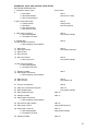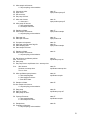
1
USER MANUAL FOR THE pCO2 SYSTEM
SOFTWARE VERSION 03.18
Manual rev date 8/8/2010
The gashound pCO2 system uses an LI820 model CO2 analyzer as the heart of a small low
powered system for long term monitoring of sea surface and atmospheric CO2 on moored ocean
buoys. The system uses a PMEL designed and tested equilibrator, and also a PMEL designed
controller and data logger. It also uses the Iridium satellite system to transmit real-time data, and
has a GPS module for accurate date and time.
1. USER COMMANDS
All user commands except those specifically designated as “hotkey” commands are entered when
the system is in monitor mode. Only hotkey commands are available when the system is in log
mode. The user commands may be entered in either uppercase or lowercase. The _ character
in the command strings is used to denote a space character. All following command strings are
assumed to be terminated with the ENTER key. The symbol <> will be short hand for the enter
key. Spaces MUST be included as shown.
1.1 SYSTEM CONFIGURATION AND STATUS COMMAND.
status<>
shows current system configuration settings.
st<>
same as status command.
config<>
auto configuration command
co<>
same as config.
1.2. SYSTEM STATUS.
The system status screen has been rearranged and is shown below. Bold is entered by the user,
normal type is the system response.
SYSTEM STATUS
PMEL PCO2 BUOY
Version 03.17.02/17/2010
The current date is
The current time is
The current platform is
The current Location is
The current project is
GPS time setting is
GPS set time is
GPS fix interval is
Logic battery is
Iridium battery is
Flash drive is
Disk space used
Data length
Start sector
End sector
Total records
Missed records
03/11/2010
23:38:35
0031
pmel
pco2
active
15:40:35
03:00:00
10.7
10.7
1024 mbytes
000007 Kbytes
000 days
000191
000204
000001
000000
IRIDIUM STATUS
The current card type is
rudics
The PMEL rudics no. is
0088160000519
Reset listening length is
04 hours
PCO2 STATUS
1
Current sample rate is
Fast period length is
Fast sample interval is
Normal sample interval is
Secured length in days is
Normal mode cycles/day
02
10:00:00
00:30:00
03:00:00
01
08
Standard gas concentration is
Standard gas cal press diff is
O2 cal interval is
O2 cal time is
O2 calibration value is
501.01
0.4
01
06:00:00
600
PCO2 CYCLE TIMING
Heater is
off
Current Licor warmup time is
030
Current eqilibrator pump time is
600
Current pump ON time is
030
Current pump off time is
020
Current data sampling time is
030
Current vent delay time is
015
Total cycle length is
19:50
SENSOR INFO
PH is turned
ph sensor type is
ph sensor sn is
Winds is turned
wind type is
wind sn is
compass type is
compass sn is
SSTC is turned
SS sampling is
Number SS samples is
SS sampling is
sst type is
sst sn is
ch0 type is
ch0 sn is
ch1 type is
ch1 sn is
ch2 type is
ch2 sn is
ch3 type is
ch3 sn is
ch4 type is
ch4 sn is
ch5 type is
ch5 sn is
ser ch type is
ser ch sn is
ON
SAMI
1234567890
ON
WINDSONIC
98865
SPARTON
3344221
ON
STARTED
04
STOPPED
SBE16
0123456789
sensor1
1111111111
sensor2
2222222222
sensor3
3333333333
no sensor
no s/n
no sensor
no s/n
no sensor
no s/n
no sensor
no s/n
NOTES:
The data section has added total number of records made, and the number that could not be written to
Flash.
2
If the normal sample interval is greater than or equal to 01:00:00 the status shows cycles per day in the
next line. If the normal interval is less than 01:00:00, the next line will show time between iridium calls,
using 8 cycles per call.
The status of the Licor heater is shown in the first line of the cycle timing section.
The above shows sensor types and serial numbers for ph, winds, and an SBE16 ss sensor. Turning a
data type off will cause those values to no longer appear. Howeve if the SS sensor is turned on and set
to SBE16, all 7 external channels will show.
1.3. AUTO CONFIGURATION ROUTINE
The configuration routine invoked by the config, and co commands automatically leads the user
through all the system configuration parameters. It shows the current value of each parameter
and asks if that is ok. The user has 6 possible 1 character responses to the query as shown by
the bold letters:
yes
this response accepts the current setting and proceeds to the next parameter.
no
this response rejects the current value and prompts the user for a new value. The utility
will then check that the changes made are correct.
back this response goes back one parameter.
done this response accepts all current values and ends the configuration utility.
advance this response advances to the beginning of the next section of the configuration.
return this response returns to the beginning of the previous section.
In the configuration shown below, there are 4 sections, SYSTEM, IRIDIUM, PCO2, AND PCO2
CYCLE TIMING.
1.4. CONFIGURATION ROUTINE SCREENS
The configuration routine queries are shown below, with y answers to each question. Bold is
from the user. Notice there is some information shown in the status screens that cannot be
configured by the user: battery voltages, flash disk size, data stored, cycles per Iridium call, and
total cycle length.
pCO2>co
SYSTEM CONFIG
The current date is
The current time is
The current platform is
The current Location is
The current project is
GPS time setting is
GPS set time is
GPS fix interval is
03/11/2010
23:43:58
0031
pmel
pco2
active
15:40:35
03:00:00
is
is
is
is
is
is
is
is
this
this
this
this
this
this
this
this
ok?
ok?
ok?
ok?
ok?
ok?
ok?
ok?
y
y
y
y
y
y
y
y
IRIDIUM CONFIG
The current card type is
rudics is this ok? y
The PMEL rudics no. is
0088160000519 is this ok? y
Reset listening length is
04 hours is this ok?
PCO2 CONFIG
Current sample rate is
02 is this ok?
Fast period length is
10:00:00 is this ok?
Fast sample interval is
00:30:00 is this ok?
Normal sample interval is
03:00:00 is this ok?
Secured length in days is
01 is this ok?
Standard gas concentration is
501.01 is this ok?
Standard gas cal press diff is
0.4 is this ok?
O2 cal interval is
01 is this ok?
y
y
y
y
y
y
y
y
y
3
O2 cal time is
O2 calibration value is
06:00:00 is this ok?
600 is this ok?
PCO2 CYCLE TIMING
Current Licor warmup time is
030
Current eqilibrator pump time is
600
Current pump ON time is
030
Current pump off time is
020
Current data sampling time is
030
Current vent delay time is
015
Total cycle length is
19:50
SENSOR INFO
PH is turned
ph sensor type is
ph sensor sn is
Winds is turned
wind type is
wind sn is
compass type is
compass sn is
SSTC is turned
Number SS samples is
SS sampling is
sst type is
sst sn is
ch0 type is
ch0 sn is
ch1 type is
ch1 sn is
ch2 type is
ch2 sn is
ch3 type is
ch3 sn is
ch4 type is
ch4 sn is
ch5 type is
ch5 sn is
ser ch type is
ser ch sn is
pCO2>
ON
SAMI
1234567890
ON
WINDSONIC
98865
SPARTON
3344221
ON
04
STOPPED
SBE16
0123456789
sensor1
1111111111
sensor2
2222222222
sensor3
3333333333
no sensor
no s/n
no sensor
no s/n
no sensor
no s/n
no sensor
no s/n
y
y
is
is
is
is
is
is
this
this
this
this
this
this
ok?
ok?
ok?
ok?
ok?
ok?
y
y
y
y
y
y
is
is
is
is
is
is
is
is
is
is
is
is
is
is
is
is
is
is
is
is
is
is
is
is
is
is
is
this
this
this
this
this
this
this
this
this
this
this
this
this
this
this
this
this
this
this
this
this
this
this
this
this
this
this
ok?
ok?
ok?
ok?
ok?
ok?
ok?
ok?
ok?
ok?
ok?
ok?
ok?
ok?
ok?
ok?
ok?
ok?
ok?
ok?
ok?
ok?
ok?
ok?
ok?
ok?
ok?
y
y
y
y
y
y
y
y
y
y
y
y
y
y
y
y
y
y
y
y
y
y
y
y
y
y
y
1.5. INDIVIDUAL CONFIGURATION COMMANDS
Just in case the user wants to enter specific configuration data, the following manual commands
are still valid:
date= mm dd yyyy<>
sets date
time= hh mm ss<>
sets time
project= pppp<>
sets Iridium project name. 4 ascii characters max.
platform= nnnn<>
sets iridium platform number. 4 ascii characters max.
serial= ssssssss<>
sets instrument serial number. 8 ascii characters max.
sample= n<>
sets data sampling interval in hz.
Acceptable entries are 1,2,4 for n.
cardtype= n<>
sets iridium card type.
n is 0 for commercial card, 1 for dod card, 2 for RUDICS
phone= n<>
sets phone number that system will call.
n is 1 to dial the lab, 2 for user entered number, 3 for RUDICS
error= n<>
sets intentional error block in Iridium data.
n must be 0 for deployment.
4
span= ccc.cc<>
spandiff= p.pp<>
interval= hh<>
fastint= hh mm ss<>
gpsint= hh mm ss<>
gpsflag= nn<>
change= hh mm ss<>
equil= sss<>
warmup= sss<>
pumpon= sss<>
pumpoff= sss<>
sampleco2= sss<>
vent= sss<>
heater= n<>
sstc= n<>
o2int= n<>
o2time= hh mm ss<>
sets span gas concentration in ppm. This is a floating point value.
sets span press difference (kpa) for doing span cal. Entry is floating
point. Entering 0 will cause the span cal to always be done.
sets normal mode cycle interval. Hours only.
sets fast mode cycle interval.
sets the gps fix interval
sets the gps time setting suppression flag
sets length of fast sampling mode.
sets length of equilibrator pumping in seconds.
sets length of LI820 warmup before first sample in a cycle.
sets length of pumping during a cycle.
sets length pump off time before sampling during a cycle.
sets length of data sampling during a cycle.
sets length of delay before closing the vent valve.
This value applies to both vents 1 and 2.
sets Licor heater on or off.
n is 0 to turn heater off, 1 to turn heater on
0 disables sstc, 1 enables sstc
n is interval in days between o2 cals.
hh mm ss is the time of day o2 cal will occur.
1.6. INDIVIDUALSTATUS COMMANDS
Just in case the user wants to verify specific configuration status, the following manual
commands are still valid:
version<>
shows software version
date<>
shows current date
time<>
shows current time
batts<>
shows battery voltages.
platform<>
shows platform number
serial<>
shows serial number
project<>
shows project name
sample<>
shows sample interval
cardtype<>
shows iridium card type
phone<>
shoes phone number
error<>
shows error block
span<>
shows span value
spandiff<>
shows span cal difference value.
interval<>
shows interval between cycles in normal period.
fastint<>
shows the fast period cycle interval.
gpsint<>
shows the gps fix interval.
gpsflag<>
shows the gps time setting suppression flag setting.
heater<>
shows Licor heater configuration.
calo2<>
calibrates the O2 sensor in the current environment.
sstc<>
shows current sstc configuration.
o2int<>
shows o2 calibration interval in days.
o2time<>
shows time of day o2 cal is configured to occur.
1.7. COMMANDS TO START LOGGING.
log<>
starts logging with fast period.
fast<>
starts logging with fast period.
normal<>
starts logging in the normal period, bypassing the fast period.
norm<>
starts logging in the normal period, bypassing the fast period.
pos<>
starts the position only mode. This will stay until changed by the user.
poso<>
starts the position only mode.
dep<>
starts the deployment mode. Timeout after a number of days set by user
depl<>
starts the deployment mode.
rec<>
starts recovery mode
5
1.8. DATA COMMANDS
data?<>
read<>
rewind<>
losedata<>
shows amount of data in Flash.
xmodem dumps data
rewinds Flash pointers.
queries to lose Flash data.
1.9. IRIDIUM COMMANDS
iridlog<>
xmit<>
prints Iridium call log.
starts a test Iridium transmission.
1.10. TEST POSITION COMMANDS
apos<>
starts air position test loop
epos<>
starts equilibrator position test loop
rpos<>
starts rest position test loop
spos<>
starts span position test loop
zpos<>
starts zero position test loop
nopos<>
starts the test loop without changing any valves.
While in any of these positions, the following hotkey commands are all live ( no <> is necessary:
a
e
s
z
p
h
l
^z
^s
1
2
changes to the air position.
changes to the equilibrator position.
changes to the span position.
changesto the zero position.
Toggles the pump on or off.
Toggles the heater on or off.
(lower case L) Toggles the licor power on and off.
( control-z) starts the zero calibration sequence.
(control-s) starts the span calibration sequence.
(one) cycles vent number 1.
cycles vent number 2.
1.11 ASSEMBLY AND TESTING COMMANDS
pwr1on<>
turns on 12 volt regulator.
Must be on for pump or valves to work.
pwr1off<>
turns of 12 volt regulator
pwr2on<>
turns on 15 volt regulator.
Must be on for licor to work.
pwr2off<>
turns off 15 volt regulator
anapwron<>
turns on analog power on CO2 board
anapwroff<>
turns off analog power.
pumpon<>
switches on pump power.
pumpoff<>
switches off pump power
licoron<>
switches on licor
licoroff<>
switches off licor
licorcfg<>
does a licor configuration sequence.
iridpwron<>
turns on Iridium power
iridpwroff<>
turns off Iridium power
valves= x x x x x x<>
sets valves to the sequence entered, x can be o (letter o) or b.
valve n x
sets valve n to x side where x is o or b.
gps<>
gets GPS fix and sets system clock.
xmit<>
starts a test Iridium transmission.
testsstc
starts sampling the SS sensor.
Ssgetconfig
gets configuration of attached ss sensor
1.12. MISC COMMANDS
tasks?<>
resets<>
missed<>
shows task information in operating system.
shows log of resets
shows count of missed flash writes
6
1.13. DETAILS OF TEST COMMANDS
GPS COMMAND.
When the gps command is entered from the monitor mode, it immediately starts the gps
acquisition routines. The RF tube must be exposed to the sky for the GPS fix to be successful. If
successful, the software sets the time and date in the CO2 system. If not successful, the GPS
software will time out after 3 5-minute attempts. If this occurs, then the GPS should be repaired,
the cable checked, or the RF tube replaced.
XMIT COMMAND.
The xmit command attempts to make a call to the Lab using the Iridium modem. If a log period
has been interrupted, and there is data in the Iridium buffer, the system will send that data back to
the lab. If there is no data in the Iridium buffer, the system will create a test buffer, and send that
instead. Again, the RF tube must be exposed to the sky. If the call is not successful, the system
should be fixed.
TESTSSTC COMMAND.
The testsstc command causes the system to continuously request data from the SBE37, every 5
to 6 seconds. It can be stopped by a ^C.
“HOT KEY” COMMANDS USED DURING LOGGING
When in a logging mode, several commands are available to check on the system status. All
these commands are initiated by pessing any key on the keyboard. The system will type the
message “enter command within 10 seconds”. Any of the following commands can then be
entered. These are one key commands and none of them require the enter key.
^C
c
f
i
m
r
t
s
control-C causes the system to exit logging and return to the monitor mode.l
prints the iridium call log.
prints the Iridium fast buffer.
prints the Iridium buffer.
prints count of missed flash writes.
prints log of resets.
shows task list currently in the scheduler.
shows system status screen.
2. LOG(FAST) AND NORMAL(NORM) MODE DESCRIPTION
The log and normal commands force the co2 system to go into its data logging modes.
The log command starts the system at the beginning of its fast sampling period. The fast period
starts at the time the log command is entered, and extends for as long as the time configured into
the system’s fast mode length variable. It will start the first sampling cycle 5 seconds after entry
of the command. For example if the cycles take 15 minutes to complete; the system is
configured for a 1 hour fast interval, and a 6 hour fast mode length; and the system is turned on
at 13:30:00, the system will behave in the following way:
13:30:00
log command entered;
13:30:05,
the first cycle of data will start;
13:45:05
the first cycle will end;
14:30:05
the second cycle will start;
14:45:05
the second cycle ends;
15:30:05
the third cycle starts;
15:45:05
the third cycle ends;
16:30:05
the fourth cycle starts;
16:45:05
the fourth cycle ends;
17:30:05
the fifth cycle starts;
17:45:05
the fifth cycle ends;
th
18:30:05
the 6 cycle starts;
th
18:45:05
the 6 cycle ends;
19:30:00
change to normal mode
7
Notice that the change to normal mode is the start time + the fast mode length. Any data samples
that occur within those limits will be recorded.
The system keeps its Iridium transmitter awake for incoming calls from hh:00 to hh:59, where hh
is any hour that occurs during the fast mode period.
At the change to normal mode, the system will call the lab and send all data sampled during the
fast period.
In the normal sampling mode, the cycles occur on clock times, with the first possible sample time
assumed to be at 00:00:00. For instance if the normal mode interval is 3 hours, the samples
times will be 00:00:00, 03:00:00, 06:00:00, 09:00:00, etc up to 21:00:00. Upon entering into
normal mode, the system will take the next cycle on time, and that will be the first sample of the
first day’s worth of data. In the above example, system into normal mode occurs at 19:30:00.
The next sample after 19:30:00 is 21:00:00, so that becomes the first sample in the day’s data.
The last sample in the day’s data will start at 18:00:00 ( the next julian day), and end at 18:15:00.
After this cycle ends, the system will send this day’s data to the lab.
In the normal period, the system does not make its Iridium transmitter available for incoming calls.
2.1. LOG AND NORMAL STARTUP
2.1.1. KEYBOARD COMMANDS
When the log or normal command is entered from the keyboard, the system forces the user to
okay or set 4 of the parameters that are available in the config routines. These are as shown:
The current date is
01/01/2003 is this ok? y
The current time is
01:03:10 is this ok? y
Span concentration is
351.0 is this ok? y
O2 calibration value is
607 is this ok?
Answering no to any of these questions will allow the user to set the values.
Next, the system shows the entire status screen and asks if it is okay. Answering yes continues
on, answering no exits out to the pco2> prompt to allow the user to correct the configuration.
Last, if the file on the flash has any data in it, the system allows the user to keep or discard that
data. Answering y will LOSE the data, answering n will KEEP the data, and answering ^C will
jump out to the pco2> prompt.
In the case of the O2 calibration, answering n to the question will cause the system to recalibrate
the sensor. This should be done at a time when the air is reasonably fresh. The Oxygen
calibration cycle takes two minutes and 20 seconds. The system is pumped for two minutes to
get fresh air into the o2 sensor. After pumping, the system is allowed to stabilize for 15 seconds,
then the o2 calibration value is acquired.
The only way to access these questions is through the keyboard commands.
2.1.2. POWER UP RESET
When the power supply or battery pack is connected to the system, if the terminal cable is
connected to a computer, the system will go to the system prompt and wait for user input. If the
terminal cable is not connected, it will go to normal mode operation, with an Iridium window
opened and listening for an incoming call. The length of this window is set in the system
configuration. After this window times out, it reverts to the normal mode window settings.
2.1.2. WATCHDOG OR RESET BUTTTON RESET
When the watchdog times out, or the reset button is pressed, the system goes straight to normal
mode, regardless of whether or not the terminal is connected.
2.2. POS, REC AND DEP MODES.
8
The pos, and dep modes are specialized modes for use during the deployment period. Neither of
these modes logs the normal data set, and they are both for use only in specialized
circumstances. The rec (recovery) mode is used to track the system at recovery time.
POS MODE
The pos mode is used to conserve power if necessary during a deployment. The system will not
run the Licor, valves, or pump, or gather oxygen or rh data. It will continue to acquire GPS data
and send it back in the regular data format, and it will also continue to listen for incoming Iridium
calls at its regularly scheduled times. The system will stay in this mode until the user calls and
forces it into another.
DEP MODE
The dep mode is intended for use during the actual deployment from the ship to minimize the
possibility of getting water into the equilibrator when the system is being dragged behind the ship.
In this mode, the same data is acquired as during the pos mode. In addition, the valves are in
rest mode with the equilibrator vent closed to prevent water from being forced into the
equilibrator. The Iridium is listening 10 minutes on every half hour during this mode, and it will
timeout after a user determined number of days, shown in the st screens as “secured length in
days” at which time it will go into normal mode. The user may call after the danger period is past
and set the system into the normal data gathering modes.
The number of days this mode lasts is set during the configuration process, or can also be set in
a dial up command.
REC MODE
Recovery mode has been added in version 03.17. When this mode is commanded, the system
restarts, immediately takes a GPS time and position, and sends it back to the lab. The interval for
this will default to 1 hour, unless another value is sent to the system as part of the Iridium
command string. The system will watch for incoming Iridium calls at the standard 2330 to 2340
every day. The data header will be RECV.
2.2.1. IRIDIUM LISTENING WINDOWS
The system listens for incoming calls during the various modes. These times are:
FAST MODE the system listens from hh:20 to hh:30 and hh:50 to hh:60.
NORMAL MODE listens 22:30 to 22:36 every day.
POSO mode listens 22:30 to 22:36 every day.
DEP mode listens hh:00 to hhh:10 and hh:20 to hh:40.
RECovery mode listens 22:30 to 22:36 every day.
2.3. GPS DATA AND ACQUISITION TIMES AND SETTING THE SYSTEM CLOCK.
GPS data is now included in the second line of each cycle of CO2 data. There are two portions of
the GPS data line. The first portion of the GPS line contains a date, time, lat and long, the time to
acquire the fix in seconds, and a fix quality value. All this is used for buoy tracking. The date and
time is when the position information is valid, and has nothing to do with the CO2 data. The last
half of the GPS line contains two date and time values associated with using the GPS time to set
the system clock.
The GPS interval used for acquiring the tracking data is an item that must be entered in the
configuration, and will show up in the status screens.
The time of day to use the GPS to set the system time also must be set by the user.
See section 2.3.2 for a full explanation of using the GPS fixes to control the system clock.
2.3.1. TRACKING BUOY POSITION IN THE GPS LINE.
9
Using the time and lat/long values in the first half of the GPS line the buoy position can be
monitored for tracking and recovery purposes. The GPS information is set to all zeroes for its
initialization value. It will be updated when the GPS acquires a new position fix. If no GPS
information is acquired, the previous fix value, or the initialization values, will remain in the buffer.
In FAST mode, the GPS will start acquiring data 2 minutes after the system is started. Updates
will occur at the fast cycle interval, so each cycle should have an updated GPS position fix.
When the system changes over to NORMAL, POS, or DEP mode, the GPS times are calculated
to be 5 minutes prior to the start of the next co2 cycle. The fix is updated at the time interval
entered by the user.
In recovery mode, the system begins acquiring GPS position information 10 seconds after
entering the mode. As soon as the position is acquired, it is sent to the lab. This occurs at a
default interval of one hour. This interval can be hcanged by the user with an Iridium command.
If the GPS does not acquire data, the GPS line will retain the fix information from the most recent
successful fix acquisition.
2.3.2. USING THE GPS TO SET SYSTEM TIME
The GPS unit is used to check and if necessary set the system date and time automatically. This
feature can be turned off using the GPS time setting switch in the configuration screens only for
purposes of bench testing. If set to active, the GPs time setting will occur; if set to inactive it will
not occur.
This utility does not preclude the user from setting the time manually if desired prior to
deployment. If the time is set accurately to GPS time, then the software will not do anything until
the system time has changed enough to require adjustment. However, if the user accidentally
sets the time incorrectly, this utility will correct that error and then maintain the correct time during
the remainder of the deployment. It also allows the user to deploy a system without setting the
time at all, as the utility will automatically set the time correctly.
Three GPS fixes are used to determine the accuracy of the system clock and take appropriate
action. If the time is accurate already, a successful time check will result in not changes. The
main cause of an unsuccessful time check is inability to acquire GPS fixes.
The time check will not occur if a CO2 sampling cycle is in progress, but will be delayed until after
the cycle.
The user must configure a time of day for the “GPS set time” value that will be when the time
correction will occur during normal operation. The GPS time difference acquisition is forced to
occur 5 minutes before that time. The time should be near 1200, and should be at a time when
nothing is scheduled. Since the CO2 cycles typically last 20 minutes, a time of 12:35:00 would be
appropriate.
2.3.2.1. FAST MODE
In fast mode, the unit starts acquiring the three fixes 5 minutes after the mode starts, and the first
attempt to check the clock is 10 minutes after starting the system. If the time is successfully
checked, there are no more attempts during the remainder of the fast period. If the time is
unsuccessfully checked, the system attempts on an hourly schedule until either success, or the
end of the fast period.
2.3.2.2. NORMAL, DEP, AND POSITION ONLY MODES.
In the other three modes (normal, pos, dep), the unit starts acquiring the GPS fixes immediately
upon entering that mode, and the first attempt to check the clock is 3 minutes after entering that
mode. If the time is successfully checked, the checking interval is changed to once a day. If the
check is unsuccessful, the interval remains at 1 hour until 24 hourly checks have been made. If a
successful check is not made in this time, then the time checking is disabled to save power.
10
2.3.2.4. ACQUIRING TIME DIFFERENCE
For each of the three fixes the difference between the system clock and the GPS date and time is
calculated. These differences are compared to each other, and one of the fixes is selected as
correct. This difference is then used by another task to actually set the date and time. This
occurs as per the description above in sections 2.3.2.1 and 2.3.2.2.
2.3.2.5. CHECKING THE TIME
A successful time check consists of using the time from one of the three fixes as discussed
above, comparing that time to the system time and taking action according to the three possible
outcomes:
1. If the difference is less than 5 seconds, nothing happens.
2. If the difference is greater than or equal to 5 seconds and less than or equal to 60 seconds,
the time is adjusted by the difference amount.
3. If the difference is greater than 60 seconds, the GPS date and time are jammed into the
system clock. In this case the software is restarted in order to force the tasker and scheduler to
adjust to the new time. The unit will restart into the same mode it was in before the time set event;
fast, normal, dep, or pos. In fast, and dep modes, the jam time will also be the new start time of
that mode.
The daily time setting during normal mode must occur at a time when nothing is happening. A
time during the 12:00 hour is suggested, to avoid having an adjustment cause the date to change.
2.3.2.6. INFORMATION IN THE IRIDIUM DATA
Every time a time check event occurs, and has been successful according to one of the three
possible outcomes, the system time before and after the event are displayed in the GPS line of
every scan until the next time setting event. These times will show as zeroes prior to the first time
set attempt.
2.3.2.7. SUPRESSING TIME SETTING
A GPS time setting suppression flag is available to avoid setting the clock during lag testing. This
flag will remain in effect as long as the system power remains on, or the user resets it. A power
up cycle will automatically default the flag to allow the GPS time setting to occur. This flag can be
accessed using the co command. It can also be set or cleared directly using the setflag= nn <>
command. It can be checked using the setflag<> command.
2.4. DATA ACQUISITION DETAILS.
When the data is sampled, it must pass several limit tests before it is accepted as valid.
LICOR DATA
FLASH VALUES
For flash storage values the ranges are established to keep the data within the formatted text
space allowed, but allow all values within that range to be recorded.
CO2 must be greater than -99999, and smaller than 999999.
Temp must be greater than -99999, and smaller than 999999.
Pressure must be greater than -99999, and smaller than 999999.
In these three values, numbers smaller than -99999 are limited to that value, and numbers larger
than 999999 are limited to that value.
Raw1 must be greater than 1000000 and smaller than 10000000, or it is converted to 0.
Raw2 must be greater than 1000000 and smaller than 10000000, or is it converted to 0.
All flash data is stored in arrays until written.
IRIDIUM AVERAGE VALUES
The Licor must send 5 data values on each sample. If there are not 5 values to be found, then
that sample is tossed out. On that line in the capture file, only the O2, Rh, and Rh Temps are
printed.
If 5 Licor values are received, the data is used in the statistics. For creating the averages and
standard deviations used in the Iridium transmissions the ranges are limited as follows:
11
Licor temp must be greater than -5.00 and less than + 50.00 degrees.
Licor pressure must be greater than 20 kpa and less than 200 kpa.
Licor CO2 must be greater than -50.00 and less than + 1000.00 ppm.
Licor raw values must be greater than 1000000 and less than 10000000.
If any of these values fall out of limit, then the entire sample is invalid, and will not be used in the
statistical calculations. However, these 5 values are printed on the display.
Rh from 0.00 to 110.00 %.
Rh temp from -40.00 to + 40.00 degrees.
There are currently no limits on the Oxygen values, or the SSTC values.
The five Licor parameters, oxygen, relative humidity, and relative humidity temperature are
sampled in every one of ten different settings or positions. The complete of set of ten position
data plus the GPS, engineering and met data is considered to be one scan of the instrument.
The ten positions are
zero pump on
zero pump on
zero post cal
span pump on
span pump off
span post cal
equilibrator pump on
equilibrator pump off
air pump on
air pump off
2.5. MET DATA.
The met sensors will measure SSTC using a Seabird SBE37SMP, or an SBE16plusv2, and winds using a
C100 compass and a Gill Windsonic sensor. The data for these has been added to the Engineering
header line, except for the SBE16 data which has its own three lines, following the SAMI data.
2.5.1 SSTC DATA and SAMPLING
The SBE16 has been added as an optional SS sensor. The system acquires configuration information
from either the SBE16 or the SBE37, and then averages whatever data the sensor is configured for. As a
result, any configuration of either sensor will be acceptable, as long as the correct output format is
selected. The data must be in engineering units, and ascii text.
The only required configuration for SBE16 is outputformat=3
The only required configuration for SBE37 is outputformat=1
The number of samples for SS data is now settable by the user. Typically for an SBE37 the number of
samples should be set to 10, and it takes about 5 seconds between samples. For the SBE16, the
number of samples is unknown at this time.
Any time the configuration of the SS sensor is changed, the testsstc command must be used to make
sure the system interprets the data correctly.
Also, as of version 0318, there is a SS sampling flag that will start or stop SS sampling. If the flag says
STOPPED, it will not sample the SS sensor; if the flag says STARTED, it will. This feature will allow the
user to protect the SS sensors by not sampling until the system is in the water. The testsstc command
and the DEP deployment mode will turn the SS sampling flag off. No other modes will change the flag.
The Iridium dial up command TL will turn on the flag, and schedule a startnow command at the next
12
normal sample interval time. The iridium dialup command SS will stop the SS sensor and turn off the
flag.
This feature envisions the following scenario:
1. The user will put the SS instrument into startlater logging mode manually, choosing a
date safely in the future to assure no logging will take place on deck.
2. The instrument is connected to the mapco2 system.
a. The user applies power to the MAPCO2 system – upon powering up, the SSTC
sampling flag is set to off.
3. The user will use the testsstc command to acquire the SS instrument configuration. It will
only sample 2 times.
4. When the user exits the testsstc mode, the instrument is still in startlater mode, and the
sampling flag is unchanged.
5. The mapco2 system may be tested or run leading up to deployment, however SS data
will depend on the state of the flag; for deployments the flag is off due to power up; in the
lab it may be on for testing.
6. The system is deployed in dep mode (In theory the flag will be off because it should
already be off – but the MAPCO2 firmware should just leave it as it is. If for some
reason it is on – that will be okay since the system does not actually sample in the
deployment mode).
7. The system is sent the RF iridium command.
8. The system is sent the TL iridium command. The TL command will always stop, then
start the SS instrument at the next correct normal sampling interval time; i.e. 0000, 0300,
0600, etc. The flag is set to sampling (immediately upon receiving the TL command),
and data can be acquired for fast mode testing.
9. The system can be sent the SS iridium command at any time to stop the sampling before
recovery.
10. Changing the sampling flag state only occurs in the testsstc code, during system
configuration, and in the dial up commands.
11. There will be no automatic flag changes when any of the modes begin.
The SSTC data sampling is started at the beginning of the equilibrator pump on period. After the number
of samples required is taken, all data will have averages and standard deviations calculated.
If an SBE37 is attached, the T,C and S data will be placed into the engineering line of the Iridium data. In
addition, the 10 samples will be stored in the flash data.
If an SBE16 is attached, the T, C, and S spaces in the engineering header line will be zeroed, and all
SBE16 data will be placed into three lines following either the main data body, or after the SAMI data. All
raw values are stored into Flash. See section 9 for a description of the SBE16 data lines.
sstc= n<> will enable or disable the SSTC, where n = 0 disables it, and n = 1 enables it. The command
sstc<> checks the current status of the SSTC. There is also a test command testsstc<> that allows the
user to sample the T and C in a continuous loop for testing purposes, similar to the test loops for the
Licor. The Iridium data stream will have the data set to zeroes if the SSTC is disabled, and also if it is not
communicating. In the Flash data, if the SSTC is disabled or not communicating the number of samples
will be stated as being zero.
This will work exactly the same during fast and normal modes.
The extra power required for this is minimal, since the SBE37 has its own power. The system must talk to
it every cycle and deal with the data, so it will probably take less than a milliamp average.
2.5.2. WIND DATA.
13
The wind data is sampled continuously during the data cycle at a 1 hertz rate. At the end of the
sampling, the data is calculated as vectors
2.6. OXYGEN CALIBRATION INTERFACE.
The oxygen sensor will be automatically calibrated during the NORMAL deployment period. The
user must enter an o2 calibration interval in days, and the time of day that the calibration should
occur. When the configured interval has passed and the cycle at the correct time of day occurs,
the calibration takes place at the end of the air pump off data sampling in that cycle.
Note that the time of day is entered as a zulu time. If the calibration time is desired to be a
specific local time, the user is responsible for converting the desired local time into a zulu value.
Also, even though the time of day is entered as hh mm ss, only the hour value is used to
determine which cycle is the correct one. Also, it is incumbent upon the user to make sure that
the time of day set into the o2 calibration configuration corresponds to the time that a cycle will
occur. Obviously, the recalibrations wont occur if the time is set for say 09:00:00, but the interval
is 4 hours, and the cycles occur at 08:00:00 and 12:00:00.
If the system is in normal mode, and the normal cycle interval is 1 hour or greater, then the o2
calibration will perform as outlined above.
If the system is in normal mode and the cycle interval is less than 1 hour, the calibration interval is
in cycles instead of days. This is to facilitate the debugging process.
If the system is in fast mode, the o2 calibration software is disabled.
2.7. MISSED DATA WRITES TO FLASH.
It is possible that the compact flash will be unable to store data. If this occurs, the system will try
three times to write the data to flash. during each of these tries, it will try turn the flash off, wait 20
milliseconds, and attempt to turn it back on three times. If turning it on fails three times in a row,
the data will be lost and the count of flash power up failures will be incremented. If the power up
cycles work okay, but the flash is still unable to write the data after three tries, then the count of
flash write failures will be incremented. In the logging modes, when the count of cycles is shown,
the total count of missed flash writes ( the sum of missed power-ons and missed writes) is also
now shown. In addition, the individual counters can be shown either by using the hot-key m
command during logging, or by using the missing<> command at the pco2> prompt.
3.
CALIBRATION CYCLES AND ERROR FLAGS
The system utilizes the LI820’s zero calibration and span calibration commands to self calibrate
during every cycle. There are 5 flags for the zero calibration and 5 for the span calibration that
show the status. These flags are shown in hexadecimal form in the 16 bit flag value in the
engineering header line, where the two most significant hex characters are used to show the
span calibration flags, and the two least significant are used to show the zero calibration flags.
The instrument sends the zero or span calibration command to the Licor, then starts a timer to
prevent the system from freezing up if the procedure doesn’t complete. The zero calibration
command is always done. The span calibration is only done if there is a minimum difference
between the span pumol on pressure and the span pump off pressure. The required difference is
a configuration value entered by the user. Entering zero will cause the span calibration to always
be done.
The Licor response is as follows:
1. It either ACKS the command i it understands it, or NAKS if it doesn’t understand it.
2. IF it AKCS the command, it begins the calibration process. After approximately a minute, it
returns a message that contains new zero and span calibration coefficients. it returns both
coefficients after both the span and zero cals.
3. If anything goes wrong during theis process the Licor might send an error message to the
instrument.
14
The bits in the 16 bit flag word have binary weightings of 2^15 for the ms bit, and 2^0 for the least
significant bit. A list of binary weighting versus meaning is listed as follows. The list from top to
bottom shows the flag word bits as seen from left to right:
WEIGHT
MEANING
2^15
2^14
2^13
2^12
2^11
2^10
2^9
2^8
2^7
2^6
2^5
2^4
2^3
2^2
2^1
2^0
not used
not used
not used
span flag 5
span flag 4
span flag 3
span flag 2
span flag 1
not used
not used
not used
zero flag 5
zero flag 4
zero flag 3
zero flag 2
zero flag 1
FLAG WORD VALUE
(1000 hex)
(0800 hex)
(0400 hex)
(0200 hex)
(0100 hex)
(0010 hex)
(0008 hex)
(0004 hex)
(0002 hex)
(0001 hex)
3.1. FLAG MEANINGS
During the span calibration procedure:
span flag 1 is set if the Licor is set if the calibration attempt times out before completion.
span flag 2 is set if the Licor returns a NAK in response to the cal command.
span flag 3 is set it the Licor sends an error message any time during the calibration procedure.
span flag 4 is set if the new zero cal coefficient is not found in the response from the Licor.
span flag 5 is set if the new span calibration coefficient is not found in the response from the
Licor.
FF in the span flags indicates that the span calibration was skipped due to lack of gas. See
section 3.2.
During the zero calibration procedure:
zero flag 1 is set if the Licor is set if the calibration attempt times out before completion.
zero flag 2 is set if the Licor returns a NAK in response to the cal command.
zero flag 3 is set it the Licor sends an error message any time during the calibration procedure.
zero flag 4 is set if the new zero cal coefficient is not found in the response from the Licor.
zero flag 5 is set if the new span calibration coefficient is not found in the response from the Licor.
Since there are 5 flags for span, and also for zero, there are 32 possible combinations for each
calibration process. If all flags are zero, that indicates a good calibration.
3.2. SPAN CALIBRATION INFORMATION
The span calibration cycle is somewhat different from the others in that its pressure is always
higher than atmospheric, and so instead of turning the pump on and then off, the span cycle
merely opens the valve to the span cylinder and allows the gas to flow during the “pump on” time,
then turns off the valve during the “pump off” time. Precautions must be taken to prevent
calibration cycles if the span bottle runs out of gas. The user can set into the system a minimum
pressure differential which the (valve open pressure – valve closed pressure) must exceed before
the span calibration will take place. In this way if the span bottle runs out of gas, the calibration
will be skipped, and the last valid span coefficient will be used. If the calibration is skipped due to
no span gas, the span bits in the flag word will be set to FF. If the user wants to force span
calibrations to always occur, the span differential value should be set to 0.00.
15
4. DIAL UP COMMANDS
Version 03.05 and higher have available several dial up commands to control the actions of the
system from the lab. All these command require a system in the lab to dial the system and
interact with it. This could either be the lab system, or a laptop. If using a laptop, a copy of
CO2_Dialup_xx.exe must be installed and operation on the laptop, where xx is the latest version
number of the software.
4.1. COMMAND SYNOPSIS.
In the following command list, the word now implies sending data to the computer that is currently
connected, rather than the lab system.
TWO-BYTE CODE
SF
RD
RF
RN
PO
CI hh
CS nnn.nn
FX
ST
WR
DESCRIPTION
Send all data to connected system.
Reboot into deployment mode. No delay
Reboot into fast mode. Waits 10 minutes.
Reboot into normal mode. No delay.
Reboot into position only mode. No delay.
Change normal mode sampling interval. Expects integer.
Change span value. Expects floating point value.
force xmit of all Iridium data. Hangs up and calls the lab system.
Send test data to system connected.
restore normal listening window.
New in version 03.17
SD
Send status info in call.
SS
Stop SS sensor. Acks with result.
TN
Start SS sensor now. Acks with result.
RR
Reboot into Recovery mode. No delay.
TL
Start SS sensor at start of next hour. Acks with start time.
LO nnnnnnnnnn
New location
GI hh mm ss
New Gps interval
LL hh
New listen length
FL hh mm ss New fast length
FI hh mm ss New Fast interval
SE dd
New secured length
OI dd
New o2 cal int
EQ sss
New equilibrator time
4.2. COMMAND DETAILS
The following commands will send any Iridium data first, then change mode:
PO reboot to Position Only mode.
RD reboot to Deployment mode.
RF reboot to fast mode. This command also acquires the SS sensor configuration.
RN reboot to normal mode.
RR reboot to recovery mode.
5. LICOR CONFIGURATION.
The system actively sets several of the Licor parameters. Any that are not discussed below are
left at their default settings.
The li820 is configured as follows:
1. <Rs232><CO2>
TRUE
2. <Rs232><Cellt>
TRUE
3. <Rs232><Cellp>
TRUE
4. <Rs232><CO2abs> FALSE
// this puts co2 data in the output stream.
// this puts cell temperature in the output stream.
// this puts the cell pressure in the output stream.
// this takes the CO2 absorption out of the output stream.
16
5. <Rs232><Ivolt>
6. <Rs232><Raw>
7. <Rs232><strip>
8. <Rs232><echo>
9. <cfg><outrate>
10. <cfg.><filter>
11. <cfg><heater>
12. <cfg><pcomp>
13. <cfg><almena>
14. <cfg><bench>
15. <cfg><span>
False
TRUE
TRUE
FALSE
0
0
XXXX
TRUE
FALSE
14
1000
// this takes the data out of the output stream.
// this puts the raw sensor data in the output stream.
// this strips the XML text from the data output stream.
// this turns off local echo
// system must poll for data.
// this turns off internal filtering.
// this turns heater on of off according to the user configuration.
// pressure compensates co2 data.
// turns off alarm enable.
// selects 14 cm optical bench length.
// sets 1000 ppm span.
6. IRIDIUM MONITOR AND GPS SCHEDULES IN THE DIFFERENT MODES
6.1. IRIDIUM MONITOR TIMES This is when the modem is watching for incoming calls.
6.1.1. Fast mode. The iridium monitor is on from hh:20 to hh:30 and hh:50 to (hh_+1):00. Ten minutes
out of every half hour.
6.1.2. Normal mode. The Iridium monitor is on from 22:30 to 22:36 Zulu every day.
6.1.3. Position only mode. This is same as normal mode.
6.6.4. Deployment mode. The iridium monitor is on from hh:00 to hh:10 and hh:30 to hh:40 every
hour.
6.6.5. Recovery mode. The Iridium monitor is on from 22:30 to 22:36 Zulu every day.
6.2. GPS POSITION ACQUISITION. This is when the system acquires the fix used for position tracking.
It should be noted that there is only one update interval for every mode.
6.2.1. Fast mode. GPS position is acquired 10 seconds after starting. The update interval is the same
as the fast sample interval.
6.2.2. Normal mode. GPS is acquired 5 minutes before the next data cycle. The update interval is set
by the user.
6.2.3. Deployment mode. Same as normal mode.
6.2.4. Position only mode. Same as normal mode.
6.3. GPS TIME SETTING. This is when the GPS is used to set the system time. This function is never
allowed to occur when a data cycle is in progress.
6.3.1. Fast mode. The data acquisition starts 5 minutes after mode entry. The time setting occurs 10
minutes after mode entry. This repeats hourly until a successful time setting event, or 24 attempts. In
either case, this is then disabled for the remainder of fast mode.
6.3.2. Normal mode. Data acquisition begins 1 second after mode entry. Time set occurs 3 minutes
later. This occurs hourly until either a successful time setting event, or 24 attempts. If the time setting is
successful, this utility occurs daily at the time entered by the user. If unsuccessful, it is disabled.
6.3.3. Deployment mode. Same as normal mode.
6.3.4. Position only mode. Same as normal mode.
7. ACQUIRING PH USING A SAMI
SAMIS
The SAMI ph sensor has been interfaced with the CO2 system to add real-time ph data to the Iridium
transmissions. This capability can be turned on or off in the configuration procedure, the same as winds
or SSTC. There are two varieties of SAMIs, SAMI and SAMI2. When configuring the ph sensor
information, the string SAMI1 OR SAMI2 MUST BE ENTERED.
IN this version, only sami2 data has been verified to work.
SAMI1
17
The data stream from the SAMI1 is 16 lines of text, which are appended to the CO2 data, along with a
system time stamp. For details on preparing a SAMI for deployment, see the SAMI user manual. There
are a couple SAMI1 idiosyncrasies which are critical to proper operation of the COMBINED system; first,
there is no polled mode, it sends serial data as it is sampling. Second, the only configuration information
it accepts is date; time; and sample interval. The time should be Zulu, and the interval should be 180
(minutes). When the enter key is pressed to send it the desired sampling interval, the first sample is
started immediately, the next sample will be one sampling interval later, etc. Sami1s will always sample
their data approximately 2 minutes into the CO2 cycles.
SAMI2
The data from the SAMI2 will show up as 6 lines of text, plus a time header, in the same position as the
SAMI1 data. The new SAMI2s come with a Windows app that simplifies the process of starting the
instrument. The start time can be set to any 5 minute interval clock time. If the CO2 cycle is the standard
19:30 long, the SAMI2 can be started at 15 minutes after the start of a CO2 cycle, and the data will be
sampled just after the equilibrator pump turns off.
In version 03.17 and higher, the fast mode is synced to start on the half-hour, rather than immediately in
order to sync the system and SAMI as closely as possible. If the fast interval is the usual 30 minutes, then
5 FAST samples will show zero filled SAMI data, and 1, the cycle on the 3 hour interval, will show real
SAMI data.
If you want to see the SAMI data on the deck before starting a deployment, it must be at one of the 3 hour
intervals.
During the deployment, if the SAMI clock starts to drift, the watch window will move to accommodate it.
At the start of the deployment, the watch window is the entire CO2 sample cycle period.
Also, during the deployment, if the SAMI data does not appear for 1 week, the system will discontinue
sending zeroed data. It will continue to watch for the SAMI data, and display it if it starts up again.
The SAMI is disabled in DEP and POS modes, and activated in all other modes.
18
8. IRIDIUM DATA FORMAT
data
range
CO2
0-1000 ppm
TEMP
0-100 C
PRES
0-120kpa
RAW1
2.5E6 counts
RAW2
2.5E6 counts
O2
0-100%
RH
0-100%
RH Temp
-10 to 50
SST
-5 to +35
SSC
0 to 7 S/M
resolution
.01 ppm
.01 C
.01kpa
???
???
1%
1%
.1 Deg C
.0001 Deg C
.00001 S/M
The above data will be taken on every cycle, except SST and SSC. The total number of bytes is
around 1100 per cycle.
Taken once each scan will be date, time, calibration flag byte, battery voltages, and two
calibration coefficients. Also taken once per sca
The SSTC will be sampled according to the description in section .
The Iridium data format is shown on the next page. The character _ is used to denote spaces and
CR is used to denote the CR LF end of line. The // plus text following it are comments that will not
be sent. Each character denotes an ascii character, normally decimal digit except in the header
which will be explained. data from each scan will be formatted as shown on the next page.
The data is encoded as follows:
NORM is a data id word denoting data made during the normal period.
FAST is the header word during the fast period.
DEPL is the header during the deployment period.
POSO is the header during the position only period.
RECV is the header during the position only period.
CCKSM is a 16 bit crc checksum value. The checksum calculation starts with the first byte of the
size value.
SIZE is the number of bytes in the data until the start of the next scan, including the size bytes,
but excluding the header bytes or the checksum bytes.. This is also the number of bytes included
in the crc calculation.
YYYY is the year
MO is the month
DD is the date
HH is the hour
MM is the minute
SS is the second
This date and time are when the data scan was started.
RRRRRRRR is an 8 character serial number of the unit. Unused characters are trailing spaces.
PPPP if the 4 character platform number.
The GPS line:
MM/DD/YY is the date that the GPs position fix is valid
HH:MM:SS is the time the position fix is valid
NNNN.NNNN n is the latitude north or south
EEEEE.EEEE e is the longitude ease or west
LLLL is the time to acquire fix is seconds
Q.QQ is a quality factor. Closer to 1 is better.
mm/dd/yyyy hh:mm:ss is the time before a system time check
mm/dd/yyyy hh:mm:ss is the time after a system time check
19
The engineering line:
LB.B is the logic battery.
XB.B is the transmitter battery.
ZEROCOF is the zero coefficient from the licor.
SPANCOF is the span coefficient from the Licor.
FLAG is a flag word with more calibration info in it.
LLLL is the GPS lock time in seconds.
THE Met data is appended to the end of this line:
SS.TMP is sea surface temp average in degrees C with millidegree resolution;
S.SDT is sst standard deviation with millidegree resolution;
C.ONDT is conductivity average in Seimens per meter with 4 decimal places of resolution;
C.NDSD is conductivity standard deviation in Seimens per meter with 4 decimal places of
resolution;
SS.SALS is salinity average 4 decimal places of resolution;
S.SLSD is salinity standard deviation 4 decimal places of resolution;
sUU.U is the signed east-west wind vector in meters per second with .1 m/s resolution;
sVV.V is the signed north-south wind vector in meters per second with .1 m/s resolution;
U.SD is u vector standard deviation in m/s with .01 resolution;
V.SD is v vector standard deviation in m/s with .01 resolution;
RCC is the raw compass value in degrees;
RVV is the raw vane in degrees;
RSS is the raw wind speed in m/s.
The data lines:
MM is the minute after the hour given in the header line when the current line of data was taken.
TE.MP is the licor temp.
T.SDT is the temperature standard deviation.
BPR.ES is the pressure of the licor.
PR.SD is the pressure standard deviation.
PPCO.22 is the pco2 data.
SD.PC is the pco2 standard deviation.
OX.YY is the oxygen reading in percent.
S.O is the standard deviation of the oxygen.
RH is the relative humidity in %.
S.R is the standard deviation of the RH.
RH.T is the temperature from the relative humidity sensor.
S.RT is the standard deviation of the relative humidity temperature.
R1R1R1R1 is the average value for the RAW1 data.
0R!SD is the standard deviuation for the RAW1 data.
R2R2R2R2 is the average for the RAW2 data.
0R2SD is the standard deviation for the RAW2 data.
20
CRNORM_CCKSM_SSIZE_YYYY/MO/DD_HH:MM:SS RRRRRRRR PPPPCR
// 54 char header
MO/DD/YYYY_HH:MM:SS_NNNN.NNNN_n_EEEEE.EEEE_e_LLLL_Q.QQ_mm/dd/yyyy_hh:mm:ss_mm/dd/yyyy_hh:mm:ssCR
// 98 characters GPS line
LB.B_XB.B_Z.EROCOF_S.PANCOF_FLAG_SS.TMP_S.SDT_C.ONDTT_C.NDSD_SS.SALS_S.SLSD_sUU.U_U.SD_sVV.V_V.SD_RCC_RVV_RSSCR
//111
char engr, and met
MM_TE.MP_T.SDT_BPR.ES_PR.SD_PPCO.22_SD.PC_OX.YY_S.O_RH_S.R_RH.T_S.RT R1R1R1R1 0SDR1 R2R2R2R2 0SDR2CR //100 chars zero pump on
MM_TE.MP_T.SDT_BPR.ES_PR.SD_PPCO.22_SD.PC_OX.YY_S.O_RH_S.R_RH.T_S.RT R1R1R1R1 0SDR1 R2R2R2R2 0SDR2CR //100 char zero pump off
MM_TE.MP_T.SDT_BPR.ES_PR.SD_PPCO.22_SD.PC_OX.YY_S.O_RH_S.R_RH.T_S.RT R1R1R1R1 0SDR1 R2R2R2R2 0SDR2CR //100 char zero post cal
MM_TE.MP_T.SDT_BPR.ES_PR.SD_PPCO.22_SD.PC_OX.YY_S.O_RH_S.R_RH.T_S.RT R1R1R1R1 0SDR1 R2R2R2R2 0SDR2CR //100 char span pump on
MM_TE.MP_T.SDT_BPR.ES_PR.SD_PPCO.22_SD.PC_OX.YY_S.O_RH_S.R_RH.T_S.RT R1R1R1R1 0SDR1 R2R2R2R2 0SDR2CR //100 char span pump off
MM_TE.MP_T.SDT_BPR.ES_PR.SD_PPCO.22_SD.PC_OX.YY_S.O_RH_S.R_RH.T_S.RT R1R1R1R1 0SDR1 R2R2R2R2 0SDR2CR //100 char span post cal
MM_TE.MP_T.SDT_BPR.ES_PR.SD_PPCO.22_SD.PC_OX.YY_S.O_RH_S.R_RH.T_S.RT R1R1R1R1 0SDR1 R2R2R2R2 0SDR2CR //100 char equil pump on
MM_TE.MP_T.SDT_BPR.ES_PR.SD_PPCO.22_SD.PC_OX.YY_S.O_RH_S.R_RH.T_S.RT R1R1R1R1 0SDR1 R2R2R2R2 0SDR2CR //100 char equil pump off
MM_TE.MP_T.SDT_BPR.ES_PR.SD_PPCO.22_SD.PC_OX.YY_S.O_RH_S.R_RH.T_S.RT R1R1R1R1 0SDR1 R2R2R2R2 0SDR2CR //100 char air pump on
MM_TE.MP_T.SDT_BPR.ES_PR.SD_PPCO.22_SD.PC_OX.YY_S.O_RH_S.R_RH.T_S.RT R1R1R1R1 0SDR1 R2R2R2R2 0SDR2CR //100 char air pump off
SW_xCO2(dry) 0000.00 Atm_xCO2(dry) 0000.00
SBE16 DATA
tt.tttt tt.tttt cc.ccccc cc.ccccc pppp.pp pppp.pp v.vvvv v.vvvv v.vvvv v.vvvv v.vvvv v.vvvv v.vvvv v.vvvv v.vvvv v.vvvv v.vvvv v.vvvv
tt.tttt tt.tttt pppp.ppppp pppp.ppppp ttt.tttt tt.tttt pppp.ppppp pp.pp oooo.ooo oooo.ooo
sss.ssss sss.ssss vvvv.vvv vvvv.vvv ddd.dddd ddd.dddd ee.e iii.i
END SBE16
21
9. ADDING THE SBE16 AS AN OPTIONA SENSOR.
The SBE16 can be used in place of the SBE37 for ss data. The SBE16 allows up to 6 analog and 1 serial
auxiliary sensors. Because this can potentially be a large amount of data, it is appended in three lines
following the SAMI data in the Iridium buffer.
9.1. SBE16 DATA IN IRIDIUM BUFFER
The SBE16 data is three extra lines added at the end of the data, after the SAMI data if it is in the
system. If the SBE16 is selected, the T,C, and S data in the header line is zeroed out.
The format of the SBE16 data is as shown on the previous page (pg.24):
t is temperature;
c is conductivity;
p is pressure;
v is voltage, auxiliary chans 0 through 5;
Line 2 is serial channel data:
t is temperature;
p is pressure;
o is oxygen;
Line 3 is:;
s is salinity;
v is sound velocity;
d is density;
e is battery voltage;
i is current drain
Notes:
In every case, except e and i, there are mean and standard deviation.
The number of digits sent is as shown.
The minimum configuration will send T and C if there is no built in pressure sensor.
All of these characters will always be there. If any data is not configured on the SBE16, then the characters will be
filled with 9s.
On the serial channel line, only one of 5 sensors can be selected; its corresponding data will be filled in, others will be
9s.
The data in line 3 are optional data the SBE16 can calculate and output.
22
10. IRIDIUM CALL IN COMMANDS
This section shows the various Iridium commands available, and their function. The dial out window has
a pull down menu with command descriptions. Any incoming call will automatically extend the listening
window to one hour, if it is correctly received and the command string recognized. If a reboot command
is received, the reboot process will set up the appropriate windows for that mode. Otherwise, all Iridium
sessions must now be ended with a WR command to reset the window to its correct length.
TWO-BYTE CODE
SF
ST
RR
RF
RN
RD
PO
CI hh mm ss
CS sss.ss
FX
WR
DESCRIPTION
Send fast data to connected system.
Send test data to system connected.
Reboot into Recovery mode. Sends all data first.
Reboot into fast mode. Sends all data first, waits 10 minutes, then reboots.
Reboot into normal mode. Sends all data first, no delay.
Reboot into deployment mode. Sends all data first, no delay
Reboot into position only mode. Sends all data first, no delay.
Change normal mode sampling interval. Expects 3 integers.
Change span value. Expects floating point value.
force xmit of all Iridium data. Hangs up and calls the lab system.
restore normal listening window.
New in version 03.17
SD
Send status info in call.
SS
Stop SS sensor. Acks with result.
TN
Start SS sensor now. Acks with result.
TL
Start SS sensor at start of next hour. Acks with start time.
LO nnnnnnnnnn
New location. Up to 10 chars
GI hh mm ss
New Gps interval; 3 ints, 2 chars each.
LL hh
New listen length; 2 char int
FL hh mm ss New fast length; 3 ints 2 chars each
FI hh mm ss New Fast interval; 3 ints 2 chars each
SE dd
New secured length; 1 2 char int
OI dd
New o2 cal int; 1 2 char int
EQ sss
New equilibrator time; 1 3 char int
23
11. FLASH STORAGE DATA FORMATS
The flash data contains all raw points for all sampled data during each cycle. An example of this
data format is shown starting on the next page since it is too complicated to try to describe.
The first 3 lines are the same information as used in the three header lines in the Iridium data.
The data for each of the 10 positions is separated by a line consisting of 40 *s followed by a text
description of the position. The minute when the data was started is shown at the end of this
divider line.
The next section in each position data is the licor data. This is designated by the text “ Li
samples nnnn”, where nnnn is the number of samples taken. In this data there are two samples
per line. The data in each sample is:
(CO2 X 100) ppm, (TEMP X 100) Deg C, (PRESS X 100) kpa, RAW1, and RAW2. The are
space delimited.
After the Licor data is the O2 data. This is designated by the text “O2 samples nnnn” where nnnn
is the number of samples. There are 6 samples per line, and each sample is (O2 X 100) %.
They are space delimited.
After the O2 data is the Rh data, identified by the text “ Rh samples nnnn” where nnnn is the
number of samples. Each sample is (Rh X 100) in %, and they are space delimited.
Next is the Rh temp data. These are identified by the text “Rh temp samples nnnn”. There are 6
samples per line, each one is (Rh Temp X 100) deg C, and they are space delimited.
SSTC DATA
The met data is stored to flash after the end of the air pump off data, i.e. appended to the end of
the data for the particular scan, as shown. It is designated by a line with 40 *s and the text
description “Met Data”. There is no indicator of the time this data was taken, as it would be the
same as the time indicator for the equilibrator pump on data. The line contains the string “SSTC
samples nn” where nn can be an integer from 0 to 10. If the number of samples is 0 it indicates
the SSTC is either not communicating, or is disabled. Each line of data consists of two samples
from the SBE37, a temperature value, a conductivity, a temperature, and a conductivity. They
are stored as floating point values.
WINDS DATA
After the SSTC data, the next line labels the wind data. It would be impractical to store every 1
second wind value, so the following statistics are saved, as shown below.
First is the text “Wind samples” followed b y the number of 1 second sampled included in the
average; in the case shown below, it is 0042.
The next line contains the following:
u_average u_sd u_min u_max v_average v_sd v_min v_max compass direction speed
The compass, direction, and speed values are the last instantaneous values from the averaging
period. They are included as a check on sensor function.
24
POSO 47377 04719 2004/02/04 09:30:20 0001
0001
12.1 12.1 0.876375 0.779724 FF00
**************************************** Zero cycle pump on 30
Li samples 006
003587 02390 09995 02492346 02204762 002428 02390 09953 02489800 02194583
001317 02390 09932 02486757 02184300 000782 02390 09923 02482683 02177051
000031 02390 09919 02481074 02170468 -00321 02390 09917 02480156 02167228
O2 samples 006
2107 2104 2087 2067 2064 2055
RH samples 006
3695 3702 3709 3712 3716 3723
Rh temp samples 006
2225 2221 2219 2218 2218 2214
**************************************** Zero cycle pump off 30
Li samples 006
001205 02395 10122 02499410 02194815 001112 02397 10132 02498888 02193712
001000 02397 10136 02499278 02193267 000971 02397 10138 02499258 02193051
000959 02397 10138 02499972 02193590 000903 02397 10138 02499983 02193207
O2 samples 006
2044 2055 2061 2087 2084 2098
RH samples 006
3777 3777 3774 3771 3767 3764
Rh temp samples 006
2216 2216 2218 2218 2219 2221
**************************************** Zero cycle post cal 31
Li samples 006
000045 02404 10137 02500389 02191602 000044 02404 10137 02499827 02191101
000011 02404 10137 02500396 02191370 000020 02405 10137 02500550 02191567
-00050 02405 10137 02500897 02191366 000061 02407 10137 02500243 02191588
O2 samples 006
2112 2107 2121 2124 2112 2121
RH samples 006
3723 3723 3723 3723 3719 3723
Rh temp samples 006
2225 2225 2228 2227 2228 2228
**************************************** Span cycle pump on 31
Li samples 006
-00022 02408 10137 02500516 02191227 -00010 02408 10137 02500082 02190935
-00031 02408 10137 02501118 02191696 000005 02408 10137 02500737 02191623
000016 02408 10137 02500946 02191886 000072 02408 10137 02500871 02192219
O2 samples 006
2115 2121 2121 2115 2112 2118
RH samples 006
3716 3716 3716 3712 3712 3712
Rh temp samples 006
2227 2228 2230 2232 2232 2230
**************************************** Span cycle pump off 31
Li samples 006
000069 02407 10136 02500605 02191961 -00075 02407 10136 02499834 02190257
000081 02407 10136 02500366 02191839 000040 02407 10136 02500845 02191968
000007 02407 10136 02500891 02191775 000061 02407 10136 02500464 02191782
O2 samples 006
2112 2109 2112 2115 2112 2121
RH samples 006
3712 3709 3709 3709 3709 3709
Rh temp samples 006
2230 2230 2232 2230 2232 2232
**************************************** Span cycle post cal 31
25
Li samples 006
000022 02409 10136 02501194 02192144 000036 02409 10136 02501082 02192147
000026 02409 10136 02500876 02191893 000061 02409 10136 02500666 02191963
000019 02409 10136 02500788 02191770 000011 02410 10136 02500740 02191672
O2 samples 006
2112 2118 2112 2121 2121 2118
RH samples 006
3709 3709 3709 3709 3705 3705
Rh temp samples 006
2232 2232 2230 2232 2234 2234
**************************************** Equil cycle pump on 32
Li samples 006
-01760 02411 09931 02514592 02191309 -01499 02411 09921 02514404 02193004
-01388 02411 09917 02515322 02194599 -01335 02411 09915 02514773 02194495
-01263 02411 09915 02514282 02194576 -01249 02411 09913 02514250 02194646
O2 samples 006
2095 2087 2067 2070 2044 2044
RH samples 006
3705 3709 3709 3716 3716 3723
Rh temp samples 006
2223 2223 2219 2218 2216 2214
**************************************** Equil cycle pump off 32
Li samples 006
-00542 02411 10103 02505845 02192193 -00583 02411 10119 02505387 02191490
-00674 02411 10128 02505850 02191239 -00742 02411 10132 02506028 02190906
-00721 02411 10134 02506376 02191357 -00679 02413 10134 02506101 02191417
O2 samples 006
2052 2061 2067 2087 2098 2090
RH samples 006
3784 3784 3777 3777 3771 3771
Rh temp samples 006
2212 2212 2214 2212 2214 2216
**************************************** Air cycle pump on 32
Li samples 006
-01648 02414 09938 02513696 02191316 -01380 02414 09930 02513956 02193449
-01364 02414 09927 02514719 02194230 -01241 02414 09924 02514556 02194963
-01241 02414 09924 02513945 02194424 -01245 02414 09923 02513997 02194446
O2 samples 006
2095 2087 2075 2070 2050 2038
RH samples 006
3736 3736 3736 3736 3736 3740
Rh temp samples 006
2209 2211 2209 2209 2207 2207
**************************************** Air cycle pump off 32
Li samples 005
-00521 02415 10105 02506288 02192730 -00694 02415 10121 02506299 02191489
-00746 02415 10129 02506220 02191044 -00696 02415 10132 02506067 02191265
-00699 02416 10133 02506057 02191237
O2 samples 006
2041 2044 2050 2067 2087 2084
RH samples 006
3791 3791 3791 3788 3784 3777
Rh temp samples 006
2209 2209 2209 2211 2214 2212
****************************************Met Data
SSTC samples 0000
Wind samples 0000
**************************************** SBE16 Data
pressure samples 0
26
channels 0 samples 0
channels 1 samples 0
channels 2 samples 0
channels 3 samples 0
channels 4 samples 0
channels 5 samples 0
Serial SBE39 samples 0
Serial SBE50 samples 0
Serial GTD samples 0
Serial Dual GTD samples 0
Serial Optode samples 0
Density samples 0
Voltage samples 0
Current samples 0
27
APPENDIX C. BUOY CO2 CONTROL LOOP DETAIL
SOFTWARE VERSION 02.02
1. Initialize for start of cycle
Sch_Control
4.
c. Start Li820.
state 1
d. Write data headers.
start licor for config
e. Start 10 second timer.
5. After 10 second timeout:
a. Configure li820.
a. Start pump.
b. Start zero position.
c. Start pump on timer.
state 2
configure licor
start zero position
8. After pump on timeout:
a. Start sampling data.
b. Set sample co2 timer.
state 3
zero position sample
9, Sample data.
10. After sample co2 timeout:
a. Stop sampling, make statistics.
state 4
11.
12.
13.
14.
state 5
zero position pump off
Stop pump.
Set pump off timer.
Start air here
Set vent timer.
15. after vent timeout:
a. back to zero pos.
state 6
zero position sample
16 After pump off timeout:
a. Start sampling data
b. set sample co2 timer.
17. Sample co2 data.
18. After sample co2 timeout:
a. Stop sampling, make statistics.
state 7
19. Start zero cal.
20. Start cal timer.
state 8
zero position cal
21. Get zero cal response.
state 9.
22. After zero cal ends save flag info.
23. Start sampling data
24. Start sample co2 timer.
state 10
zero position sample
state 10
25. Sample co2 data
26. After sample co2 timeout
a. Stop sampling, make statistics.
state 11
26. Set valves to span position.
28. Start pump on timer.
state 12
span position pump on
29. After pump on timeout:
a. Start sampling data.
b. Set sample co2 timer.
state 13
span position sample
30. Sample co2 data.
state 14.
28
31. After sample co2 timeout:
a. Stop sampling, make statistics.
33.
34.
35.
36.
Close span valve.
Open vent 1.
Set vent timer.
Set pump off timer.
state 15
span position pump off
37. After vent timeout:
a. close vent 1.
38. After pump off timeout:
a. Start sampling data
b. set sample co2 timer.
state 16
span position pump off
39. Sample co2 data.
40. After sample co2 timeout:
a. stop sampling, make statistics.
state 17
span position sample
41. Start span cal.
42. Start span cal timer.
state 18
span position cal
43.
44.
45.
46.
state 19.
state 20
span position sample
Get span cal response.
After span cal ends save flag info.
Start sampling data
Start sample co2 timer.
47. Sample co2 data.
48. After sample co2 timeout:
a. stop sampling, make statistics.
state 21.
49. Set valves to equilibrator position.
state 22
49.a Turn off Licor.
equilibrator pump on
50. Start pump.
51. Set pump timer to equilibrator time – warmup time.
51.a.
After timeout:
Set timer to warmup time.
Turn on Licor.
state 23
equilibrator warmup time
52. After equilibrator pump timeout:
a. Start sampling data.
b. Start sample co2 timer.
c. Start SSTC data.
state 24
equilibrator sample
53. Sample co2 data.
54 after sample co2 timeout:
a. stop sampling, make statistics.
state 25
55. Stop pump
56. Start air position.
57. Start pump off timer.
state 26
equilibrator pump off
58. If pump off timeout:
a. Start sampling data.
b. start sample co2 timer.
state 27
equilibrator sample
61. Sample data.
62. If sample co2 timeout:
a. Stop sampling, make statistics.
state 28
29
63. Start air position.
64. Start pump.
65. Start pump on timer.
state 29
air pump on
66. after pump on timeout:
a. start sampling data.
b. start sample co2 timer.
state 30
air sample
67. Sample data.
68. If sample co2 timeout:
a. Stop sampling, make statistics.
state 31
69.
70.
71.
72.
state 32
air pump on
Open vent 1.
Set vent delay.
Stop pump.
Start pump off timer.
73. After vent delay timeout:
a. close vent 1.
74. After pump off timeout:
a. start sampling data.
b. start sample co2 timer.
state 33
air sample
75. Sample data.
76. If sample co2 timeout:
a. stop sampling, make statistics.
state 34
77. Set to rest state.
78. Turn off licor.
state 35
end cycle
30
APPENDIX B. BUOY CO2 SYSTEM CONTROL LOOP TIME LINE
start of cycle
| -------------------------------PRE CYCLE EQUILBRATION
|
warmup= command.
|
The equilibrator position is pumped during this time.
|
The Licor is not turned on.
| ------------------------------PRE CYCLE LICOR WARMUP
|
warmup= command
|
The licor is turned on and allowed to warmup during this time.
|
After (warmup - pump on) seconds, the pump is started.
|
If (warmup - pump on) is <= 0, it is set to zero, the pump and licor started.
| | --- --- --- -----------------ZERO POSITION
| |
pumpon= command
| |
This pumps the zero position.
| | --- ---- --- --| -------------|
sampleco2= command.
|
sample the data
| -------------|
pumpoff= command.
|
vent= command
|
turn the pump off and open vent 1 for the vent time.
| -------------|
sampleco2= command.
|
sample the data
| -------------|
this time is used by the zero calibration command.
|
approximately 1 minute
| -------------|
sampleco2= command.
|
sample the data
| ----------------------------------SPAN POSITION
|
pumpon= command
|
this allows the span bottle to push gas through fro the pump on time
| -------------|
sampleco2= command.
|
sample the data
| -------------|
close span valve.
|
pumpoff= command time used to allow system to settle.
|
vent= command
|
open vent 1 valve for vent time.
| -------------|
sampleco2= command.
|
sample the data
| -------------|
this time is used by the span calibration command.
|
approximately 1 minute
| -------------|
sampleco2= command.
|
sample the data
| --------------------------------EQUILIBRATOR POSITION
|
equil= command
|
this pumps the equilibrator position.
| -------------|
sampleco2= command.
|
sample the data
| --------------
31
|
|
|
|
|
|
|
|
|
|
|
|
|
|
|
|
|
|
|
|
|
|
pumpoff= command.
vent= command
turn the pump off and open vent 1 for the vent time.
-------------sampleco2= command.
sample the data
-------------------------------AIR POSITION
pumpon= command
this pumps the air position.
-------------sampleco2= command.
sample the data
-------------pumpoff= command.
vent= command
turn the pump off and open vent 1 for the vent time.
-------------sampleco2= command.
sample the data
-------------turn licor off
go to rest position
32