1
Product Manual
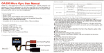
1061 - PhidgetAdvancedServo 8-Motor
Phidgets 1061 - Product Manual
For Board Revision 1
© Phidgets Inc. 2012
Contents
5Product Features
5
Programming Environment
5
Connection
6Getting Started
6
Checking the Contents
6
Connecting all the pieces
6
Testing Using Windows 2000/XP/Vista/7
6
Downloading the Phidgets drivers
6
7
Running Phidgets Sample Program
Testing Using Mac OS X
8
If you are using Linux
8
If you are using Windows Mobile/CE 5.0 or 6.0
9Programming a Phidget
9
Architecture
9
Libraries
9
Programming Hints
9
Networking Phidgets
10 Documentation
10
Programming Manual
10
Getting Started Guides
10
API Guides
10 Code Samples
10 API for the PhidgetAdvancedServo 8-Motor
10
Structures
11
Functions
13
Events
14 Technical Section
14 How RC Servo Motors Work
14 The PhidgetAdvancedServo
14
Current Sense
14
Limitations
14
Degree Abstraction
15
Defining a Custom Servo
15
Degree Abstraction (historical model)
15 Using the 1061 with a Servo Motor
15 Using the 1061 with Continuous Rotation Servos
16 Using the 1061 with Electronic Speed Controllers (ESCs)
16 Connecting your servo motor to the 1061
17 Product History
17 Support
Product Features
• Control the position, velocity, and acceleration of up to 8 RC servo motors
• Requires a 6-15VDC external power supply with center positive polarity.
• High resolution - 125 steps per degree
• Measures current consumption of each servo.
• A switching power supply allows the AdvancedServo to efficiently operate from 6 to 15 VDC, and be used with a
wide range of batteries.
• Switching Regulator protects motors from overvoltage.
• Powers servo motors of up to 3.4 amps.
• Terminal blocks designed for 12-24AWG wires
Programming Environment
Operating Systems: Windows 2000/XP/Vista/7, Windows CE, Linux, and Mac OS X
Programming Languages (APIs): VB6, VB.NET, C#.NET, C++, Flash 9, Flex, Java, LabVIEW, Python, Max/MSP,
and Cocoa.
Examples: Many example applications for all the operating systems and development environments above are
available for download at www.phidgets.com >> Programming.
Connection
The board connects directly to a computer’s USB port.
1061_1_Product_Manual - July 18, 2012 10:19 AM
5
Getting Started
Checking the Contents
You should have received:
• A PhidgetAdvancedServo 8-Motor
In order to test your new Phidget you will also
need:
• Some RC Servo Motors
• A Mini-USB Cable
• A 6 - 15V DC Power Supply with center positive polarity*
* When using a power supply with a barrel connector, make sure
that your power supply has center positive polarity.
Connecting all the pieces
1. Connect the RC Servo Motors to the
PhidgetAdvancedServo.
2. Plug in a power supply using the barrel connector.
1
3. You can also connect a power supply to the Terminal
Block for high-current applications. Be sure to observe
correct polarity.
2
4. Connect the PhidgetAdvancedServo to your computer
using the USB cable.
3
4
Testing Using Windows 2000/XP/Vista/7
Downloading the Phidgets drivers
Make sure that you have the current version of the Phidget library installed on your PC. If you don’t, do the
following:
Go to www.phidgets.com >> Drivers
Download and run Phidget21 Installer (32-bit, or 64-bit, depending on your PC)
You should see the
icon on the right hand corner of the Task Bar.
Running Phidgets Sample Program
Double clicking on the
icon loads the Phidget Control Panel; we will use this program to make sure that your
new Phidget works properly.
The source code for the AdvancedServo-full sample program can be found under C# by clicking on Phidget.com >
Programming.
1061_1_Product_Manual - July 18, 2012 10:19 AM
6
Double Click on the
icon to activate the
Phidget Control Panel and make sure that the
Phidget Advanced Servo Controller 8-Motor
is properly attached to your PC.
1. Double click on Phidget Advanced Servo Controller 8-Motor in
the Phidget Control Panel to bring up AdvancedServo-full and check
that the box labelled Attached contains the word True.
1
2. Select a connected servo. In this example, a servo is connected at
position 0.
3. Select your servo type. If your servo is not in the list, select “default”.
2
4. Use the Velocity slider to set the velocity limit. The servo will try to
accelerate to this point during motion.
3
5. Use the Acceleration slider to set the acceleration.
6. Use the Min/Max Position slider to set the position range. It can
prevent the servo from trying to go beyond its actual range of motion.
7. Check the Engaged box to power the servo. If the servo is not already
the target position, it should begin to move.
10
7
8. Move the Position slider to set a target position. The servo will turn
until its actual position equals the target position. If Speed Ramping
is enabled, the servo will move using the user set acceleration and
velocity.
9
8
4
5
9. When the servo has reached the target position, a tick mark will
appear in the Stopped box.
10. These boxes report the controller’s internally calculated position and
velocity of the servo, as well as current consumed in amps.
6
Testing Using Mac OS X
• Click on System Preferences >> Phidgets (under Other) to activate the Preference Pane
• Make sure that the Phidget Advanced Servo Controller 8-Motor is properly attached.
• Double Click on Phidget Advanced Servo Controller 8-Motor in the Phidget Preference Pane to bring up the
AdvancedServo-full example. This example will function in a similar way as the Windows version.
1061_1_Product_Manual - July 18, 2012 10:19 AM
7
If you are using Linux
There are no sample programs written for Linux.
Go to www.phidgets.com >> Drivers
Download Linux Source
• Have a look at the readme file
• Build Phidget21
There is no Control Panel written for Linux, but there are C/C++ and Java code samples available for all Phidgets
which will compile and run on Linux without modification.
Notes:
Many Linux systems are now built with unsupported third party drivers. It may be necessary to uninstall these
drivers for our libraries to work properly.
Phidget21 for Linux is a user-space library. Applications typically have to be run as root, or udev/hotplug must be
configured to give permissions when the Phidget is plugged in.
If you are using Windows Mobile/CE 5.0 or 6.0
Go to www.phidgets.com >> Drivers
Download x86, ARMV4I or MIPSII, depending on the platform you are using. Mini-itx and ICOP systems will be x86,
and most mobile devices, including XScale based systems will run the ARMV4I.
The CE libraries are distributed in .CAB format. Windows Mobile/CE is able to directly install .CAB files.
The most popular languages are C/C++, .NET Compact Framework (VB.NET and C#). A desktop version of Visual
Studio can usually be configured to target your Windows Mobile Platform, whether you are compiling to machine
code or the .NET Compact Framework.
1061_1_Product_Manual - July 18, 2012 10:19 AM
8
Programming a Phidget
Phidgets’ philosophy is that you do not have to be an electrical engineer in order to do projects that use devices
like sensors, motors, motor controllers, and interface boards. All you need to know is how to program. We have
developed a complete set of Application Programming Interfaces (API) that are supported for Windows, Mac OS X,
and Linux. When it comes to languages, we support VB6, VB.NET, C#.NET, C, C++, Flash 9, Flex, Java, LabVIEW,
Python, Max/MSP, and Cocoa.
Architecture
We have designed our libraries to give you the maximum amount of freedom. We do not impose our own
programming model on you.
To achieve this goal we have implemented the libraries as a series of layers with the C API at the core surrounded
by other language wrappers.
Libraries
The lowest level library is the C API. The C API can be programmed against on Windows, CE, OS X and Linux. With
the C API, C/C++, you can write cross-platform code. For systems with minimal resources (small computers), the C
API may be the only choice.
The Java API is built into the C API Library. Java, by default is cross-platform - but your particular platform may not
support it (CE).
The .NET API also relies on the C API. Our default .NET API is for .NET 2.0 Framework, but we also have .NET
libraries for .NET 1.1 and .NET Compact Framework (CE).
The COM API relies on the C API. The COM API is programmed against when coding in VB6, VBScript, Excel (VBA),
Delphi and Labview.
The ActionScript 3.0 Library relies on a communication link with a PhidgetWebService (see below). ActionScript 3.0
is used in Flex and Flash 9.
Programming Hints
• Every Phidget has a unique serial number - this allows you to sort out which device is which at runtime. Unlike
USB devices which model themselves as a COM port, you don’t have to worry about where in the USB bus you
plug your Phidget in. If you have more than one Phidget, even of the same type, their serial numbers enable
you to sort them out at runtime.
• Each Phidget you have plugged in is controlled from your application using an object/handle specific to that
phidget. This link between the Phidget and the software object is created when you call the .OPEN group of
commands. This association will stay, even if the Phidget is disconnected/reattached, until .CLOSE is called.
• For full performance, the Phidget APIs are designed to be used in an event driven architecture. Applications that
require receiving all the data streaming from the device will have to use event handlers, instead of polling.
Networking Phidgets
The PhidgetWebService is an application written by Phidgets Inc. which acts as a network proxy on a computer. The
PhidgetWebService will allow other computers on the network to communicate with the Phidgets connected to that
computer. ALL of our APIs have the capability to communicate with Phidgets on another computer that has the
PhidgetWebService running.
The PhidgetWebService also makes it possible to communicate with other applications that you wrote and that are
connected to the PhidgetWebService, through the PhidgetDictionary object.
1061_1_Product_Manual - July 18, 2012 10:19 AM
9
Documentation
Programming Manual
The Phidget Programming Manual documents the Phidgets software programming model in a language and device
unspecific way, providing a general overview of the Phidgets API as a whole. You can find the manual at www.
phidgets.com >> Programming.
Getting Started Guides
We have written Getting Started Guides for most of the languages that we support. If the manual exists for the
language you want to use, this is the first manual you want to read. The Guides can be found at www.phidgets.com
>> Programming, and are listed under the appropriate language.
API Guides
We maintain API references for COM (Windows), C (Windows/Mac OSX/Linux), Action Script, .Net and Java. These
references document the API calls that are common to all Phidgets. These API References can be found under www.
phidgets.com >> Programming and are listed under the appropriate language. To look at the API calls for a specific
Phidget, check its Product Manual.
Code Samples
We have written sample programs to illustrate how the APIs are used.
Due to the large number of languages and devices we support, we cannot provide examples in every language for
every Phidget. Some of the examples are very minimal, and other examples will have a full-featured GUI allowing
all the functionality of the device to be explored. Most developers start by modifying existing examples until they
have an understanding of the architecture.
Go to www.phidgets.com >> Programming to see if there are code samples written for your device. Find the
language you want to use and click on the magnifying glass besides “Code Sample”. You will get a list of all the
devices for which we wrote code samples in that language.
API for the PhidgetAdvancedServo 8-Motor
We document API Calls specific to this product in this section. Functions common to all Phidgets and functions not
applicable to this device are not covered here. This section is deliberately generic. For calling conventions under a
specific language, refer to the associated API manual. For exact values, refer to the device specifications.
Structures
enum Phidget_ServoType {
PHIDGET_SERVO_DEFAULT = 1,
PHIDGET_SERVO_RAW_us_MODE,
PHIDGET_SERVO_HITEC_HS322HD,
PHIDGET_SERVO_HITEC_HS5245MG,
PHIDGET_SERVO_HITEC_805BB,
PHIDGET_SERVO_HITEC_HS422,
PHIDGET_SERVO_TOWERPRO_MG90,
PHIDGET_SERVO_HITEC_HS1425CR,
PHIDGET_SERVO_HITEC_HS785HB,
PHIDGET_SERVO_HITEC_HS485HB,
PHIDGET_SERVO_HITEC_HS645MG,
PHIDGET_SERVO_HITEC_HS815BB,
1061_1_Product_Manual - July 18, 2012 10:19 AM
10
PHIDGET_SERVO_USER_DEFINED
}
Used with the ServoType [get,set] functions. These are servos that have been quantified by Phidget Inc. for your
convenience. The Default setting is included for historical reasons, so that the API will be backwards compatible by
default. RAW_us_MODE is used for quantifying new servos, or simply when a microsecond based interface makes
more sense then a degree based abstraction. USER_DEFINED should never be set directly with ServoType - this is
returned when a custom servo type has been defined with setServoParameters.
Functions
int Count() [get]
Returns the number of servos this PhidgetAdvancedServo can control. In the case of the 1061, this will always
return 8. This call does not return the number of servos actually connected.
double Acceleration(int ServoIndex) [get,set]
Acceleration is the maximum change in velocity the PhidgetAdvancedServo uses when speeding up / slowing down a
servo.
• The range of valid Acceleration is bounded by AccelerationMax/AccelerationMin.
• There is a practical limit on how fast your servo can accelerate, based on load and the physical design of the
motor.
• This property should always be set by the user as part of initialization. The value does not initialize to the value
last set on the device.
double AccelerationMax(int ServoIndex) [get] : Constant
AccelerationMax is the upper limit to which Acceleration can be set. For the 1061, this will always return 320000.
double AccelerationMin(int ServoIndex) [get] : Constant
AccelerationMin is the lower limit to which Acceleration can be set. For the 1061, this will always return 19.53125.
double Velocity(int ServoIndex) [get]
Velocity returns the actual velocity that a particular servo is being driven at. A negative value means it is moving
towards a lower position. This call does not return the actual physical velocity of the connected motor.
double VelocityLimit(int ServoIndex) [get, set]
Gets or sets the maximum absolute velocity that the PhidgetAdvancedServo controller will drive the servo. If it’s
changed mid-movement, the controller will accelerate accordingly. If the target position of the controller is near
enough, then the VelocityLimit may never be reached.
• This property should always be set by the user as part of initialization.
• There is a practical limit on how fast your servo can rotate, based on the physical design of the motor.
• The range of VelocityLimit is bounded by VelocityMax/VelocityMin
• Note that when VelocityLimit is set to 0, the servo will not move.
double VelocityMax(int ServoIndex) [get] : Constant
VelocityMax is the absolute upper limit to which Velocity can be set. For the1061, this will always return 6400.
double VelocityMin(int ServoIndex) [get] : Constant
VelocityMin is the absolute lower limit to which Velocity can be set. For the 1061, this will always return 0.
double Position(int ServoIndex) [get,set]
Position is used for both the target and actual position for a particular servo. If the servo is currently engaged and a
new value is set, then the controller will continuously try to move to this position. Otherwise, this call will return the
current position of the servo. This call does not return the actual physical position of the servo.
• The range of Position is bounded by PositionMin/PositionMax
1061_1_Product_Manual - July 18, 2012 10:19 AM
11
• If the servo is not engaged, then the position cannot be read.
• The position can still be set while the servo is not engaged. Once engaged, the servo will snap to position if it is
not there already.
• This property should be set by the user as part of initialization. If not, it will report the last value set on the
device (unless the 1061 has been power-cycled).
• Get will return the last value as reported by the device. This means sets to this value will take a small amount of
time to propagate.
double PositionMax(int ServoIndex) [get,set]
PositionMax is the upper limit to which Position can be set, and is initialized to 233. It can be used to prevent the
controller from going beyond a servo’s range of motion. A PhidgetException will be thrown if this is set above 233
or below PositionMin.
double PositionMin(int ServoIndex) [get,set]
PositionMin is the lower limit to which Position can be set, and is initialized to -22.9921875. It can be used to
prevent the controller from going beyond a servo’s range of motion. A PhidgetException will be thrown if this is set
below -22.9921875 or above PositionMax.
double Current(int ServoIndex) [get]
Current returns the power consumption in amps for a particular servo. The value returned for a disconnected or idle
servo will be slightly above zero due to noise.
bool SpeedRamping(int ServoIndex) [get,set]
SpeedRamping enables or disables whether the PhidgetAdvancedServo tries to smoothly control the motion of a
particular servo. If enabled, then the 1061 will progressively send commands based on velocity, acceleration and
position.
• This property should be set by the user as part of initialization. If not, it will report the last value set on the
device (unless the 1061 has been power-cycled).
• Get will return the last value as reported by the device. This means sets to this value will take a small amount of
time to propagate.
bool Engaged(int ServoIndex) [get,set]
Enables a particular servo to be positioned. If this property is false, no power is applied to the motors. Note that
when it is first enabled, the servo will snap to position, if it is not physically positioned at the same point.
Engaged is useful for relaxing a servo once it’s reached a given position. If you are concerned about keeping
accurate track of position, Engaged should not be disabled until Stopped = True.
• This property should be set by the user as part of initialization. If not, it will report the last value set on the
device (unless the 1061 has been power-cycled).
• Get will return the last value as reported by the device. This means sets to this value will take a small amount of
time to propagate.
bool Stopped(int ServoIndex) [get]
Stopped returns false if the servo is currently in motion. It guarantees that the servo is not moving (unless you are
moving it by hand), and that there are no commands in the pipeline to the servo. Note that virtually any API calls
will cause Stopped to be temporarily false, even changing Acceleration or VelocityLimit on a stopped servo.
Phidget_ServoType ServoType(int ServoIndex) [get,set]
Gets / Sets the servo type for an index. There is a list of some common servos that have been predefined by
Phidgets Inc. This sets the PCM range (range of motion), the PCM to degrees ratios used internally and the
maximum velocity. This allows the degree based functions to be accurate for a specific type of servo.
Note that servos are generally not very precise, so two servos of the same type may not behave exactly the same.
Specific servo motors, as well as servos not in the list, can be independently quantified by the user and set up with
the setServoParameters funtion. This is detailed in the technical section.
1061_1_Product_Manual - July 18, 2012 10:19 AM
12
void setServoParameters(int ServoIndex, double MinUs, double MaxUs, double Degrees, double
VelocityMax)
Sets the parameters for a custom servo motor. MinUs is the minimum PCM in microseconds, MaxUs is the maximum
PCM in microseconds, Degrees is the degrees of rotation represented by the given PCM range and VelocityMax is the
maximum velocity that the servo can maintain, in degrees/second.
Quantifying a custom servo motor is detailed in the technical section.
Events
VelocityChange(int ServoIndex, double Velocity) [event]
An event issued when the velocity changes on a motor.
PositionChange(int ServoIndex, double Position) [event]
An event issued when the position changes on a motor.
CurrentChange(int ServoIndex, double Current) [event]
An event issued when the current consumed changes on a servo.
1061_1_Product_Manual - July 18, 2012 10:19 AM
13
Technical Section
How RC Servo Motors Work
RC Servos are used for positioning applications. They were originally
designed to control Remote Control airplanes and their low cost and high
torque makes them very useful as an actuator in prototyping applications.
An RC Servo can be instructed to move to a desired position by the
controller. Internally, it monitors the current position, and drives the motor
as fast as it can until it reaches the desired position.
This is a very cheap and simple way to control a motor. It has some
limitations - there is no way for the controller to know the current position
and speed of the motor. Applications that want smooth movement suffer
from the aggressive acceleration.
The PhidgetAdvancedServo
The PhidgetAdvancedServo is able to address some of these limitations.
Instead of sending the desired position immediately, the PhidgetAdvancedServo sends a series of progressive
positions according to acceleration and velocity parameters. In most applications, this dramatically smooths the
operation of the servo, and allows reasonably precise control of position, velocity and acceleration.
The PhidgetAdvancedServo has a built in switching regulator - this allows it to efficiently operate from a wide
voltage range (6-15VDC), and maintain proper power to the servo motors even if the power supply is varying. This
built in voltage regulator will not operate if your power supply is undersized.
Current Sense
The PhidgetAdvancedServo continuously measures the current consumed by each motor. The current roughly
corresponds to torque, making it possible to detect several scenarios.
• By monitoring for no current, it’s possible to determine if the servo is not connected. It may not be possible to
distinguish between a servo at rest and a servo not attached.
• Stalled motors can be detected, by monitoring for the maximum current possible with your motor.
• The position limits of the servo can be programmatically determined by moving the servo until it stalls against
the internal or external stops.
Limitations
The PhidgetAdvancedServo does not know the current position of the motor on its own. If your motor is free to
move, and is not being driven beyond the physical limitations of the motor, the position returned to your application
will be very close to the position of the motor.
Degree Abstraction
The PhidgetAdvancedServo software component uses degrees to specify position, velocity, and acceleration.
The degree unit is translated into a pulse sent to the servo, but it’s up to the servo to translate this signal into a
particular position. This translation varies between servo models and manufacturers, and it is up to the user to set
up their particular servo so that the degree abstraction matches up with reality.
Phidgets Inc. has quantified a number of common servo motors (see API section), which can be used with the
ServoType function for to set these parameters. For servos not in this list, or to quantify a specific servo, the
setServoParameters function can be used.
1061_1_Product_Manual - July 18, 2012 10:19 AM
14
Defining a Custom Servo
Servos are driven with a PCM (Pulse Code Modulation) signal. To define a custom servo, you need to find the
minimum and maximum PCM values that the servo supports.
The easiest way to do this is by bringing up the example and choosing RAW_us_MODE. This will display all positions
in microseconds instead of degrees. Move the servo to both of its extremes, stopping when it hits the stops, then
easing up a little (leave a few degrees of leaway), and record these values. You could also choose a specific range in
degrees that you require and find the PCM values that correspond. Most servos operate within 500us - 2500us.
Record the degrees of rotation that this PCM range represents (using a protractor, for example).
Calculate the maximum velocity of your servo, in degrees/second. Most servos list their max speed in sec/60
degrees. convert this into degrees/second:
Velocity(deg/sec) = [(1 / (sec/60deg)) * 60]
The actual maximum velocity of your servo may be slightly higher or lower, as velocity depends on voltage.
Feed these four values into the serServoParameters function to complete the set up. This should be done before any
other function are called (in the attach event ideally).
Note that many servos can operate quite a bit outside of their rated ranges.
Degree Abstraction (historical model)
Historically, our degree abstraction has been based on the Futaba FP-S148 servo. This is the default abstraction
used for the PhidgetAdvancedServo, to maintain backwards compatibility when the new model was added.
PWM(ms)= [(degrees + 23) * 4/375]
Using the 1061 with a Servo Motor
The PhidgetAdvancedServo has been designed to be used with a variety of RC servo motors independent of the
motor-specific position, velocity and torque limits. Select a motor that suits your application and falls within the
PhidgetAdvancedServo device specifications.
To use a servo motor, first select (in software) which attached motor the PhidgetAdvancedServo should affect. Position, velocity and acceleration can be controlled for each individual motor. The software can also display a
readout of the electrical current flowing through each motor. Using the 1061 with Continuous Rotation Servos
A continuous rotation servo is a servo motor that has had its headgear-stop removed and potentiometer replaced
by two matched-value resistors. This has the effect of allowing the motor to rotate freely through a full range of
motion, but disables the motor’s ability to control it’s position.
When using the PhidgetAdvancedServo with a servo motor modified in this way, the position control in software
becomes the motor’s speed control. Because the two resistors that replace the motor’s potentiometer are matched
in value, the motor will always think its shaft is at center position. If the target position in software is set to center,
the motor will believe it has achieved the target and will therefore not rotate. The further away from center the
target position is set to, the faster the motor will rotate (trying to reach that position, but never doing so). Changing
the value above or below center changes the direction of rotation.
1061_1_Product_Manual - July 18, 2012 10:19 AM
15
Using the 1061 with Electronic Speed Controllers (ESCs)
Electronic Speed Controllers are commonly used in RC hobby planes, cars, helicopters. It’s a controller that accepts
a PWM input signal, and controls a motor based on that signal. The ESC accepts power from an external source,
normally a battery pack.
ESCs can be controlled by the 1061, but the vast majority of ESCs on the market will destroy the 1061 if they
are plugged in without modification. In a hobby RC system, the ESC is responsible for regulating some of the
battery current down to ~5V, and supplying it to the radio receiver. An ESC designed to the power the receiver will
advertise that it has a Battery Eliminator Circuit (BEC). When you plug an ESC into the 1061, the 1061 is acting as
the radio receiver. The 1061 was not designed to be powered by the devices it controls, and the voltage regulator
on the 1061 will self-destruct if a device tries to power it. If the center pin from the 3-wire servo connector between
the 1061 and the ESC is disconnected, the BEC on the ESC will not be able to power the 1061, and the voltage
regulator will not fail.
How the ESC inteprets the PWM signal and controls the motor is a function of the ESC. Higher end ESCs can be
configured based on the application.
The hobby RC market has transitioned to Brushless DC Motors (BLDC). As you select an ESC, watch that the battery
voltage input matches that of your system, and the type of motor controlled is what you have. Brushed DC and
Brushless DC Motors are completely different, and require different controllers.
Wiring layout is critical with ESCs. The currents to the motor and on the ground return can be enormous. If these
currents end up travelling back through USB cables, the system will not be stable. Some ESCs are optically isolated
(OPTO) - a big advantage that reduces interference.
Connecting your servo motor to the 1061
The pins on the 1061 are labelled B R W on the board:
• B for Black is the Ground
• R for Red is 5V
• W for White (or Yellow depending on your servo motor) is the Data Line
White (or yellow) Red - 5V Black - Ground
- Data Line
1061_1_Product_Manual - July 18, 2012 10:19 AM
16
Product History
Date
Board Revision
Device Version
Comment
July 2008
0
Product Release
May 2011
0
301
getLabelString fixed for labels > 7 characters
January 2012
1
301
Mini-USB connector, larger input terminal blocks
(12-24AWG)
February 2012
1
302
Prevent signal line startup pulses
Support
Call the support desk at 1.403.282.7335 9:00 AM to 5:00 PM Mountain Time (US & Canada) - GMT-07:00
or
E-mail us at: [email protected]
1061_1_Product_Manual - July 18, 2012 10:19 AM
17
1061_1_Product_Manual - July 18, 2012 10:19 AM
18