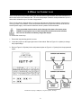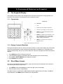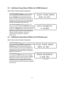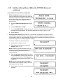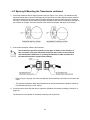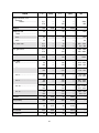
1
DCT7088
PORTABLE DIGITAL CORRELATION
TRANSIT TIME ULTRASONIC FLOWMETER
USER MANUAL
Formerly
P/N 1-0561-007
Rev B (02/03)
USER MANUAL
DCT7088 PORTABLE TRANSIT TIME
ULTRASONIC FLOWMETER
FIRMWARE VERSIONS 6.00 ONWARD
FEBRUARY 2003
REV. B
NOTICE
Read this manual before working with the product. For personal and system safety and for
optimum performance, make sure you thoroughly understand the contents before installing,
using, or maintaining your transit time instrument.
For equipment service needs outside the United States contact your nearest Thermo representative. Within the United States, the Thermo Service Department is your single-point contact for
all Thermo equipment service needs. If at any time you are not sure what to do, you have a
question about using the product, or you have a service or support request, call the center at
(713) 272-0404. This contact is your fastest link to quick and complete answers about any Thermo
product or service.
Thermo Electron Corporation
Process Instruments Division
9303 W. Sam Houston Pkwy S.
Houston, TX 77099
Phone: (713) 272-0404
Fax: (713) 272-5388
Web: www.thermo.com
Acknowledgements for product names used in this manual belong to the following companies:
Dow Corning® is a registered trademark of Dow Corning Corporation.
Excel® for Windows® is either a registered trademark or trademark of Microsoft Corporation.
IBM® is either a registered trademark or a trademark of International Business Machines, Inc.
Krautkramer® is a registered trademark of Agfa-Gevaert Group.
Sil-Glyde® is either a registered trademark or a trademark of American Grease Stick Company.
TABLE OF CONTENTS
1. Product Overview .................................................................................................................................
1.1 Introduction .......................................................................................................................................
1.2 Theory of Operation ..........................................................................................................................
1.3 Transit Time Accuracy ......................................................................................................................
1.4 Ordering ............................................................................................................................................
1.5 Technical Specifications ...................................................................................................................
1.5.1 Performance ................................................................................................................................
1.5.2 Functional ....................................................................................................................................
1.5.3 Physical .......................................................................................................................................
1.6 External Features .............................................................................................................................
1.7 Breakout Box Components ...............................................................................................................
1
1
1
2
3
3
3
3
4
4
5
2. Wiring the Current Loop ...................................................................................................................... 6
3. Configuring & Operating the Flowmeter ............................................................................................. 7
3.1 The Keypad & Display ...................................................................................................................... 7
3.1.1 Components ................................................................................................................................ 7
3.1.2 Display Contrast & Backlight ....................................................................................................... 7
3.2 Direct Menu Access .......................................................................................................................... 7
3.3 Using the Arrow Keys to Access Menus ........................................................................................... 9
3.4 Flowmeter Configuration Using Setup Menus ................................................................................... 9
3.5 Quick Setup Configuration .............................................................................................................. 10
3.6 Primary Displays ............................................................................................................................. 12
3.6.1 Flow/Net Totalizer (00) .............................................................................................................. 12
3.6.2 Flow/Velocity (01) ...................................................................................................................... 12
3.6.3 Flow/Positive Totalizer (02) ....................................................................................................... 12
3.6.4 Flow/Negative Totalizer (03) ...................................................................................................... 13
3.6.5 Signal Strength/Low Signal Cutoff (04) ...................................................................................... 13
3.7 Additional Setup Menus Within the PIPE Submenu* ....................................................................... 13
3.8 Additional Setup Menus Within the LINER Submenu* .................................................................... 14
3.9 Additional Setup Menus Within the FLUID Submenu* ..................................................................... 14
3.10 Additional Setup Menus Within the FLOW Submenu* ................................................................... 15
3.11 Additional Setup Menus Within the TOTAL Submenu* ................................................................. 16
3.12 Additional Setup Menus Within the OPTIONS Submenu* ............................................................. 17
3.13 Additional Setup Menus Within the CALIBR Submenu* ................................................................ 19
3.13.1 Zero Set Calibration ................................................................................................................ 20
3.13.1.a Zero Flow Set Method ........................................................................................................ 20
3.13.1.b Manual Zero Set ................................................................................................................ 21
3.13.2 Scale Factor Calibration .......................................................................................................... 21
3.13.3 Other CALIBR Submenu Options ............................................................................................ 22
3.14 Additional Setup Menus Within the 4-20mA Submenu* ................................................................. 22
3.15 Additional Setup Menus Within the ALARMS Submenu* .............................................................. 23
3.15.1 Programming the Alarm .......................................................................................................... 24
3.15.2 Viewing Alarms ....................................................................................................................... 25
3.16 Additional Setup Menus Within the DATA LOG Submenu* ........................................................... 25
3.17 Additional Setup Menus Within DIAGNOSTICS Submenu* .......................................................... 27
3.18 Additional Setup Menus Within PRINT Submenu* ........................................................................ 27
4. Wiring & Installing the Transducers .................................................................................................
4.1 Wiring .............................................................................................................................................
4.2 Site Selection & Preparation ...........................................................................................................
4.3 Spacing & Mounting the Transducers .............................................................................................
4.4 Transducer Mounting Methods .......................................................................................................
4.4.1 V Method ...................................................................................................................................
4.4.2 W Method ..................................................................................................................................
4.4.3 Z Method ...................................................................................................................................
4.4.4 WV and WW Methods ..............................................................................................................
4.5 Small Pipe Applications ..................................................................................................................
29
29
29
31
33
33
34
34
37
38
5. Emergency Overrides & Master Erase .............................................................................................. 40
5.1 Emergency Overrides ..................................................................................................................... 40
5.2 Performing a Master Erase ............................................................................................................. 40
6. Flowmeter Maintenance & Troubleshooting ....................................................................................
6.1 Replacing the Fuse .........................................................................................................................
6.1.1 Flowmeter Fuse ........................................................................................................................
6.1.2 Breakout Box Fuse ....................................................................................................................
6.2 Charging the Printer Battery ...........................................................................................................
6.3 Charging the Flowmeter ..................................................................................................................
6.4 Replacing Sonic Coupling Compound .............................................................................................
6.5 Troubleshooting & Support .............................................................................................................
6.5.1 General .....................................................................................................................................
6.5.2 Local Representative Support ...................................................................................................
6.5.3 Service & Returns .....................................................................................................................
6.5.4 Upgrades ..................................................................................................................................
6.6 Warranty Statement ........................................................................................................................
41
41
41
41
41
42
42
43
43
43
43
44
44
Appendix A: Pipe Schedules ................................................................................................................. 45
Appendix B: Fluid Properties ................................................................................................................
B.1 Fluid Sound Velocities & Kinematic Viscosities ..............................................................................
B.2 Clean Water Sound Speed Versus Temperature ............................................................................
B.3 Relationship Between Specific Gravity, Viscosity, & Sound Velocity for Petroleum Products ...
49
49
62
63
Appendix C: Monitoring & Downloading Datalogs Using D-Link .......................................................
C.1 Installing D-Link ..............................................................................................................................
C.2 Establishing Communications with a Flowmeter .............................................................................
C.3 Monitoring Datalogs .......................................................................................................................
C.4 Saving & Loading Datalogs ............................................................................................................
64
64
64
65
66
1. PRODUCT OVERVIEW
1.1
Introduction
The DCT7088 Digital Correlation Transit Time Flowmeter is manufactured by Thermo Electron Corporation. This microprocessor-based instrument measures the flow of clean, homogeneous liquids (liquids
without large concentrations of suspended particles or gasses such as air bubbles). The flowmeter is
noninvasive, which means that it measures flow from outside the pipe. Its transducers can be mounted to
a pipe within a matter of minutes, and flow measurements may be made without interrupting the flow or
modifying pipework.
The DCT7088 can be configured using an integral keypad for entering variables such as pipe size, pipe
material, wall thickness, and fluid type (refer to Section 3, page 7). The flowmeter can also be remotely
configured and monitored via the RS232 interface mode using the D-Link data link utility (refer to Appendix
D, page 64). Another alternative to flowmeter configuration is to use the UltraScan utility which also
graphically analyzes the signal in a Microsoft® Windows® environment (UltraScan manual provided on
PolyCD).
1.2
Theory of Operation
Sound waves travel in fluids at a specific velocity depending on the type of fluid. If the fluid is moving, the
sound wave travels at a velocity equal to the sum of the speed of sound in the fluid and the velocity of the
fluid itself relative to the transducer. A sound wave traveling in the same direction as the fluid flow (downstream) will arrive sooner than a sound wave traveling against the flow (upstream). A transit time flowmeter operates by measuring both the absolute travel time of each sound wave and the difference in time
required for the waves to travel between an externally mounted downstream and upstream transducer
(Figure 1.2-A, below). Based on the transit time of the 2 sound waves, the flowmeter calculates the
average fluid velocity.
FIGURE 1.2-A: TYPICAL TRANSIT TIME SYSTEM
Once the differential transit time is calculated, several additional variables must be taken into consideration. The overall velocity of the fluid is actually made up of many individual local velocities that vary
according to their distance from the pipe wall. The velocities in the center of the pipe are higher than the
velocities near the pipe wall. The combination of these individual velocities for a specific type of fluid within
a specific pipe yield a velocity distribution known as the flow profile (Figure 1.2-B, page 2), which is a
function of the Reynolds number. By properly configuring the flowmeter, the effects of the flow profile are
taken into consideration when calculating the mean fluid velocity. The flowmeter then multiplies this
velocity by the pipe’s cross-sectional area to obtain volumetric flow.
1
FIGURE 1.2-B: FLOW PROFILES
1.3
Transit Time Accuracy
Noninvasive ultrasonic measurements are subject to a variety of effects that can influence measurement
accuracy. All ultrasonic instruments are velocity measuring devices and only infer volumetric flow from the
operator-entered parameter of pipe inside diameter (ID). When this value is squared to get cross-sectional
area, a 1% error yields a 2% error in volumetric flow. In practice, commercially fabricated pipe seldom has
ID consistency much tighter than 1%, and unless the pipe to be measured has been accurately measured,
this uncertainty is not reducible through instrument calibration.
The more sophisticated transit time flowmeters incorporate flow profile corrections to compensate for the
pipe’s cross-sectional velocity profile with a changing Reynolds number. However, this requires that the
operator knows the inside roughness of the pipe to be measured. The instrument may infer a roughness if
none is entered by the operator, but that is only an estimate based on the characteristics of new pipe.
Pipes can, of course, accumulate deposits which may not only reduce the ID, but affect the roughness as
well. Errors on the order of 2% as a result of this phenomenon are not uncommon.
While other factors may influence instrument accuracy to a lesser extent, the issues described above are
the major elements of pipe dependency upon absolute instrument accuracy. While calibration on a reference flow loop under known conditions is a useful exercise to determine the accuracy potential of an
instrument, it is not a guarantee of absolute accuracy on different pipes under field conditions.
2
1.4
Ordering
The table below describes ordering information for a standard DCT7088 flowmeter as well as available
options.
MODEL NUMBER
Series: Digital Correlation Transit Time Flowmeters
DCT7088 = DCT7088, RS232 digital interface with UltraScan signal analysis and configuration program
Battery Duration
1 = 8 hours1
2 = 16 hours
Transducer Cable Length
16A = 16 ft (5 m)1
XXXXA = increments of 10 ft (3 m) up to 1000 ft (305 m)
Additional Options
0704/0188 =
Ultrasonic Thickness Gauge (UTG), English units
0704/0187 =
UTG, metric units
22334-0001 = Thermal printer kit
Typical Model Number: DCT7088-1-B-16A
1
standard
TABLE 1: ORDERING INFORMATION
1.5
Technical Specifications
1.5.1 Performance
Flow range:
Accuracy:
Sensitivity:
Linearity:
Pipe size:
Fluid:
0 to 40 ft/s (0 to 12 m/s)
+/-1% of velocity or +/-0.05 ft/s (+/-0.0152 m/s), typical, digital output
0.001 ft/s (0.3 mm/s) at any flow rate, including zero
+/-0.1% of scale, digital output
1 to 200 in (25 mm to 5 m)
homogeneous liquids without gas bubbles
1.5.2 Functional
Outputs:
Power supply:
Keypad:
Display:
Datalogger:
Programming:
Temperature Range:
4-20 mA (into 1000 ohms), 12-bit, isolated, loop- or self- powered
RS232 serial interface
built-in lead acid gel battery providing 8 hours continuous operation
(standard) OR 16 hours continuous operation (optional)
19-key with tactile action
40-character, 2-line, alphanumeric, backlit LCD
40,0000 points, time stamped; programmable in 1-second intervals
via UltraScan utility (supplied with flowmeter) OR integral keypad
Transducers: -40º to +212º F (-40º to +100º C)
optional high temperature transducers available
Transmitter:
-5º to +140º F (-20º to +60º C)
3
...1.5 Technical Specifications continued
1.5.3 Physical
Transmitter:
Transducers:
Weight:
1.6
NEMA 6 (IP67), waterproof against accidental immersion; splashproof with lid
open
encapsulated design with standard 16 ft (5 m) cable length
approximately 11 lbs (4.9 kg) with 8-hour battery;
approximately 15 lbs (6.8 kg) with 16-hour battery
External Features
Components
4
#
Description
1
Printer port: provides output for
optional external thermal printer;
connects to special cable which has
3-pin round connector on flowmeter
end and DB9 connector on printer
end
2
ON/OFF keys
3
Battery Low light: activates
approximately 7 or 14 hours of
operation (depending on battery
type); automatic shutdown after
approximately 1 additional hour
4
Charging light
5
Instrument on light
6
Fuse: 3-A, 250 V; protects
flowmeter from battery overcurrent
or short circuits
7
Liquid crystal display (LCD):
displays configuration selections,
flow rate, totalized flow, etc.
8
Keypad: use to enter configuration
parameters and control flowmeter
functions
9
Downstream transducer connector
10
Upstream transducer connector
11
Breakout box interface connector:
connects flowmeter to breakout box
1.7
Breakout Box Components
Components
5
#
Description
1
AC power cable
2
DC power output cable
3
DC power input connector: connects
DC power output cable to flowmeter
4
4-20 mA output terminals
5
Printer charger cable
6
RS232 serial port
7
Breakout box interface connector:
provides connections for DC power
input from battery charger/AC
adapter, for DC output cable for
charging batter, for RS232 serial
port, and for 4-20 mA current loop
output terminals
8
7-pin circular connector: connects
breakout box to flowmeter
2. WIRING THE CURRENT LOOP
The 4-20 mA current loop module has an input terminal and an output terminal, which are indicated on a
label on the inside of the flowmeter door. The current loop output is rated for a loop resistance of up to 1 k
ohms and is isolated for up to 5 kV when loop-powered.
The 4-20 mA module is shipped with the current loop self-powered. Switch the module to loop power by
moving a jumper on the module. Current loop modules which are loop-powered must be driven from an
external power supply. In this case the flowmeter acts as a passive 2-wire transmitter.
Prevent possible electrical shock and/or damage to the meter–disconnect power
PRIOR to removing back cover of the breakout box and disconnect the breakout
box from the flowmeter and battery charger/AC adapter.
To connect the current loop:
1. Ensure the loop powering option is correct.
2. Locate the jumpers on the upper right corner of the module. Refer to Figure 2.1-A (below) to change
the jumper settings.
3. Refer to Figure 2.1-B (below) for the self-powered option or Figure 2.1-C (below) for the loop-powered
option.
FIGURES 2.1-A (LEFT), 2.1-B (RIGHT, TOP), 2.1-C (RIGHT, BOTTOM)
6
3. CONFIGURING & OPERATING THE FLOWMETER
3.1
The Keypad & Display
The keypad provides access to the microprocessor for flowmeter configuration. During operation, the
instrument’s 40-character LCD indicates flow rate and totalizer values.
3.1.1 Components
Components
#
Description
1
LCD
2
Numeric keys: 0 through 9 and decimal (.)
3
Arrow keys: for scrolling up, down, left, right
4
ENTER key: operates like the Return (Enter)
key on a computer
5
ERASE key: deletes last value entered; in most
setup anddiagnostic menus, accesses Main
Menu; accesses Menu 00 (flow rate and net
totalizer display) if pressed twice
6
MENU key: provides access to setup and
diagnostic menus
FIGURE 3: KEYPAD & DISPLAY FEATURES
3.1.2 Display Contrast & Backlight
The display is backlit for ease of viewing in low-light conditions. In order to save battery life, the backlight
shuts off automatically after several minutes have passed without a keypad entry. The display has a
variable contrast setting, and you may need to adjust the contrast on the display as ambient temperature
changes:
1.
2.
3.
4.
Press MENU followed by the ± (plus/minus) key.
LCD CONTRAST appears on the display with a bar indicating current contrast setting.
Press LEFT or RIGHT ARROW keys to adjust the contrast.
Press ENTER when complete.
3.2
Direct Menu Access
The unique 2-digit address (reference Table 2, page 8) for each setup and diagnostic menu allows the
user to directly access the desired menu:
1. Press MENU, and the letter M appears in the lower right corner of the display.
2. Enter the desired menu’s 2-digit address.
The address must be entered while the M is displayed (within approximately 4 seconds). If the M is no
longer displayed, press MENU again followed by the 2-digit address.
7
Table 2: Menu Addresses
Menu Type
Display
Menu Menu Type
Display
Menu
Primary
Flow/Net Totalizer
Flow/Velocity
Flow/Positive Totalizer
Flow/Negative Totalizer
Signal Strength/Low Signal
Cutoff
00
01
02
03
04
Measurement Units
Site Parameters
RS232 Configuration
Change System Password
Change Scale Factor
Password
Unit ID
42
43
46
47
48
Pipe
Pipe OD
Pipe Wall Thickness
Pipe ID
Pipe Material
Pipe Sound Speed
Pipe Inside Roughness
10
11
12
13
14
15
Liner Material
Liner Thickness
Liner Sound Speed
Liner Inside Roughness
16
17
18
19
Fluid Type
Fluid Sound Speed
Fluid Viscosity
20
21
22
Alarms
Transducer Type
Transducer Mounting
Transducer Spacing
23
24
25
Flow Units
Max Flow Range
Min Flow Range
Damping
Low Flow Cutoff
Low Signal Cutoff
30
31
32
33
34
35
Totalizer Units
Totalizer Multiplier
Net Totalizer
Positive Totalizer
Negative Totalizer
Totalizer Reset
36
37
38
39
40
41
Liner
Fluid
Transducer
Flow
Totalizer
Options
Calibration
Zero Set
Scale Factor
Sound Speed
Compensation
Date and Time
Current Loop
49
50
51
52
53
54
Current Loop Span
Current Loop Calibration
Current Loop Test
56
57
58
59
Program Alarms
View Alarms
70
71
72
Datalog
Datalog Setup
Datalog Interval
80
81
Diagnostics
Signal Strength/Margin
Delta Time/Fluid Sound
Speed
Reynolds #/Profile Factor
Current Loop Output
Software/Firmware Rev.
Level
90
91
Print
8
Print Log Setup
Print Settings
Print Diagnostic
Print Current Screen
92
93
94
96
97
98
99
3.3
Using the Arrow Keys to Access Menus
Another method of accessing the flowmeter’s menus is to use the LEFT or RIGHT ARROW keys to scroll
through the menu structure. Menus are organized into 3 basic levels: 1) Main menu, 2) submenus, and 3)
primary displays, setup menus, diagnostic menus. The Main menu displays various submenus, which
contain individual setup and diagnostic menus.
To access the Main menu from any screen:
1. Press MENU twice. The Main menu is displayed with
the Pipe and Liner submenu options as shown in
Figure 3.3-A.
FIGURE 3.3-A
2. To view the remaining submenus (Figure 3.3-B),
press the DOWN ARROW key.
FIGURE 3.3-B
3. When the desired submenu is highlighted, press
ENTER to display the first menu of the selected
submenu. Figure 3.3-C is an example of when the
Flow submenu is selected.
FIGURE 3.3-C
Use the UP or DOWN ARROW keys to view a Primary Display, setup menu, or diagnostic menu within the
current submenu.
3.4
Flowmeter Configuration Using Setup Menus
Flowmeter configuration is accomplished using the setup menus. Some setup menus allow a numeric
value to be entered, and others offer non-numeric selections. In non-numeric setup menus, an asterisk is
displayed to the left of the selected currently entered in the flowmeter (Figure 3.4, below).
FIGURE 3.4
9
...3.4 Flowmeter Configuration Using Setup Menus continued
To configure the flowmeter:
1. Access the setup menus individually by pressing MENU and entering the 2-digit address OR by
scrolling through the submenus and selecting the desired setup menu.
2. a. If the setup menu requires a numeric entry, use the numeric keys to enter the value and press
ENTER to accept the value. If the numeric value is entered incorrectly, press ERASE to delete the
entry.
OR
b. If the setup menu offers a non-numeric selection, press ENTER, and the asterisk changes to a
flashing cursor. Use the arrow keys to scroll through the available selections. When the cursor is
to the left of the desired selection, press ENTER.
3. Complete the configuration process by accessing a Primary Display (menus 00 through 04).
The flowmeter will not use the new parameters until accessing a Primary Display.
3.5
Quick Setup Configuration
The Quick Setup procedure contains the minimal steps required for flowmeter configuration. These steps
enable the flowmeter to calculate transducer spacing, acquire ultrasonic signal, and measure flow. The
number in parentheses after the required menu is the 2-digit address to directly access that menu.
1. Select a proper transducer site according to Section 4 (page 29).
2. Access the Pipe submenu. This submenu contains setup menus related to the pipe parameters such
as pipe inside diameter (ID) and pipe outside diameter (OD).
Pipe Wall Thickness is an additional setup menu within the Pipe submenu. If
parameters for any 2 of the following 3 setup menus are entered, the flowmeter
calculates the remaining parameter automatically: Pipe OD (10), Pipe Wall
Thickness (11), Pipe ID (12).
Accuracy is directly affected by the square of an error in pipe dimensions; actual
measurements (not nominal) must be entered.
a. Select the PIPE OD menu (10). Figure 3.5-A
is displayed. Enter the value for the pipe OD and
press ENTER. Press the DOWN ARROW, and
select Actual.
NOTE: If you know the pipe circumference but not the
OD, enter the circumference value instead and press
ENTER. Press the DOWN ARROW, and Figure 3.5-B
is displayed. Select Circum. The flowmeter calculates
the pipe OD automatically.
FIGURE 3.5-A
FIGURE 3.5-B
10
...3.5 Quick Setup Configuration continued
Step 2, PIPE setup menu continued:
b. Select the Pipe ID setup menu (12). Enter the
pipe ID value, and press ENTER. (Figure 3.5-C)
c.
Select the Pipe Material setup menu (13). Press
the UP and DOWN ARROWS to scroll through
the available options. (Figure 3.5-D)
FIGURE 3.5-C
NOTE: Select OTHER if the material is not listed.
You must then enter then pipe sound speed (14) and
pipe inside roughness (15).
FIGURE 3.5-D
3. If there is a liner:
a. Access the Liner Material setupmenu (16), and
Figure 3.5-E is displayed. Press the UP and
DOWN ARROWS to scroll through the available
options.
FIGURE 3.5-E
NOTE: Select OTHER if the material is not listed.
You must then enter the liner sound speed (18) and
liner inside roughness (19).
b. Access the Liner Thickness setup menu (17),
and enter the thickness. (Figure 3.5-F)
FIGURE 3.5-F
4. Access the Fluid Type setup menu (20), and scroll
through the available options using the UP and
DOWN ARROWS. (Figure 3.5-G)
NOTE: Select OTHER if the fluid type is not listed.
You must then enter the fluid sound speed (21) and
fluid viscosity (22).
FIGURE 3.5-G
5. Within the Transducer submenu:
a. Access the Transducer Type setup menu (23).
Currently, the only selection available is
STANDARD, which MUST be selected for all
applications using clamp-on transducers,
including high temperature transducers.
(Figure 3.5-H)
b. Access the Transducer Mounting setup menu
(24), and select the desired mounting method.
(Figure 3.5-I)
6. Access the Transducer Spacing view-only menu
(25). Note the required spacing between transducers.
(Figure 3.5-J)
11
FIGURE 3.5-H
FIGURE 3.5-I
FIGURE 3.5-J
...3.5 Quick Setup Configuration continued
7. Access the Flow Units setup menu (30) within the
FLOW submenu. Use this setup menu to select the
flow rate units. Volumetric units are displayed first,
followed by the associated time per units.
FIGURE 3.5-K
a. Select one of the available volumetric units.
(Figure 3.5-K)
b. Press the DOWN ARROW and the time per unit
options are displayed. Select the desired option.
(Figure 3.5-L)
8. Install the transducers on the pipe using the spacing
provided by the flowmeter, and connect the
transducer cables to the flowmeter.
FIGURE 3.5-L
9. Access a Primary Display (00 through 04) to complete the configuration process.
If the flowmeter and transducers are properly installed and a steady flow is present, the flow and signal
strength readings should be relatively stable.
If any of the above setup parameters are changed, the flowmeter stops measuring
flow until the new value is entered and a Primary Display is accessed to accept
the new value.
3.6
Primary Displays
The Primary Displays are for viewing only and cannot be configured. Primary Displays include displayed
values for flow rate, totalizers, velocity, signal strength, or low signal cutoff (menus 00 through 04).
3.6.1 Flow/Net Totalizer (00)
The Flow/Net Totalizer is the standard display used
under normal operating conditions. It displays the flow
rate and net totalizer value. If the net totalizer is not
currently enabled, the last net totalized value is displayed.
(Figure 3.6-A)
FIGURE 3.6-A
3.6.2 Flow/Velocity (01)
The Flow/Velocity display indicates the flow rate and
fluid velocity. Velocity is displayed in feet per second
(FPS) if ENGLISH is selected as the measurement unit in
Menu 42 and in meters per second (MPS) if METRIC is
selected. (Figure 3.6-B)
FIGURE 3.6-B
3.6.3 Flow/Positive Totalizer (02)
This display indicates the flow rate and the totalized flow
in the positive flow direction. If the positive totalizer is not
currently enabled, the last net totalized value is displayed.
(Figure 3.6-C)
12
FIGURE 3.6-C
3.6.4 Flow/Negative Totalizer (03)
This display indicates the flow rate and the totalized flow
in the negative flow direction. If the negative totalizer is
not currently enabled, the last net totalized value is
displayed. (Figure 3.6-D)
3.6.5 Signal Strength/Low Signal Cutoff (04)
FIGURE 3.6-D
This display indicates the values for signal strength and
low signal cutoff. (Figure 3.6-E)
FIGURE 3.6-E
3.7
Additional Setup Menus Within the PIPE Submenu*
*Not included in the Quick Setup Configuration
Following are setup menus not included in the Quick Setup Configuration detailed in Section 3.5 (page
10). Setup menus are used primarily to enter configuration data or to view the flowmeter’s current configuration settings. The following setup menus are located within the PIPE submenu and are not required
entries in the Quick Setup Configuration:
•
Pipe Wall Thickness setup menu (11) (Figure 3.7-A)
•
Pipe Sound Speed setup menu (14): This menu can
only be configured if OTHER was selected as the
pipe material in Menu 13. Enter the pipe sound
speed. If OTHER was NOT selected as the pipe
material, this menu is available by the direct access
method only and functions as a view-only display to
indicate the pipe sound speed as programmed in the
flowmeter’s database. (Figure 3.7-B)
•
Pipe Inside Roughness setup menu (15): This menu
can only be configured if OTHER was selected as the
pipe material in Menu 13. Data on this parameter are
available from the Cameron Hydraulic Data Book
published by Ingersoll-Rand. Enter the inside
roughness of the pipe. If OTHER was NOT selected
as the pipe material, this menu is available by the
direct access method only and functions as a viewonly display to indicate the pipe inside roughness as
programmed in the flowmeter’s database.
(Figure 3.7-C)
13
FIGURE 3.7-A
FIGURE 3.7-B
FIGURE 3.7-C
3.8
Additional Setup Menus Within the LINER Submenu*
*Not included in the Quick Setup Configuration
•
•
Liner Sound Speed setup menu (18): This menu can
only be configured if OTHER was selected as the
liner material in Menu 16. Enter the liner sound
speed. If OTHER was NOT selected as the liner
material, this menu is available by the direct access
method only and functions as a view-only display to
indicate the liner’s sound speed as programmed in
the flowmeter’s database. (Figure 3.8-A)
Liner Inside Roughness setup menu (19): This
menu can only be configured if OTHER was selected
as the liner material in Menu 16. Enter the liner inside
roughness. If OTHER was NOT selected as the liner
material, this menu is available by the direct access
method only and functions as a view-only display to
indicate the inside roughness of the liner as
programmed in the flowmeter’s database.
(Figure 3.8-B)
3.9
FIGURE 3.8-A
FIGURE 3.8-B
Additional Setup Menus Within the FLUID Submenu*
*Not included in the Quick Setup Configuration
•
•
Fluid Sound Speed setup menu (21): This menu can
only be configured if OTHER was selected as the fluid
type in Menu 20. Enter the fluid sound speed. If
OTHER was NOT selected as the fluid type, this
menu is available by the direct access method only
and functions as a view-only display to indicate the
fluid sound speed as programmed in the flowmeter’s
database. (Figure 3.9-A)
Fluid Viscosity setup menu (22): This menu can only
be configured if OTHER was selected as the fluid
type in Menu 20. Enter the fluid viscosity. If OTHER
was NOT selected as the fluid type, this menu is
available by the direct access method only and
functions as a view-only display to indicate the fluid
viscosity as programmed in the flowmeter’s database.
(Figure 3.9-B)
14
FIGURE 3.9-A
FIGURE 3.9-B
3.10 Additional Setup Menus Within the FLOW Submenu*
*Not included in the Quick Setup Configuration
•
Max Flow Range setup menu (31) and Min Flow
Range setup menu (32): Use these menus to
enter the minimum and maximum flow values for
setting the volumetric flow range. Setting the optimum
flow range generally improves the flowmeter’s
response time. (Figures 3.10-A and 3.10-B)
NOTE: Whenever the pipe ID is changed, the
flowmeter returns the volumetric flow range to its
default settings. The default settings are the minimum
and maximum flows for the new pipe ID that occur at
+32 and -32 ft/s (+9.76 and -9.76 m/s).
•
•
Damping setup menu (33): Use this menu to enter
the value for the damping coefficient, which
suppresses short-term fluctuations in the indicated
flow rate. The displayed flow rate and the 4-20 mA
current loop output is a moving average of the last n
seconds where n is the damping value. Increasing the
coefficient increases the response time to changes.
The coefficient is adjustable from 1 to 99 seconds in
1-second increments. Damping should be kept at a
minimum unless the flow rate fluctuates wildly. If this
is the case, increase the damping coefficient just
enough to reduce the fluctuation to an acceptable
degree. (Figure 3.10-C)
Low Flow Cutoff setup menu (34): When a zero flow
condition occurs (for example, as the result of a pump
being shut off), internal sloshing, check valve
leakage, and other fluid movement can prevent the
flowmeter from reading total zero. This phenomenon
can result in totalizer errors. Minimize these errors by
entering a low flow cutoff, which drives the flowmeter
to zero for flow rates at or below the specified value. If
the flow rate falls below the low flow cutoff value, the
indicated flow rate is driven to zero and the totalizers
stop incrementing; this is the case regardless of flow
direction. (Figure 3.10-D)
For example, if you enter a low flow cutoff of 0.1 ft/s
(.03 m/s), the flowmeter is driven to zero for flow rates
less than 0.1 ft/s in the positive direction and greater
than -0.1 ft/s in the negative direction. (Figure 3.10-E)
15
FIGURE 3.10-A
FIGURE 3.10-B
FIGURE 3.10-C
FIGURE 3.10-D
FIGURE 3.10-E
...3.10
Additional Setup Menus Within the FLOW Submenu*
continued
*Not included in the Quick Setup Configuration
•
Low Signal Cutoff setup menu (35): Empty pipes or solids, bubbles, or voids in the flow stream may
cause temporary drops in signal strength and erroneous readings. Minimize the effect of these
dropouts by setting a low signal cutoff, which drives the flowmeter to the loss-of-signal (LOS)
condition. The low signal cutoff should be set at the minimum acceptable signal amplitude.
To set the low signal cutoff:
a. Access the Low Signal Cutoff setup menu (35).
(Figure 3.10-F)
b. Enter the low signal cutoff and press ENTER.
FIGURE 3.10-F
NOTE: The value for the low signal cutoff should
usually be set at approximately one-half of the value
of the signal strength present under flow conditions.
Typically, signal strength is not significantly affected
by flow rate.
FIGURE 3.10-G
c.
Select one of the following:
•
ZERO: the flowmeter drops the reading to zero during LOS condition;
•
HOLD: the flowmeter holds the last valid reading during LOS condition for about 3
seconds. (Figure 3.10-G)
3.11 Additional Setup Menus Within the TOTAL Submenu*
*Not included in the Quick Setup Configuration
•
Totalizer Units setup menu (36): The flow unit
selected for the totalizer display may be different from
the flow unit selected for the flow rate display.
(Figure 3.11-A)
•
Totalizer Multiplier setup menu (37): The totalizer
value can be displayed with one of several multiplier
values. For example, 700 liters can be displayed as
700 if the selected multiplier value is X1, or it can be
displayed as 7 if selected multiplier value is X100.
(Figure 3.11-B)
•
Net Totalizer setup menu (38): Use this menu to
enable or disable the net totalizer. The net totalizer
provides the difference between the positive and
negative flow values. For example, if there are 1000
gallons of flow in the negative direction and 3000
gallons of flow in the positive direction, the net
totalizer indicates 2000 gallons of net flow.
(Figure 3.11-C)
16
FIGURE 3.11-A
FIGURE 3.11-B
FIGURE 3.11-C
...3.11
Additional Setup Menus Within the TOTAL Submenu*
continued
*Not included in the Quick Setup Configuration
•
•
•
Positive Totalizer setup menu (39): Use this menu to
enable or disable the positive totalizer. The positive
totalizer tracks the flow that moves in the positive
direction, from upstream transducer to downstream
transducer. It is NOT affected by flow in the opposite
direction. (Figure 3.11-D)
Negative Totalizer setup menu (40): Use this menu
to enable or disable the negative totalizer. The
negative totalizer tracks the flow that moves in the
negative direction, from downstream transducer to
upstream transducer. It is NOT affected by flow in the
opposite direction. (Figure 3.11-E)
FIGURE 3.11-D
FIGURE 3.11-E
Totalizer Reset setup menu (41): Use this menu to
reset one or all of the totalizers. (Figure 3.11-F)
FIGURE 3.11-F
3.12 Additional Setup Menus Within the OPTIONS Submenu*
*Not included in the Quick Setup Configuration
The OPTIONS submenu contains setup menus for several miscellaneous functions.
•
Measurement Units setup menu (42): Use this menu
to select ENGLISH (feet per second, FPS) or
METRIC (meters per second, MPS) measurement
units. (Figure 3.12-A)
•
Site Parameters setup menu (43): This menu saves
the parameters for the pipe, liner, fluid, transducer,
and flow setup menus, allowing them to be recalled
later for a specific measurement site. Several sites
are available and are numbered. The site number is
displayed in Menu 43 in the lower left corner of the
screen and is followed by a colon. See Figure 3.12-B
for an example of a site numbered 1.
FIGURE 3.12-A
FIGURE 3.12-B
As the setup parameters are entered in their respective menus during normal configuration, the same
parameters are saved simultaneously in the Site Parameters setup menu, in whichever site has the
asterisk displayed.
Access a different site to automatically enter that site’s stored parameters into the flowmeter for
measuring flow. To access a different site, press ENTER, scroll to the desired site, and press ENTER
again. To avoid overwriting stored parameters and losing old data, ensure that the desired site
is active prior to entering the new set of parameters.
17
...3.12
Additional Setup Menus Within the OPTIONS Submenu*
continued
*Not included in the Quick Setup Configuration
•
RS232 Configuration setup menu (46): Use this
menu to configure the RS232 port which allows the
flowmeter to connect to an IBM®-compatible PC using
the UltraScan (refer to the UltraScan manual) or
D-Link (refer to Appendix C, page 64) utilities.
(Figure 3.12-C)
FIGURE 3.12-C
a. Access the RS232 Configuration setup menu
(46).
b. Select ULTRASCAN or D-LINK.
c.
FIGURE 3.12-D
Press the DOWN ARROW to display the baud rate selections. The baud rate is the only RS232
parameter that can be selected. The remaining parameters are preset. (Figure 3.12-D)
d. Access Menu 00.
•
Change System Password setup menu (47): The flowmeter is shipped from the factory with the
system password disabled. If a password is enabled, the flowmeter requests the password when a
user attempts to enter any configuration data. Entering the correct password temporarily unlocks the
system, allowing the user to make configuration changes.
To change or disable the system password:
a. Access Menu 47. (Figure 3.12-E)
b. Enter the new system password and press
ENTER. (Figure 3.12-F)
FIGURE 3.12-E
NOTE: Disable the system password function by
entering 0 (zero) as the system password. Enable the
function by changing the password back to a
non-zero number.
c.
Enter the old system password (Figure 3.12-G)
and press ENTER. If the old system password is
correctly entered, Figure 3.12-H is displayed. If
the password is incorrectly entered, Figure 3.12-I
is displayed.
FIGURE 3.12-F
FIGURE 3.12-G
NOTE: After the system password is accepted or
rejected, Menu 48 is displayed, enabling the scale
factor password to be changed.
d. Access Menu 00 to lock the system with the new
password.
FIGURE 3.12-H
FIGURE 3.12-I
18
...3.12
Additional Setup Menus Within the OPTIONS Submenu*
continued
*Not included in the Quick Setup Configuration
•
Change Scale Factor Password setup menu (48):
Use this menu to change the scale factor password
which is designed to protect the scale factor from
unauthorized or accidental changes. The flowmeter
ships from the factor with the scale factor password
disabled. If the scale factor password is enabled, the
flowmeter requests the password whenever a user
attempts to change the scale factor.
FIGURE 3.12-J
To change or disable the scale factor password:
FIGURE 3.12-K
a. Access Menu 48. (Figure 3.12-J)
b. Enter the new scale factor password and press
ENTER. (Figure 3.12-K)
NOTE: The system password function must be
disabled to allow the scale factor to be changed
without entering a password.
c.
FIGURE 3.12-L
Enter the old scale factor password and press
ENTER. If entered correctly, Figure 3.12-L is
displayed. If entered incorrectly, Figure 3.12-M is
displayed.
FIGURE 3.12-M
d. Access Menu 00.
•
Unit ID (identification) Number setup menu (49):
This number is determined by the operator to identify
the specific instrument or site. Any whole number
between 1 and 60,000 may be entered.
(Figure 3.12-N)
FIGURE 3.12-N
3.13 Additional Setup Menus Within the CALIBR Submenu*
*Not included in the Quick Setup Configuration
Within the CALIBR submenu is the Calibration Group menu (50) (Figure 3.13-A), which contains 4 setup
menus: Zero Set, Scale, SS Comp, Date (Menus 51 through 54).
FIGURE 3.13-A
19
3.13.1 Zero Set Calibration
An important step in assuring accurate flow measurement is the proper calibration of the instrument and
proper installation. The calibration methods must be performed for the particular pipe that is to be metered.
Table 3 (below) provides guidelines for selecting a calibration method.
Calibration Method
Zero set calibration
Zero flow set
Manual zero set
Scale factor
Function
Application
Zeroes the instrument for an actual
no flow condition
Applies a manually entered offset to
all flow readings
Compensates for manufacturing
variations in the transducers
Installations where flow can be
stopped
Where an offset is required
Set by the factory to the value
imprinted on the transducers
TABLE 3
After installing the meter, you may find that a small adjustment to the zero point (zero set calibration) is
required. Zero set calibration allows the meter to read very close to zero under zero flow conditions. There
are 2 zero set calibration methods in Menu 51: the zero flow set method and the manual zero set method.
View the zero point used by the flowmeter in either of these methods by selecting Manual in Menu 51.
After the instrument is properly zeroed, it should display a stable reading well below 0.05 ft/s (0.015 m/s)
under zero flow conditions with the low flow cutoff disabled.
Prior to performing a zero set calibration, verify the following:
•
•
•
transducers are connected to the pipe;
instrument is reading flow;
low flow cutoff is disabled to allow verification of calibration.
3.13.1.a
Zero Flow Set Method
The best method of zeroing the instrument is to stop the flow and perform a zero flow set on the pipe. The
purpose of the zero flow set is to zero the instrument for the individual application. This method is used
only when flow in the pipe can be stopped. The flow rate displayed in Menu 01 must be between -0.25 and
+0.25 ft/s (-0.076 and +0.076 m/s).
1. Ensure there is no flow in the pipe.
2. Access Menu 51. (Figure 3.13-B)
3. Select No Flow. If the zero flow set calibration is
successful, Figure 3.13-C is displayed.
FIGURE 3.13-B
FIGURE 3.13-C
20
3.13.1.b
Manual Zero Set
Use this method infrequently. Manual zero set applies a constant offset entered by the user to all readings.
For example, if the flow reads 250 GPM and a 10 GPM offset is applied, the new reading becomes
240 GPM.
To zero the instrument using the manual zero set method:
1. Minimize flow occurring in the pipe.
2. Access Menu 51 and select Manual. Figure 3.13-D is
displayed.
3. Enter the value of the required offset and press
ENTER. If necessary, you can apply a negative offset
by pressing ± (plus/minus key).
4. The flowmeter is now calibrated with the manual zero
set method, and the zero point offset is displayed.
(Figure 3.13-E)
FIGURE 3.13-D
FIGURE 3.13-E
3.13.2 Scale Factor Calibration
After setting and verifying the instrument’s zero point, you can set a scale factor to adjust the measured
flow; the measured flow is multiplied by this scale factor. For example, if the displayed flow is twice the
actual flow, you can enter a scale factor of 0.5 to divide the displayed flow by 2. The primary reason for
setting the scale factor is to compensate for manufacturing variations in the transducers. The scale factor
printed on the transducer set should be entered in Menu 52.
Observe the following precautions when setting the scale factor:
•
Always determine the scale factor at the highest possible flow rate achievable in order to maximize
accuracy of the scale factor.
•
Use only the factory preset scale factor as marked on the transducers in the following situations: the
flow cannot be stopped to verify or set the zero point; a reasonably high flow rate cannot be achieved;
an accurate secondary flow standard is not available.
If an additional scale factor is required, the additional scale factor should be multiplied by the factory scale
factor and the result should be entered. To enter a new scale factor:
1. Access Menu 52. (Figure 3.13-F)
2. Enter the new scale factor and press ENTER.
Figure 3.13-G is displayed.
FIGURE 3.13-F
3. Enter the valid password and press ENTER.
The new scale factor is displayed in Menu 52. To
maximize security, enter a new scale factor password
immediately.
FIGURE 3.13-G
21
3.13.3 Other CALIBR Submenu Options
•
•
Sound Speed Compensation setup menu (53):
Enable or disable the flowmeter’s sound speed
compensation. Temperature variations in the fluid and
other factors may cause variations in the fluid’s sound
speed. Typically, the flowmeter can determine sound
speed more accurately when this feature is enabled.
(Figure 3.13-H)
Date and Time setup menu (54): Use this menu to
set the date and time in the flowmeter’s internal clock.
The time is expressed in military time (24-hour
format), and the date is in the month-day-year format
(Figure 3.13-I). If you are NOT using UltraScan, set
the time and date as follows:
FIGURE 3.13-H
FIGURE 3.13-I
a. Perform a Master Erase on the flowmeter
according to Section 5.2 (page 40).
b. Reconfigure the flowmeter, and access Menu 54.
FIGURE 3.13-J
NOTE: Performing a Master Erase and reconfiguring the flowmeter prior to changing date or time
prevents possible data corruption.
c.
Press ENTER, and prompts are displayed, requesting entries for month, day, year and hour,
minute, second (Figure 3.13-J). Press ENTER after EACH entry.
d. To keep the current values displayed in any screen, scroll to the next screen with the DOWN
ARROW instead of pressing ENTER.
e. Once all parameters are entered, the new programmed date and time is displayed.
3.14 Additional Setup Menus Within the 4-20mA Submenu*
*Not included in the Quick Setup Configuration
Within the 4-20mA submenu is the Current Loop Group
menu (56), which contains 3 setup menus: Span, Cal.,
Test (menus 57 through 59). (Figure 3.14-A)
The 4-20 mA current loop is factory calibrated and should
not require field calibration prior to use. If calibration and
testing should become necessary, complete the following
steps:
1. Connect a milliammeter to the input (IN) and output
(OUT) terminals of the current loop module.
2. Access Menu 58. (Figure 3.14-B)
22
FIGURE 3.14-A
FIGURE 3.14-B
...3.14
Additional Setup Menus Within the 4-20mA Submenu*
continued
*Not included in the Quick Setup Configuration
3. Press the RIGHT or LEFT ARROWS to adjust the 4 mA set point until the value reads exactly 4.00
mA on the milliammeter. Every 2 presses of the arrow key adjusts the calibration approximately .01
mA.
4. Press ENTER.
5. Access Menu 58 again.
6. Press the DOWN ARROW to scroll to the 20 mA
Calibrate screen. (Figure 3.14-C)
FIGURE 3.14-C
7. Repeat step 3 for entering the 20 mA set point.
8. Access Menu 00.
9. Test the current loop calibration by accessing Menu
59. (Figure 3.14-D)
10. Change the current loop output in 1 mA increments
using the RIGHT or LEFT ARROWS. The output
indicated on the screen should be the same as the
output on the milliammeter. If the values do not
match, repeat steps 2 through 10.
11. Set the current loop span by accessing Menu 57
(Figure 3.14-E). The current loop span is the span of
flow versus current.
FIGURE 3.14-D
FIGURE 3.14-E
FIGURE 3.14-F
12. Enter a flow rate which equals the 4 mA (minimum
anticipated) reading, and press ENTER.
13. Press the DOWN ARROW, and Figure 3.14-F is
displayed.
14. Enter a flow rate which equals the 20 mA (maximum anticipated) reading, and press ENTER.
15. Access Menu 00 to complete the current loop calibration process.
3.15 Additional Setup Menus Within the ALARMS Submenu*
*Not included in the Quick Setup Configuration
The ALARMS submenu (70) contains the setup menus
for programming and viewing the flowmeter’s alarm
parameters. Up to 4 alarms may be independently
programmed ON or OFF based on flow rate or signal
strength values. If the measured value of the selected
condition falls outside the specified parameters, the alarm
activates and causes the printer (if purchased with
flowmeter) to print the flow data and/or alarm status.
(Figure 3.15-A)
23
FIGURE 3.15-A
3.15.1 Programming the Alarm
1. Access Menu 71, and select and alarm to program.
(Figure 3.15-B)
2. Figure 3.15-C is displayed. Select an alarm ON
condition:
•
•
•
•
•
FIGURE 3.15-B
NOT PROGRAMMED (alarm OFF);
FLOW > : alarm activates when flow rate is
greater than ON condition value;
FLOW < : alarm activates when flow rate is less
than ON condition value;
SIGNAL > : alarm activates when signal strength
value is greater than ON condition value;
SIGNAL < : alarm activates when signal strength
value is less than ON condition value.
3. Press the DOWN ARROW, and Figure 3.15-D is
displayed.
FIGURE 3.15-C
FIGURE 3.15-D
4. Enter the value for the alarm ON condition, and press
ENTER.
NOTE: Flow units used for alarms are the same as
flow units selected for measuring flow in Menu 30.
FIGURE 3.15-E
5. Press the DOWN ARROW, and Figure 3.15-E is
displayed.
6. Select an alarm OFF condition: Selections available
are the same as those for the ON condition. The OFF
condition value should be entered in conjunction with
the ON condition value to establish as “dead band”
which prevents the alarm from continuously cycling
on and off when flow is close to the ON or OFF value.
FIGURE 3.15-F
For example, if the ON condition is FLOW > 250 GPM, the OFF condition may be set as FLOW < 240
GPM. With these settings, the alarm turns on when flow exceeds 250 GPM and does not turn off until
flow falls below 240 GPM.
7. Press the DOWN ARROW, and Figure 3.15-F is displayed.
8. Enter a value for the alarm OFF condition, and press ENTER.
9. Repeat steps 1-8 for each alarm you want to program.
24
3.15.2
Viewing Alarms
To view the ON/OFF status of the alarms:
1. Access Menu 72. (Figure 3.15-G)
2. Select an alarm to view, and the ON and OFF conditions are displayed for the selected alarm.
(Figure 3.15-H)
FIGURE 3.15-H
FIGURE 3.15-G
3.16 Additional Setup Menus Within the DATA LOG Submenu*
*Not included in the Quick Setup Configuration
The DATA LOG submenu contains the Log Menu (80) and the Log Interval menu (81). The datalogger
provides the ability of continuously recording flow data at a preset interval. The flowmeter has a single
datalog file with approximately 40,000 data points available. This allows considerable data to be collected.
The datalogger is always recording data. When all points are recorded, the datalogger records over the
previous data points one at a time in a continuous loop, starting with the oldest data points first. The logger
can be started and stopped manually or can be programmed to run automatically at a future start and stop
time.
The flowmeter stores completed datalog files and assigns a unique file number to each log. This allows
datalogs to be recorded and retrieved. Additionally, files can be viewed, deleted, or transferred in ASCII
format to an IBM®-compatible PC for record keeping or analysis. Log files are transferred using the D-Link
flowmeter data link utility (Appendix D, page 64).
•
Log menu (80): There are 4 selections available
(Figure 3.16-A):
a. Start (or stop) log–This option provides control for
manually starting/stopping the datalogger. The
appropriate option (start or stop) is displayed
depending on whether the logger is currently
recording.
FIGURE 3.16-A
To stop the log:
FIGURE 3.16-B
1. Access Menu 80, and select Stop.
2. Figure 3.16-B is displayed; press 5.
b. Auto–This option allows the user to program the logger for a future start and stop time. To use
this function:
1. Access Menu 80, and select Auto.
2. The current programmed start/stop times aredisplayed. (Figure 3.16-C, page 26)
3. Press ENTER. Prompts are displayed requesting day, hour, minute, and second
information for the start/stop times (Figure 3.16-D, page 26). Press ENTER after EACH
entry.
25
3.16 Additional Setup Menus Within the DATA LOG Submenu*
continued
*Not included in the Quick Setup Configuration
Once the start/stop times are entered, the new times are
displayed. (Figure 3.16-E).
The datalogger will now start and stop automatically at the
preset times. If the logger is running, the user can manually stop the logging by selecting Stop in Menu 80.
Ensure that flow measurement units, time,
and date are correct on the flowmeter
PRIOR to beginning the log. Do not
change any of these parameters while the
logger is actively or before transferring
the data.
FIGURE 3.16-C
FIGURE 3.16-D
FIGURE 3.16-E
•
Interval menu (81): Datalog intervals must
be entered in whole seconds, with a minimum interval
of 1 second. (Figure 3.16-F)
•
View menu: Use this menu to view which log files are
stored in memory, the file sizes, and amount of log
memory still available. Additionally, use this menu to
delete log files:
FIGURE 3.16-F
1. Access Menu 80, and select View.
2. Scroll through the log file with the UP/DOWN
ARROWS to locate the file you want to delete.
FIGURE 3.16-G
3. Press ENTER, and Figure 3.16-G is displayed.
4. Press 5, and Figure 3.16-H is displayed.
FIGURE 3.16-H
5. Press . (decimal point), and Figure 3.16-I is
displayed informing you the log is deleted.
FIGURE 3.16-I
26
3.17 Additional Setup Menus Within DIAGNOSTICS Submenu*
*Not included in the Quick Setup Configuration
The DIAGNOSTICS submenu contains various view-only menus which display important diagnostic
parameters that are currently used or calculated by the flowmeter. These parameters are helpful when
configuring or troubleshooting the flowmeter.
•
•
•
Signal Strength/Margin display (90): Displays the
signal strength in percentage and the margin. The
signal strength value displayed is the average of the
signal strengths for the upstream and downstream
transducers. Margin is an indicator of signal quality
and is generally greater than 5%. Signal strength is
generally greater than 3% under good measurement
conditions. (Figure 3.17-A)
Delta Time/Fluid Sound Speed display (91):
Displays the value for DeltaT and the fluid sound
speed as measured by the flowmeter. DeltaT is the
difference between the upstream and downstream
travel times, expressed in nanoseconds (ns).
(Figure 3.17-B)
Reynolds Number/Profile Factor display (92):
Displays the Reynolds number and flow profile factor
currently being used by the flowmeter. The flow profile
factor is calculated by the flowmeter and used to
determine the effect of the flow profile on mean
measured fluid velocity. (Figure 3.17-C)
•
Current Loop Output display (93): Displays values
of the current in mA that the flowmeter is presently
providing to the current loop output. (Figure 3.17-D)
•
Software/Firmware Revision Level display
(94): Displays the software (SOFT VERS.) and
firmware (FPGA VERS.) versions installed in the
flowmeter. (Figure 3.17-E)
FIGURE 3.17-A
FIGURE 3.17-B
FIGURE 3.17-C
FIGURE 3.17-D
FIGURE 3.17-E
3.18 Additional Setup Menus Within PRINT Submenu*
*Not included in the Quick Setup Configuration
Following are instructions on how to configure the optional external thermal printer. To begin, ensure the
printer cable is connected to the printer port on the upper left of the flowmeter’s control panel.
•
Print Log Setup menu (96): Use this menu to configure the printer to print out flow data at a preset
interval and/or whenever an alarm activates. Printed flow data include data from all enabled totalizers.
Flow data are printed in minimum, maximum, and average flow rates. Minimum and maximum flow
rates automatically reset at the end of each print period. The average flow rate is the average over the
print interval.
27
3.18 Additional Setup Menus Within PRINT Submenu*
continued
*Not included in the Quick Setup Configuration
•
Print Log Setup menu continued: To configure the
printer:
1. Access Menu 96. (Figure 3.18-A)
2. Select an option from the following:
a. NONE: disable printer;
b. FLOW: print flow data at a preset log interval,
c. ALARM: print flow data when an alarm
activates,
d. BOTH: print flow data at a preset log interval
and when an alarm activates.
3. If you select FLOW or BOTH, press the DOWN
ARROW to set the print interval. (Figure 3.18-B)
FIGURE 3.18-A
FIGURE 3.18-B
4. Enter the print interval in whole seconds, and press ENTER.
Operation errors may occur if the log interval is too short to allow the selected
data to be printed. If the print interval is interrupted by a power loss, the printer
resumes at the specified interval after power is restored.
•
Print Settings menu (97): Print all parameters associated with the pipe, liner, fluid, transducer, and
flow menus (10-35) by pressing MENU followed by 97.
•
Print Diagnostics menu (98): Print all parameters associated with the DIAGNOSTICS submenu
(90-94) by pressing MENU followed by 98.
•
Print Current Screen menu (99): Print the current display by pressing MENU followed by 99.
28
4. WIRING & INSTALLING THE TRANSDUCERS
4.1
Wiring
The transducer terminals and cables are arranged in pairs and are labeled DN STREAM and
UP STREAM. The downstream transducer cable has blue-banded ends; the upstream transducer has
red-banded ends.
FIGURE 4.1
Locate the symbol seen in Figure 4.1. This symbol is on both
pairs of terminals and indicate which terminals should connect to
the center wire conductors and which should connect to the
coaxial shields.
4.2
Site Selection & Preparation
Prior to installing the transducers, a proper site must be selected to ensure accurate measurement.
Examples of site recommendations are illustrated in Figures 4.2-A (below) and 4.2-B (page 30).
FIGURE 4.2-A
29
FIGURE 4.2-B
Use the following guidelines when selecting the transducer site:
•
Choose a section of pipe which is always full of liquid, such as a vertical pipe with up flow or a full
horizontal pipe.
•
The site should have a straight run equivalent to at least 10 pipe diameters upstream and 5 pipe
diameters downstream from any elbows, tees, throttling valves, orifices, reduced sections, or other
flow disturbances.
•
Up to 30 diameters of straight run may be required upstream from the flowmeter after a pump, control
valve, or double piping bend for greater accuracy. A distance of 5 diameters downstream is usually
sufficient under all circumstances.
•
Always mount the transducers on the sides of the pipe in the 3 o’clock or 9 o’clock positions on
horizontal pipes. Positioning the transducers in this manner prevents signal loss which can be caused
by sediment along the bottom of the pipe or gas bubbles and air pockets along the top of the pipe.
•
Ensure that the pipe skin temperature is within the transducer temperature rating. The transducers are
rated for -40º to +212º F (-40º to +100º C). Temperature ratings up to 392º F (200º C) are available
with optional high temperature transducers.
•
Pipes with excessive corrosion or scaling create conditions which can make accurate measurement
difficult or impossible; if possible, avoid selecting these sections of pipe as mounting locations.
•
Remove any dirt, grease, rust, loose paint, or scale from the pipe surface prior to mounting the
transducers. To obtain best results on aging and rough pipes, a file or grinder may be required to
clean the pipe down to bare metal.
30
If your application cannot follow these guidelines completely, meaningful flow measurements (with some
loss in accuracy and stability) may still be obtained, depending on signal quality.
4.3
Spacing & Mounting the Transducers
Once you have selected a proper transducer site, you must ensure proper transducer spacing and
mounting in order to maximize signal strength and accuracy:
1. Determine which mounting method is appropriate for your application: V, W, Z, VV, WV.
2. Refer to Section 3 (page 7) to configure the flowmeter via the keypad or to the UltraScan manual to
configure with UltraScan, and note the value required for the transducer spacing (value calculated by
and displayed on flowmeter LCD or in UltraScan).
3. Clean the area of the pipe designated as the mounting location. Remove any rust, scale, or loose
paint; well-bonded paint does not need to be removed.
On horizontal pipes, the transducers should be mounted in the 3 o’clock and
9 o’clock positions in order to avoid situations which can cause signal loss, i.e.,
sediment along the bottom of the pipe, gas bubbles or air pockets along the top
of the pipe.
4. Refer to one of the following sections to mount the transducers according to the selected mounting
method:
•
•
•
•
the V method: Section 4.4.1 (page 33),
the W method: Section 4.4.2 (page 34),
the Z method: Section 4.4.3 (page 34),
the VV and VW methods: Section 4.4.4 (page 37).
5. Install the portable slide rack:
a. Extend the chain hooks by unscrewing the chain adjustment knobs to their fullest extent. The
knobs will stop at the end of the adjustment and should not be removed.
b. Place the rack against the pipe and wrap the chains around the pipe.
c.
With excess slack removed from the chain, connect the chains to the chain hooks.
d. Tighten the chain hooks by screwing down both chain adjustment knobs.
6. Install the portable transducers:
a. Position the slides according to the calculated spacing. The top rail of the rack is marked in inches
and the bottom rail is marked in millimeters.
b. Apply sonic coupling compound to a transducer face, and with the cable connector end of the
transducer towards the outside of the rack, install the transducer beneath one of the slides. The
inside face of the transducer should align with the inside edge of the slide.
d. Tighten the knobs on the slide evenly to hold the transducer in place.
e. Repeat this procedure with remaining transducer.
31
...4.3 Spacing & Mounting the Transducers continued
7. Ensure the transducer face is aligned normal to the pipe (Figure 4.3-A, below). The transducer face
alignment is particularly critical on small pipes due to pipe curvature. Notice that the properly installed
transducer contacts the pipe at the pipe’s centerline and that the gaps on either side of the centerline
are equal. The notches on both ends of the portable transducer rack allow the assembly to self-align to
the curvature of the pipe. Check the contacts of the notches to the pipe, and adjust as necessary.
FIGURE 4.3-A
8. Connect the transducer cables to the flowmeter.
The transducers should be mounted on the pipe in relation to the direction of
flow, as shown in Figure 4.3-B (below). Reversing the position of the upstream
and downstream transducers or reversing the transducer cable connections to
the instrument results in negative flow readings.
FIGURE 4.3-B
•
Refer to Figure 1.6 (page 4) to locate the upstream and downstream connectors on the side of the
meter.
•
The upstream transducer cable has red-banded ends, and the downstream transducer cable has
blue-banded ends (Figure 4.3-B, above).
9. If maximum accuracy at low flow rates is important, calibrate the flowmeter according to Section 3.13
(page 19).
The flowmeter is now capable of accurately measuring velocity and flow.
32
FIGURE 4.3-C: PORTABLE TRANSDUCER RACK INSTALLATION
4.4
Transducer Mounting Methods
There are several methods of mounting the transducers. The best method is determined by the specific
application. Complete steps 1-5 in Section 4.3 (page 31), and refer to the following sections for instructions
on how to properly mount the transducers with one of the available mounting methods.
4.4.1 V Method
The V method (Figure 4.4-A, below) is considered the standard method for pipes with 4- to 16-in (101.6 to
406.4 mm) diameters. This method typically yields a more accurate reading than the Z method since it
utilizes a longer measurement path.
Ensure V is the selected mounting method.
FIGURE 4.4-A: V MOUNT
33
4.4.2 W Method
In many instances, flowmeter performance on small metallic pipes with outer diameters of 4 inches
(100 millimeters) or less can be improved by using the W mounting method (Figure 4.4-B, below). With the
W method, the sound wave traverses the fluid 4 times and bounces off the pipe walls 3 times. Like the
V method, both transducers are mounted on the same side of the pipe.
Ensure W is the selected mounting method.
FIGURE 4.4-B: W MOUNT
4.4.3 Z Method
The signal transmitted in a Z method installation has less attenuation than a signal transmitted with the
V method. This is because the Z method utilizes a directly transmitted (rather than reflected) signal which
transverses the liquid only once. The Z method (Figure 4.4-C, below) is used primarily in applications
where the V method cannot work due to signal attenuation from excessive air or solids in the liquid, thick
scale, poorly bonded linings, or very large pipes. In addition, the Z method generally works better on larger
diameter pipes where less pipe length is required for mounting.
Ensure Z is the selected mounting method.
FIGURE 4.4-C: Z MOUNT
34
...4.4.3
Z Method continued
1. Establish a reference at both the 3 o’clock and 9
o’clock positions on the pipe. (Figure 4.4-D)
FIGURE 4.4-D: Z MOUNT, STEP 1
2. Place a transducer at the 3 o’clock position.
3. Trace the shape of the 3 o’clock transducer along
its inside edge (opposite the cable connection).
Draw a horizontal line at its center. Remove the
transducer.
(Figure 4.4-E)
FIGURE 4.4-E: Z MOUNT, STEPS 2-3
4. Obtain a continuous sheet of paper longer than
the circumference of the pipe. Calculator paper
tape or thermal printer paper works well for this.
5. Fold one end of the paper across the pipe’s width
to produce a clean, straight edge.
6. Line the fold of the paper up with the horizontal
centerline of the 3 o’clock transducer.
FIGURE 4.4-F: Z MOUNT, STEPS 4-6
(Figure 4.4-F)
7. Wrap the paper firmly around the pipe, and
mark the intersection point where the fold
comes in contact with the rest of the paper.
(Figure 4.4-G)
FIGURE 4.4-G: Z MOUNT, STEP 7
8. Remove the paper from the pipe. Place the
fold and intersection mark together again, and
fold the paper exactly in half. (Figure 4.4-H)
FIGURE 4.4-H: Z MOUNT, STEP 8
35
...4.4.3
Z Method continued
9. Mark along the new fold. (Figure 4.4-I)
FIGURE 4.4-I: Z MOUNT, STEP 9
10. Draw a horizontal line along the pipe from the
centerline of the 3 o’clock transducer position.
Use a level to ensure that the line is level with
the top of the pipe. The line should be at least
3 inches (76 millimeters) longer than the
transducer spacing calculated by UltraScan or
via Menu 25.
For example, if UltraScan calculates the
spacing as 14 inches (356 millimeters), draw a
line 17 inches (432 millimeters) long.
(Figure 4.4-J)
FIGURE 4.4-J: Z MOUNT, STEP 10
11. Measure the spacing from the inside
edge of the 3 o’clock transducer, and
mark this on the pipe. (Figure 4.4-K)
FIGURE 4.4-K: Z MOUNT, STEP 11
12. Wrap the paper firmly back on the pipe.
Have the point where the ends of the
paper come together line up with the
horizontal line on the 3 o’clock side of the
pipe. Ensure that the inside corner of the
straight edge of the paper is aligned with
the mark made for the transducer
spacing. Tape the paper down, or have
someone hold the paper in place.
(Figure 4.4-L)
FIGURE 4.4-L: Z MOUNT, STEP 12
36
...4.4.3
Z Method continued
13. Go to the other side of the pipe (9 o’clock
position), and mark the pipe at the point
where the marked fold and the inside
edge of the paper length intersect.
(Figure 4.4-M)
FIGURE 4.4-M: Z MOUNT, STEP 13
14. Remove the paper from the pipe and
trace the shape of the 9 o’clock
transducer in the same manner you did
for the 3 o’clock transducer. Ensure that
the inside edge of the transducer
(opposite the cable connection) is even
with the point just marked on the 9
o’clock side of the pipe. (Figure 4.4-N)
FIGURE 4.4-N: Z MOUNT, STEP 14
15. Mount the transducers by following steps
in Section 6.7 (page 32). (Figure 4.4-O)
FIGURE 4.4-O: Z MOUNT, STEP 15
The figure below illustrates the final Z method installation.
FIGURE 4.4-P
4.4.4 WV and WW Methods
For applications with pipe diameters smaller than 2 inches (50 millimeters), the WV and WW methods are
options to achieve higher accuracy and stability when reasonable signal strength can be obtained (10% or
higher).
37
4.5
Small Pipe Applications
In this section, small pipe applications refer to the following pipe sizes:
•
•
stainless steel or brass: 1.0 to 3.5 in (25.4 to 88.9 mm)
PVC, carbon steel, or other: 1.0 to 2.5 in (25.4 to 63.5 mm).
If signal strength is greater than 10%, we recommend the W mounting method for pipe sizes 3.5 in (63.5
mm) or smaller and the WW mounting method for pipe sizes 2.0 in (50.8 mm) or smaller.
The pipe curve effect on small pipe applications can cause multipath signals and measurement
uncertainty. Removing extra compound along the transducer sides can eliminate the side wave paths as
seen in Figure 4.5-A (below). Follow these steps to eliminate these side wave paths:
1. Apply coupling compound as usual on to the coupling surfaces, and clamp the transducers onto the
pipe.
2. Use a pen-sized, standard screwdriver to remove the extra grease between the transducers and the
pipe (Figure 4.5-A, below).
FIGURE 4.5-A
For high temperature or outdoor small pipe applications, use the foam tape strips shipped with the
flowmeter to block the side wave paths. Other tape materials generally do not satisfy performance or
safety specifications. Please contact the Thermo Customer Service Department when more tape strips
are needed.
1. Wipe grease off the coupling surfaces of both
transducers. Clean the surfaces with detergent
and let dry. (Figure 4.5-B)
FIGURE 4.5-B: APPLYING FOAM TAPE STRIPS, STEP 1
38
2. Draw 2 lines on each transducer surface with a
pencil so that the band defined by the lines is
in the middle of the surface. The spacing
between the 2 lines should be as follows:
•
•
•
•
•
3.0 to 3.5 in pipes: 0.50 in
(76.2 to 88.9 mm pipes: 12.7 mm);
2.5 to 3.0 in pipes: 0.44 in
(63.5 to 76.2 mm pipes: 11.2 mm);
2.0 to 2.5 in pipes: 0.38 in
(50.8 to 63.5 mm pipes: 9.7 mm);
1.5 to 2.0 in pipes: 0.32 in
(38.1 to 50.8 mm pipes: 8.13 mm);
1.5 in and smaller pipes: 0.25 in
(38.1 mm and smaller pipes: 6.35 mm).
(Figure 4.5-C)
FIGURE 4.5-C: APPLYING FOAM TAPE STRIPS, STEP 2
3. Remove the adhesive protection paper to
expose the tape strips. Place a strip on each
side of the surface along the line. Press the
strips down to ensure good adhesion.
(Figure 4.5-D)
FIGURE 4.5-D: APPLYING FOAM TAPE STRIPS, STEP 3
4. Apply coupling compound to the space
between the tape strips. The optimum height of
the compound layer is approximately one-half
the height of the tape strips. (Figure 4.5-E)
FIGURE 4.5-E: APPLYING FOAM TAPE STRIPS, STEP 4
39
5. EMERGENCY OVERRIDES & MASTER ERASE
Since these 2 procedures allow critical data to be accessed and changed, this page may be removed from the instruction manual to prevent unauthorized use of these features.
5.1
Emergency Overrides
In the event that a user-entered password is forgotten, the following emergency override passwords may
be used: 42 for the system password and 43 for the scale factor password. These override passwords
may not be changed or disabled.
5.2
Performing a Master Erase
This function erases all user-entered data AND data in the datalogger. Note all configuration settings and
download the datalog file if a record is desired prior to performing a Master Erase.
1. Turn the flowmeter off and back on again.
2. When the message INITIALIZING... is displayed,
press ERASE within 3 seconds.
3. The Master Erase screen is displayed (Figure 5-A).
To continue with the Master Erase, press the 5 key
within 3 seconds, and Figure 5-B is displayed.
4. Press the . (decimal) key within 3 seconds to
continue.
FIGURE 5-A
FIGURE 5-B
5. If the Master Erase function is completed,
Figure 5-C is displayed. If the function is not
completed, Figure 5-D is displayed.
6. Enter all configuration data.
FIGURE 5-C
FIGURE 5-D
40
6. FLOWMETER MAINTENANCE & TROUBLESHOOTING
6.1
Replacing the Fuse
Prevent possible electrical shock and/or damage to the meter–disconnect power
to the meter PRIOR to wiring.
6.1.1 Flowmeter Fuse
The fuse located on the front panel of the flowmeter (upper right corner) protects the instrument from
overcurrent or short circuits from the internal battery. It is rated at 3 A, 250 V. The sheetmetal access
cover does not need to be removed since it has a hole for accessing the fuse. To replace the fuse:
1. Disconnect power from the flowmeter, and determine the cause of the fuse failure; correct if known.
2. Open the door of the flowmeter, and use a small, flat-bladed screwdriver to remove the fuse and
replace it with another fuse of the same rating.
3. Reconnect power to the flowmeter and verify that the unit operates properly, e.g. the newly-installed
fuse does not blow.
6.1.2 Breakout Box Fuse
The fuse located in the breakout box protects the instrument from overcurrent from the battery charger/AC
adapter output. To replace the fuse:
1. Disconnect power from the flowmeter and disconnect the breakout box from the flowmeter and battery
charger/AC adapter.
2. Remove the 4 screws from the cover of the breakout box, and use a small, flat-bladed screwdriver, to
remove the fuse and replace it with another fuse of the same rating.
3. Reconnect power to the flowmeter and the breakout box to the battery charger/AC adapter, and verify
that the unit operates properly.
6.2
Charging the Printer Battery
Charging the printer battery is a simple procedure. Connect the printer to the printer power cable on the
breakout box (if battery charger/AC adapter is connected). Note the following cautions PRIOR to charging
the printer battery:
•
If the battery is fully discharged, the battery charge time is 15 hours. DO NOT
charge for more than 24 hours.
•
Do not connect the battery charger/AC adapter directly to the printer. The
voltage and polarity output of the charger do not match required input of the
printer. If they are directly connected, the printer battery can explode or the
printer can be seriously damaged.
41
6.3
Charging the Flowmeter
The DCT7088 is a DC-powered instrument that normally operates from the internal 12-V battery supplied
with the unit. It may also be powered by one of the following sources which connect to the 12-15 Vdc input
on the breakout box:
•
•
battery charger/AC adapter, which converts a 90 to 64 Vac, 50/60 Hz, 15-W input to a 15 Vdc output;
automobile cigarette lighter adapter, which provides a 12 Vdc output.
If the battery charger/AC adapter is connected, it simultaneously powers the flowmeter and recharges or
maintains the charge on the internal battery. The battery charges at a slower rate when the charger/
adapter is used to power the unit and charge the battery.
6.4
Replacing Sonic Coupling Compound
Any voids or air gaps that exist in the coupling compound beneath the transducers can reduce the signal
and render the flowmeter inoperative. Coupling compound should be protected from washout and replaced
as required. Annual replacement is recommended for most applications to maintain optimal performance.
To replace the coupling compound:
1. Remove the transducers from the pipe.
2. Clean the old compound from the transducers and the pipe.
3. Apply a wide bead of compound lengthwise down the center of each transducer face.
4. Remount the transducers, verifying that the compound is squeezing out from underneath all sides of
the transducers and forming a bead along the edges.
We recommend the following sonic coupling compounds:
•
Sil-Glyde® (American Grease Stick Company): made from a silicon base and suited for most
transducer installations; rated for pip skin temperatures from -40º to +212º F (-40º to +100º C);
•
Dow Corning® 111 or similar high temperature couplant: can be used for applications with pipe skin
temperatures up to 300º F (150º C);
•
General Electric RTV-108 or similar silicon RTV: should be used for underground or submerged
transducer sites or sites where a more permanent bond is required; RTV should be completely cured
prior to covering up the transducer site or taking readings;
•
Krautkramer® Hitempco (Thermo P/N 22861-0001): good high temperature couplant; should be used
with optional high temperature transducers rated up to 392º F (200º C).
The transducers should not be bonded with epoxy.
42
6.5
Troubleshooting & Support
6.5.1 General
If the unit does not perform satisfactorily, complete the following steps until the problem is resolved:
1.
2.
3.
4.
5.
6.
Verify that the flowmeter is properly installed and that the installation site is suitable.
Verify that the flowmeter is properly configured.
Perform a Master Erase.
Contact the installation contractor or representative through whom the flowmeter was purchased.
Contact Thermo to attempt to resolve the problem over the phone.
If we determine the problem cannot be resolved over the phone, return the entire unit to the factory.
6.5.2 Local Representative Support
The local Thermo representative is the first contact for support and is well equipped to answer questions
and provide application assistance. Your representative has access to product information and current
software revisions.
6.5.3 Service & Returns
If it becomes necessary to contact the Thermo Service Center with software or hardware problems, please
have the following information available:
•
•
•
•
•
signal strength
pipe orientation
pipe ID
fluid type
liner thickness
•
•
•
•
•
transducer type and mounting configuration
pipe OD
pipe material
liner material
model and serial numbers.
To return an instrument:
1. Contact the Thermo Service Center for an RMA number (issued by the service representative). The
receiving dock does not accept shipments without the RMA number.
You can contact the us at any of the following:
• phone: (713) 272-0404
• fax: (713) 272-5388
• web: www.thermo.com
• address: listed below
2. Ensure the instrument is well packed, in its original shipping box if available.
3. Include a letter fully explaining the symptoms of the failure as well as detail describing the application
where the unit was being operated (type of fluid, pipe size, pipe material, fluid velocity, etc.).
4. Write the RMA number on the outside of the shipping box.
5. Send the unit freight-paid to:
Thermo Electron Corporation
Process Instruments Division
9303 W. Sam Houston Parkway S.
Houston, TX 77099
USA
43
6.5.4 Upgrades
Thermo provides the most current software for your meter at time of shipment. Find out about upgrades by
contacting Thermo via mail, fax, phone, or web. Upgrades are available using the RS232 port and a
remote terminal.
6.6
Warranty Statement
Thermo products are warranted to be free from defects in material and workmanship at the time of shipment and for one year thereafter. Any claimed defects in Thermo products must be reported within the
warranty period. Thermo shall have the right to inspect such products at Buyer’s plant or to require Buyer
to return such products to Thermo plant.
In the event Thermo requests return of its products, Buyer shall ship with transportation charges paid by
the Buyer to Thermo plant. Shipment of repaired or replacement goods from Thermo plant shall be F.O.B.
Thermo plant. A shop charge may apply for alignment and calibration services. Thermo shall be liable only
to replace or repair, at its option, free of charge, products which are found by Thermo to be defective in
material or workmanship, and which are reported to Thermo within the warranty period as provided above.
This right to replacement shall be Buyer’s exclusive remedy against Thermo.
Thermo shall not be liable for labor charges or other losses or damages of any kind or
description, including but not limited to, incidental, special or consequential damages caused by defective
products. This warranty shall be void if recommendations provided by Thermo or its Sales Representatives are not followed concerning methods of operation, usage and storage or exposure to corrosive
conditions.
Materials and/or products furnished to Thermo by other suppliers shall carry no warranty except such
suppliers’ warranties as to materials and workmanship. Thermo disclaims all warranties, expressed or
implied, with respect to such products.
EXCEPT AS OTHERWISE AGREED TO IN WRITING BY Thermo, THE WARRANTIES GIVEN ABOVE
ARE IN LIEU OF ALL OTHER WARRANTIES, EXPRESSED OR IMPLIED, AND Thermo HEREBY
DISCLAIMS ALL OTHER WARRANTIES, INCLUDING THOSE OF MERCHANTABILITY AND FITNESS
FOR PURPOSE.
44
APPENDIX A: PIPE SCHEDULES
This appendix provides pipe schedules as a convenient reference for the following pipe materials: steel,
stainless steel, and PVC (Table A-1); cast iron (Table A-2); ductile iron (Table A-3).
The inside diameters (IDs) listed in the following tables are calculated from the outside diameter (OD) and
minimum wall thicknesses as specified in applicable standards. The actual pipe ID may vary from the
dimension listed in the tables by as much as 25% of the pipe minimum wall thickness. The accuracy of
flow rate measurement is enhanced if the pipe ID is actually measured.
45
46
3.334
3.834
4.334
5.345
6.407
8.407
10.482
12.438
3.500
4.000
4.500
5.563
6.625
8.625
10.750
12.750
14.000
16.000
18.000
20.000
24.000
30.000
36.000
42.000
48.000
3
3.5
4
5
6
8
10
12
14
16
18
20
24
30
36
42
48
17.670
19.634
23.564
29.500
15.670
1.185
1.530
1.770
2.245
2.709
1.315
1.660
1.900
2.375
2.875
1
1.25
1.5
2
2.5
Sched. 5
Outside
Diameter
(OD)
Nominal
Pipe Size ( )
17.500
19.500
23.500
29.376
35.376
8.329
10.420
12.390
13.500
15.500
3.260
3.760
4.260
5.295
6.357
1.097
1.442
1.682
2.157
2.635
Sched. 10
(Light
Wall)
8.071
10.136
12.090
13.250
15.250
17.124
19.000
22.876
28.750
34.750
40.750
17.376
19.250
23.250
29.000
35.000
41.000
Sched.
30
8.125
10.250
12.250
13.376
15.376
Sched.
20
40.500
47.250
16.876
18.812
22.624
28.500
34.500
7.981
10.020
11.938
13.124
15.000
3.068
3.548
4.026
5.047
6.065
1.049
1.380
1.610
2.067
2.469
Sched.
40
16.500
18.376
22.062
7.813
9.750
11.626
12.812
14.688
Sched.
60
16.124
17.938
21.562
7.625
9.562
11.374
12.500
14.312
2.900
3.364
3.826
4.813
5.761
0.957
1.278
1.500
1.939
2.323
Sched.
80
15.688
17.438
20.938
7.437
9.312
11.062
12.124
13.938
Sched.
100
15.255
17.000
20.376
7.187
9.062
10.750
11.876
13.562
3.624
4.563
5.501
Sched.
120
14.438
16.062
19.312
31.312
31.876
6.813
8.500
10.126
11.188
12.812
3.438
4.313
5.187
2.624
0.815
1.160
1.338
1.687
2.125
Sched.
160
14.876
16.500
19.876
7.001
8.750
10.500
11.500
13.124
Sched.
140
Table A-1
Steel, Stainless Steel and PVC Pipe Standard Schedules
Inside Diameter (ID) and Outside Diameter (OD) in Inches
41.250
47.250
17.250
19.250
23.250
29.250
35.250
7.981
10.020
12.000
13.250
15.250
3.068
3.548
4.026
5.047
6.065
1.049
1.380
1.610
2.067
2.469
Std. Wall
41.000
47.000
17.000
19.000
23.000
29.000
35.000
7.625
9.750
11.750
13.000
15.000
2.900
3.364
3.826
4.813
5.761
0.957
1.278
1.500
1.939
2.323
X STG
47
3.96
5.00
7.10
9.05
11.10
13.20
15.30
17.40
19.50
21.60
25.80
32.00
38.30
44.50
50.80
57.10
63.40
76.00
88.54
3.02
3.96
6.02
8.13
10.10
12.12
14.16
16.20
18.22
20.26
24.28
28.98
35.98
42.00
47.98
53.96
60.02
72.10
84.10
3.80
4.80
6.90
9.05
11.10
13.20
15.30
17.40
19.50
21.60
25.80
31.74
37.96
44.20
50.50
56.66
62.80
75.34
87.54
3
4
6
8
10
12
14
16
18
20
24
30
36
42
48
54
60
72
84
54.00
60.06
72.10
84.10
24.02
29.94
36.00
41.94
47.96
11.96
13.98
16.00
18.00
20.00
3.12
4.10
6.14
8.03
9.96
ID
Class B
57.80
64.20
76.88
26.32
32.40
38.70
45.10
51.40
13.50
15.65
17.80
19.92
22.06
3.96
5.00
7.10
9.30
11.40
OD
54.00
60.20
72.10
24.22
30.00
35.98
42.02
47.98
12.14
14.17
16.20
18.18
20.22
3.06
4.04
6.08
8.18
10.16
ID
Class C
58.40
64.82
26.32
32.74
39.16
45.58
51.98
13.50
15.65
17.80
19.92
22.06
3.96
5.00
7.10
9.30
11.40
OD
53.94
60.06
24.00
30.00
36.00
42.02
48.00
12.00
14.01
16.02
18.00
20.00
3.00
3.96
6.00
8.10
10.04
ID
Class D
26.90
33.10
39.60
13.78
15.98
18.16
20.34
22.54
7.22
9.42
11.60
OD
NOTE: For pipes with cement linings, reduce the pipe inside diameter by two times the lining thickness.
OD
ID
OD
Nominal
Pipe Size
()
Class A
26.90
33.46
40.04
13.78
15.98
18.16
20.34
22.54
7.22
9.42
11.60
OD
24.00
30.00
36.00
12.00
14.00
16.00
18.00
20.00
6.00
8.10
10.00
ID
Class F
27.76
14.08
16.32
18.54
20.78
23.02
7.38
9.60
11.84
OD
24.26
12.14
14.18
16.18
18.22
20.24
6.08
8.10
10.12
ID
Class G
27.76
14.08
16.32
18.54
20.78
23.02
7.38
9.60
11.84
OD
Standard and double cement lining thicknesses are listed in Table A-3.
24.28
30.00
36.00
12.14
14.18
16.20
18.20
20.24
6.06
8.10
10.12
ID
Class E
Table A-2
Cast Iron Pipe Standard Classes
Inside Diameter (ID) and Outside Diameter (OD) in Inches
24.00
12.00
14.00
16.00
18.00
20.00
6.00
8.00
10.00
ID
Class H
48
3.96
4.80
6.90
9.05
11.10
13.20
15.30
17.40
19.50
21.60
25.80
32.00
38.30
44.50
50.80
57.10
3
4
6
8
10
12
14
16
18
20
24
30
36
42
48
54
31.22
37.44
43.56
49.78
55.96
14.64
16.72
18.80
20.88
25.04
6.40
8.51
10.52
12.58
Class 50
31.14
37.34
43.44
49.64
55.80
14.58
16.66
18.74
20.82
24.98
3.46
4.28
6.34
8.45
10.46
12.52
Class 51
31.06
37.06
43.32
49.50
55.64
14.52
16.60
18.68
20.76
24.92
3.40
4.22
6.28
8.39
10.40
12.46
Class 52
30.98
37.14
43.20
49.36
55.48
14.46
16.54
18.62
20.70
24.86
3.34
4.16
6.22
8.33
10.34
12.40
Class 53
30.90
37.04
43.08
49.22
55.32
14.40
16.48
18.56
20.64
24.80
3.28
4.10
6.16
8.27
10.28
12.34
Class 54
Note: For pipes with cement linings, reduce the pipe inside diameter by two times the lining thickness listed above.
Outside
Diameter
(OD)
Nominal
Pipe Size
Inside Diameter
30.82
36.94
42.96
49.08
55.16
14.34
16.42
18.50
20.58
24.74
3.22
4.04
6.10
8.21
10.22
12.28
Class 55
30.74
36.84
42.84
48.94
55.00
14.28
16.36
18.44
20.52
24.68
3.16
3.98
6.04
8.15
10.16
12.22
Class 56
Table A-3
Ductile Iron Pipe Standard Classes
Inside Diameter (ID) and Outside Diameter (OD) in Inches
0.250
0.1875
0.125
Standard
Thickness
0.500
0.375
0.250
Double
Thickness
Cement Lining (See Note)
APPENDIX B: FLUID PROPERTIES
B.1
Fluid Sound Velocities & Kinematic Viscosities
This section provides a table of fluid sound speeds and kinematic viscosities. The information is based on
material from the Cameron Hydraulic Data Book (17th ed., Ingersoll-Rand, 1988) and Table of Physical
and Chemical Constants (13th ed., Longmans, 1966).
Note that viscosity does not have as significant an effect on flow accuracy as sound speed since viscosity
is only used to calculate flow profile. Even a comparatively large error in viscosity results in a change of
only 2 to 5 percent.
LIQUID
Acetaldehyde CH3CHO
o
c(m/s)
tC
o
c(ft/s)
t F
cSt
16.1
20
-----
61
68
-----
0.305
0.295
50
1584
122
5196
---
10%........................................
15
---
59
---
1.35
50%........................................
15
---
59
---
2.27
80%........................................
15
---
59
---
2.85
Conc.-glacial ..........................
15
---
59
---
1.34
Acetic anhydride
24
15
1384
---
75
59
4540
---
--0.88
Acetone CH3COCH3
20
1190
68
3903
0.41
Acetylene tetrabromide
28
1007
82
3303
---
Acetylene tetrachloride
28
1155
82
3788
---
20
40
-----
68
104
-----
1.60
0.90
butyl-n ....................................
20
70
-----
68
158
-----
3.64
1.17
ethyl (grain) C2H5OH..............
20
37.8
-----
68
100
-----
1.52
1.2
methyl (wood) CH3OH ...........
15
0
-----
59
32
-----
0.74
1.04
propyl .....................................
20
50
-----
68
122
-----
2.8
1.4
-17.8
---
0
---
0.30
Acetic acid
Alcohol
allyl.........................................
Ammonia
49
LIQUID
o
c(m/s)
TC
o
c(ft/s)
t F
cSt
Amyl acetate
29.2
1173
85
3847
---
n-Amyl alcohol
28.6
1224
83
4015
---
iso-Amyl ether
26
1153
79
3782
---
Aniline
20
10
1656
---
68
50
5432
---
4.37
6.4
-183.0
816.7
-297
2679
---
25
37.8
-----
77
100
-----
159 - 324
60 - 108
RC-1, MC-1, SC-1 .................
37.8
50
-----
100
122
-----
518 - 1080
159 - 324
RC-2, MC-2, SC-2 .................
50
60
-----
122
140
-----
518 - 1080
215 - 430
RC-3, MC-3, SC-3 .................
50
60
-----
122
140
-----
1295 - 2805
540 - 1080
RC-4, MC-4, SC-4 .................
60
82.8
-----
140
180
-----
1725 - 4315
270 - 540
RC-5, MC-5, SC-5 .................
60
82.8
-----
140
180
-----
6040 - 18340
647 - 1295
RS-1, MS-1, SS-1 ..................
25
37.8
-----
77
100
-----
33 - 216
19 - 75
25
37.8
-----
77
100
-----
215 - 1510
75 - 367
25
37.8
-----
77
100
-----
33 - 216
19 - 75
Argon
Asphalt, blended
RC-0, MC-0, SC-0 .................
Asphalt emulsions
Fed #1....................................
Fed #2, V, VI..........................
50
LIQUID
o
c(m/s)
t C
o
c(ft/s)
t F
cSt
Automotive crankcase oils
SAE-5W......................................
-17.8
---
0
---
1295 max
SAE-10W....................................
-17.8
---
0
---
1295 - 2590
SAE-20W....................................
-17.8
---
0
---
2590 - 10350
SAE-20 .......................................
98.9
---
210
---
5.7 - 9.6
SAE-30 .......................................
98.9
---
210
---
9.6 - 12.9
SAE-40 .......................................
98.9
---
210
---
12.9 - 16.8
SAE-50 .......................................
98.9
---
210
---
16.8 - 22.7
Automotive gear oils
SAE-75W....................................
98.9
---
210
---
4.2 min
SAE-80W....................................
98.9
---
210
---
7.0 min
SAE-85W....................................
98.9
---
210
---
11.0 min
SAE-90 .......................................
98.9
---
210
---
14 - 25
SAE-14Q ....................................
98.9
---
210
---
25 - 43
SAE 150 .....................................
98.9
---
210
---
43 min
Beer
20
---
68
---
1.8
Benzene (Benzol) C6H6
20
0
1321
---
68
32
4333
---
0.744
1.00
Benzophenone
100
1316
212
4316
---
Bismuth
285
1663
545
5455
---
Bone Oil
54.4
100
-----
130
212
-----
47.5
11.6
Bromine
20
---
68
---
0.34
Bromobenzene
50
1074
122
3523
---
Bromoform
25
908
77
2978
---
-1.1
---
-----
-50
30
-----
0.52
0.35
Butyl acetate
30
1172
86
3844
---
n-Butyl alcohol
20
1257.7
68
4125
---
-104
1450
-155
4756
---
20
0
-----
68
32
-----
1.61
2.3cp
360
2150
680
7052
---
Butane-n
iso-Butyl bromide
Butyric acid n
Cadmium
51
LIQUID
o
t C
c(m/s)
o
c(ft/s)
t F
cSt
Caesium
130
967
266
3172
---
Calcium chloride
5% .........................................
18.3
---
65
---
1.156
25% .......................................
15.6
---
60
---
4.0
Carbolic acid (phenol)
18.3
---
65
---
11.83
Carbon tetrachloride CCI4
20
37.8
-----
68
100
-----
0.612
0.53
Carbon disulphide CS2
25
0
20
1149
-----
77
32
68
3769
-----
--0.33
0.298
Carbon tetrachloride
20
938
68
3077
---
Castor oil
18.6
37.8
54.4
1500
-----
65
100
130
4920
-----
--259-325
98-130
China wood oil
20.6
37.8
-----
69
100
-----
308.5
125.5
Chlorine
20
850
68
2788
---
m-Chlornitrobenzene
40
1368
104
4487
---
Chlorobenzene
25
1302
77
4271
---
Chloroform
20
25
60
--995
---
68
77
140
--3264
---
0.38
--0.35
Cocoanut oil
37.8
54.4
-----
100
130
-----
29.8 - 31.6
14.7 - 15.7
Cod oil
37.8
54.4
-----
100
130
-----
32.1
19.4
Corn oil
54.4
100
-----
130
212
-----
28.7
8.6
21.1
37.8
-----
70
100
-----
32.1
27.5
24 Baume ..............................
21.1
37.8
-----
70
100
-----
129.8
95.2
25 Baume ..............................
21.1
37.8
-----
70
100
-----
303
173.2
Corn starch solutions
22 Baume ..............................
52
LIQUID
Cotton seed oil
o
c(m/s)
t C
o
c(ft/s)
t F
cSt
37.8
54.4
-----
100
130
-----
37.9
20.6
15.6
54.4
-----
60
130
-----
3.8
1.6
40°API....................................
15.6
54.4
-----
60
130
-----
9.7
3.5
35.6 API .................................
15.6
54.4
-----
60
130
-----
17.8
4.9
32.6 API .................................
15.6
54.4
-----
60
130
-----
23.2
7.1
Salt Creek ..............................
15.6
54.4
-----
60
130
-----
77
6.1
Cyclohexane
20
1278
68
4192
---
Cyclohexanol
30
1622
86
5320
---
-17.8
37.8
-----
0
100
-----
2.36
1.001
l-Decene
20
1250
68
4100
---
Deuterium oxide
20
1381
68
4530
---
37.8
54.4
-----
100
130
-----
2-6
1 - 3.97
3D ..........................................
37.8
54.4
-----
100
130
-----
6 - 11.75
3.97 - 6.78
4D ..........................................
37.8
54.4
-----
100
130
-----
29.8 max
13.1 max
5D ..........................................
50
71.1
-----
122
160
-----
86.6 max
35.2 max
20
---
68
---
0.32
21.1
30
--1533
70
86
--5028
32
---
Diethylene glycol monoethyl
ether
30
1296
86
4251
---
Dimethyl siloxane
(Dow Corningfi 200 fluid)
20
912.3
68
2992
---
Crude Oil
48°API....................................
Decane-n
Diesel fuel oils
2D ..........................................
Diethyl Ether
Diethylene glycol
53
LIQUID
Diphenyl
o
c(m/s)
t C
o
c(ft/s)
t F
cSt
100
1271
212
4169
---
Diphenyl ether
30
1462
86
4795
---
Ethanol
20
1156
68
3792
---
Ethanol amide
25
1724
77
5655
---
Ether (diethyl)
25
985
77
3231
---
Ethyl acetate CH3COOC2H5
15
20
--1133
59
68
--3716
0.4
0.49
Ethyl alcohol
20
1161.8
68
3811
---
Ethyl bromide C2H5Br
10
20
932
---
50
68
3057
---
--0.27
Ethyl glycol
30
1606
86
5268
---
Ethyl iodide
20
876
68
2873
---
Ethylene bromide
20
---
68
---
0.787
Ethylene chloride
20
---
68
---
0.668
Ethylene dibromide
24
1014
75
3326
---
Ethylene dichloride
23
1240
73
4067
---
21.1
30
--1616
70
86
--5300
17.8
---
Ethylene glycol monoethyl ether
30
1279
86
4195
---
Ethylene glycol monomethyl
ether
30
1339
86
4392
---
Formaldehyde
25
1587
77
5205
---
Formamide
25
1610
77
5281
---
Formic acid
10% .......................................
20
20
1299
---
68
68
4261
---
--1.04
50% .......................................
20
---
68
---
1.2
80% .......................................
20
---
68
---
1.4
Conc. .....................................
20
---
68
---
1.48
Ethylene glycol
54
LIQUID
Freon
-11 .........................................
o
c(m/s)
t C
o
c(ft/s)
t F
cSt
21.1
---
70
---
0.21
-12 .........................................
21.1
---
70
---
0.27
-21 .........................................
21.1
---
70
---
1.45
21.1
37.8
-----
70
100
-----
2.39 - 4.28
2.69
2.............................................
21.1
37.8
-----
70
100
-----
3.0 - 7.4
2.11 - 4.28
3.............................................
21.1
37.8
-----
70
100
-----
2.69 - 5.84
2.06 - 3.97
5A ..........................................
21.1
37.8
-----
70
100
-----
7.4 - 26.4
4.91 - 13.7
5B ..........................................
21.1
37.8
-----
70
100
-----
26.413.6 - 67.1
6.............................................
50
71.1
-----
122
160
-----
97.4 - 660
37.5 - 172
Gallium
50
2740
122
8987
---
Gas oils
21.1
37.8
-----
70
100
-----
13.9
7.4
15.6
37.8
-----
60
100
-----
0.88
0.71
b.............................................
15.6
---
60
---
0.64
c.............................................
15.6
37.8
-----
60
100
-----
0.46
0.40
Glycerine
100% .....................................
30
20.3
37.8
1923
-----
86
69
100
6307
-----
--648
176
50% Water.............................
20
60
-----
68
140
-----
5.29
1.85cp
Glucose
37.8
65.6
-----
100
150
-----
7.7M - 22M
880 - 2420
Guaicol
100
1252
212
4107
---
Helium
-268.8
179.8
-452
590
---
Fuel Oils
1.............................................
Gasolines
a.............................................
55
LIQUID
n-Heptane
o
c(m/s)
t C
o
c(ft/s)
t F
cSt
-17.8
22.4
37.8
--1150
---
0
72
100
--3772
---
0.928
--0.511
Heptene
30
1082
86
3549
---
Heptyne
30
1159
86
3802
---
Hexane
20
1203
68
3946
---
-17.8
21.2
37.8
--1085
---
0
70
100
--3559
---
0.683
--0.401
Honey
37.8
---
100
---
73.6
Hydrogen
-256
1187
-429
3893
---
SSU at 100 F .................
15.6
93.3
-----
60
200
-----
647
14.5
420 .................................
SSU ................................
15.6
93.3
-----
60
200
-----
367
11
315 .................................
SSU ................................
15.6
93.3
-----
60
200
-----
259
8
215 .................................
SSU ................................
15.6
93.3
-----
60
200
-----
151
7.3
150 .................................
SSU ................................
15.6
93.3
-----
60
200
-----
99
6
37.8
54.4
-----
100
130
-----
23 - 34
13 - 18
#10 .................................
37.8
54.4
-----
100
130
-----
34 - 72
18 - 25
#20 .................................
37.8
54.4
-----
100
130
-----
72 - 83
25 - 39
#30 .................................
37.8
54.4
-----
100
130
-----
75 - 119
39 - 55
n-Hexane
Industrial lubricants
Turbine oils
685 .................................
o
Machine lubricants
#8 ...................................
56
LIQUID
o
c(m/s)
t C
o
c(ft/s)
t C
cSt
Machine lubricants, cont
Cutting oils
#1....................................
37.8
54.4
-----
100
130
-----
30 - 40
17 - 23
37.8
54.4
-----
100
130
-----
40 - 46
23 - 26
Indium
260
2215
500
7265
---
Ink, printers
37.8
54.4
-----
100
130
-----
550 - 2200
238 - 660
Insulating oil
21.1
37.8
-----
70
100
-----
24.1 max
11.75 max
20
25
--1315
68
77
--4313
2.71
---
-34.4
---
-30
---
7.9
Lard
37.8
54.4
-----
100
130
-----
62.1
34.3
Lard oil
37.8
54.4
-----
100
130
-----
41 - 47.5
23.4 - 27.1
Lead
340
1760
644
5773
----
Linseed oil
37.8
54.4
-----
100
130
-----
30.5
18.94
Menhadden oil
37.8
54.4
-----
100
130
-----
29.8
18.2
50
1271
122
4169
---
Merck
20.2
1482.3
68
4862
---
Mercury
20
21.1
37.8
1454
-----
68
70
100
4769
-----
--0.118
0.11
Methanol
20
1118
68
3667
Methyl acetate
20
30
--1131
68
86
--3710
0.44
---
Methyl alcohol
20
1121.2
68
3678
---
Methyl bromide
2
905
36
2968
---
#2....................................
Kerosene
Jet Fuel (av)
Menthol
57
---
LIQUID
Methylene chloride
o
c(m/s)
t C
o
c(ft/s)
t F
cSt
23.5
1064
74
3490
---
Methylene iodide
24
977.7
75
3207
---
Milk
20
---
68
---
1.13
37.8
54.4
-----
100
130
-----
281 - 5070
151 - 1760
B, second...............................
37.8
54.4
-----
100
130
-----
1410 - 13.2M
660 - 3.3M
C, blackstrap..........................
37.8
54.4
-----
100
130
-----
2630 - 55M
1320 - 16.5M
Naphthalene
80
---
176
---
0.9
Naptha
25
1225
77
4018
---
Neatsfoot oil
37.8
54.4
-----
100
130
-----
49.7
27.5
Nitrobenzene
20
23.8
--1462
68
75
--4795
1.67
---
Nitrogen
-188.9
744.7
-308
2443
---
Nonane
20
1248
68
4093
---
l-Nonene
20
1218
68
3995
---
Nonene-n
-17.8
37.8
-----
0
100
-----
1.728
0.807
n-Octane
-17.8
20
37.8
--1192
---
0
68
100
--3910
---
1.266
--0.645
Oil (lubricating)
10
1625
50
5330
---
Oil of camphor
25
1390
77
4559
---
Oleic acid
20
1442
68
4730
---
Olive oil
21.7
37.8
54.4
1440
-----
71
100
130
4723
-----
--43.2
24.1
Oxygen
-182.9
912
-297
2991
---
Palm oil
37.8
54.4
-----
100
130
-----
47.8
26.4
Molasses
A, first.....................................
58
LIQUID
Paraldehyde
o
c(m/s)
t C
o
c(ft/s)
t F
cSt
28
1197
82
3926
---
37.8
54.4
-----
100
130
-----
42
23.4
l-Pentadecene
20
1351
68
4431
---
Pentane
20
1008
68
3306
---
iso-Pentane
25
985
77
3231
---
n-Pentane
-17.8
20
26.7
--1044
---
0
68
80
--3424
---
0.508
--0.342
Petrolatum
54.4
71.1
-----
130
160
-----
20.5
15
Petroleum ether
15.6
---
60
---
31(est)
Phenol
100
1274
212
4179
---
Potassium
150
1840
302
6035
---
n-Propanol
20
1220
68
4002
---
Propionic acid
20
---
68
---
1.13
n-Propyl acetate
26
1182
79
3877
---
n-Propyl alcohol
20
1223.2
68
4012
---
Propylene glycol
21.1
---
70
---
52
Pyridine
20
1445
68
4740
---
Quenching oil (typical)
---
---
---
---
100 - 120
Rapeseed oil
37.8
54.4
-----
100
130
-----
54.1
31
Rosin oil
37.8
54.4
-----
100
130
-----
324.7
129.9
Rosin (wood)
37.8
93.3
-----
100
200
-----
216 - 11M
108 - 4400
Rubidium
160
1260
320
4133
---
Sesame seed oil
37.8
54.4
-----
100
130
-----
39.6
23
30
766.2
86
2513
---
Peanut oil
Silicon tetrachloride
59
LIQUID
o
c(m/s)
t C
o
c(ft/s)
t F
cSt
Sodium
150
2500
302
8200
---
Sodium chloride (fused)
850
1991
1562
6530
---
5%..........................................
20
---
68
---
1.097
25%........................................
15.6
---
60
---
2.4
Sodium hydroxide (caustic soda)
20%........................................
18.3
---
65
---
4.0
30%........................................
18.3
---
65
---
10.0
Soya bean oil
37.8
54.4
-----
100
130
-----
35.4
19.64
Sperm oil
37.8
54.4
-----
100
130
-----
21 - 23
15.2
37.8
82.2
-----
100
180
-----
180Mcp
1750cp
84.4 Brix .........................
37.8
82.2
-----
100
180
-----
48Mcp
800cp
82.3 Brix .........................
37.8
82.2
-----
100
180
-----
17Mcp
380cp
80.3 Brix .........................
37.8
82.2
-----
100
180
-----
6900cp
230cp
78.4 Brix .........................
37.8
82.2
-----
100
180
-----
3200cp
160cp
21.1
37.8
-----
70
100
-----
49.7
18.7
21.1
37.8
-----
70
100
-----
95.2
31.6
68 Brix ............................
21.1
37.8
-----
70
100
-----
216.4
59.5
72 Brix ............................
21.1
37.8
-----
70
100
-----
595
138.6
74 Brix ............................
21.1
-----
70
100
-----
1210
238
Sugar solutions
Corn syrup
86.4 Brix .........................
Sugar solutions
Sucrose
60 Brix ............................
64 Brix ............................
37.8
60
LIQUID
Sugar solutions, cont
Sucrose
76 Brix ............................
o
c(m/s)
t C
o
c(ft/s)
t F
cSt
21.1
37.8
-----
70
100
-----
2200
440
130
1332
266
4369
---
Sulphuric acid
100% .....................................
20
---
68
---
14.6
95% .......................................
20
---
68
---
14.5
60% .......................................
20
---
68
---
4.4
Tar, coke oven
21.1
37.8
-----
70
100
-----
600 - 1760
141 - 308
Tar, gas house
21.1
37.8
-----
70
100
-----
3300 - 66M
440 - 4400
Tar, pine
37.8
55.6
-----
100
132
-----
559
108.2
50
100
-----
122
212
-----
43.2 - 64.9
8.88 - 10.2
RT-4.......................................
50
100
-----
122
212
-----
86.6 - 154
11.6 - 14.3
RT-6.......................................
50
100
-----
122
212
-----
216 - 440
16.8 - 26.2
RT-8.......................................
50
100
-----
122
212
-----
660 - 1760
31.8 - 48.3
RT-10.....................................
50
100
-----
122
212
-----
4.4M - 13.2M
53.7 - 86.6
RT-12.....................................
50
100
-----
122
212
-----
25M - 75M
108 - 173
20
1484
68
4868
---
240
2470
464
8102
---
20
30
--1275
68
86
--4182
0.68
---
o-Toluidine
22.5
1669
73
5474
---
l-Tridecene
20
1313
68
4307
---
Sulphur
Tar, road RT-2.......................................
Tetralin
Tin (molten)
Toluene
61
o
LIQUID
Trielhylene glycol
o
c(m/s)
t C
c(ft/s)
t F
cSt
21.1
---
70
---
40
0
1189
32
3900
---
25
37.8
54.4
1225
-----
77
100
130
4018
-----
--86.6 - 95.2
39.9 - 44.3
20
1275
68
4182
---
20
37.8
-----
68
100
-----
313
143
20
1482.9
68
4864
1.0038
fresh.......................................
15.6
54.4
-----
60
130
-----
1.13
0.55
sea .........................................
---
---
---
---
1.15
15
1507.4
59
4944
---
37.8
54.4
-----
100
130
-----
35 - 39.6
19.9 - 23.4
Xylene hexafluoride
25
879
77
2883
---
o-Xylene
20
22
--1352
68
72
--4435
0.93
---
450
2700
842
8856
---
Triethylamine
Turpentine
l-Undecene
Varnish, spar
Water
distilled...................................
Water (sea)
(surface, 3.5% salinity)
Whale oil
Zinc
B.2
Fº
32
41
50
59
68
77
86
95
104
113
122
Clean Water Sound Speed Versus Temperature
Cº
0
5
10
15
20
25
30
35
40
45
50
ft/s
4599.8
4677.8
4747
4808.3
4862.1
4909.1
4949.9
4985
5014.7
5039.4
5059.6
m/s
1402.019
1425.793
1446.886
1465.57
1481.968
1496.294
1508.73
1519.428
1528.481
1536.009
1542.166
Fº
131
140
149
158
167
176
185
194
203
212
62
Cº
ft/s
m/s
55
5075.4
1546.982
60
5087.2
1550.579
65
5095.3
1553.047
70
5099.7
1554.389
75
5100.8
1554.724
80
5098.7
1554.084
85
5093.6
1552.529
90
5085.6
1550.091
95
5074.8
1546.799
100
5068.4
1544.848
*see next page for graphical representation
B.3
Relationship Between Specific Gravity, Viscosity, & Sound
Velocity for Petroleum Products
This figure is a graph showing the approximate relationship between specific gravity, viscosity and sound
velocities for aliphatic hydrocarbons (petroleum products).
63
APPENDIX C: MONITORING & DOWNLOADING DATALOGS USING D-LINK
D-Link is PC-based user interface software that can communicate with DCT6088 and DCT7088
flowmeters to monitor and download datalog information.
C.1
Installing D-Link
Start the PolyCD and select D-Link in Communication Software. Follow the instructions to install D-Link.
C.2
Establishing Communications with a Flowmeter
1. Go to the Options Group menu (42) and select D-Link in the communication options.
2. Connect a RS232 cable from the PC to the flowmeter.
3. Open the D-Link utility.
If a Communication Failed dialogue opens as shown in Figure C.2-A, click OK. Make necessary adjustments according to your PC setup (Figure C.2-B) and click OK.
FIGURES C.2-A & C.2-B
If communications still do not establish check the following and correct any errors:
•
•
•
D-Link is selected in communication Options Menu;
RS232 cable is connected correctly between the meter and your PC;
no other software program in your PC is using the COM port you selected.
64
C.3
Monitoring Datalogs
Once communications between the PC and the meter establish, the program opens as shown in
Figure C.3-A (below). Click the arrow below Get Log, and select the log file you want to check. Click Get
Log. The log information downloads and displays as seen in Figure C.3-B (page 77). Log information can
be downloaded from the meter when the log is still running, so you can monitor the flow data without stop
the log. Refer to Section 4.16 (page 28) for instructions on setting up the datalogger.
FIGURE C.3-A: SELECTING A LOG TO DOWNLOAD
65
FIGURE C.3-B: DISPLAYED LOG
C.4
Saving & Loading Datalogs
To save the current displayed datalog to a file, go to File and select Save Log. The file can then be opened
in data processing software such as Excel® for Windows®.
To load a previously saved log file, go to File and select Load Log (refer to Figure C.4, page 78).
66
FIGURE C.4
67