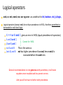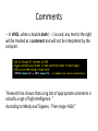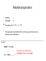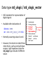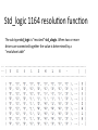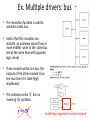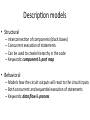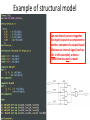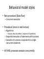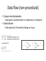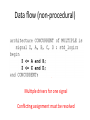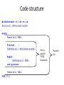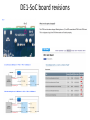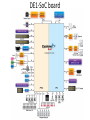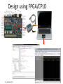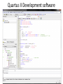
1
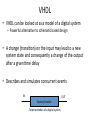
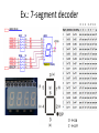
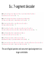
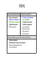
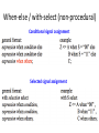
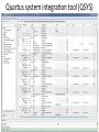
FYS4220 Real ,me and embedded data systems Introduc,on to Tools & VHDL Ke,l Røed Autumn 2015 Mo,va,on • Doing your first FPGA design. (Lab 1). • Some keywords for this lecture – En,ty & architecture – Signal declara,on & assignment – Descrip,on models (Structural, behavioral) • Component and port map • non-‐procedural and procedural (data-‐flow and process) (Some slides are based on material from 2011 lectures by J.K. Bekkeng) VHDL “It is well worth no-ng that VHDL and other similar hardware design languages are used to create most of the digital integrated circuits found in the various electronic gizmos that overwhelm our modern lives.” Mealy and Teppero, “Free range VHDL” VHDL • VHDL: VHISC Hardware Descrip,on Language – VHISC: Very High Speed Integrated Circuits • Introduced by the US Department of Defence (DoD) in 1981 • Ini,ally a specifica,on and modeling language -‐ documen,ng behavior of ASICs – Alterna,ve to complex manuals • The idea of simula,ng this documenta,on became aarac,ve and logic simulators where developed in the late 1980s. • The next step was the development of logic synthesis tools to read VHDL and output a defini,on of the physical implementa,on of the circuit • Today it is an industry standard (IEEE 1987) for specifying, verifying and designing digital electronics (library IEEE; use IEEE.std_logic_1164.all;) • Revised VHDL standards: VHDL 93, 2000, 2002, 2007, 2008 VHDL • VHDL can be looked at as a model of a digital system – Powerful alterna,ve to schema,c based design • A change (transi,on) on the input may lead to a new system state and consequently a change of the output aher a given ,me delay • Describes and simulates concurrent events IN System/module Representa,on of a digital system OUT Important remarks • VHDL is a HARDWARE DESCRIPTION LANGUAGE • You are designing actual hardware! • A VHDL model is translated into actual hardware and mapped onto a CPLD/FPGA • Due to the nature of hardware components which are always running, VHDL is a highly concurrent language. – Simultaneously execu,on of several tasks • This is in contrast to other high level languages where the code is executed (sequen,ally) by a processor (predefined hardware). • Execu,on of a VHDL code means that the VHDL model is being simulated (by sohware running on a computer) Design approach STUFF • VHDL descrip,ons of circuits are based on the black-‐box approach. • The two main parts of any hierarchical design are the black box and the stuff that goes into the black box (e.g. other black boxes) • In VHDL the black box is referred to as en#ty and the stuff that goes inside it is referred to as the architecture. • Allows to use hierarchical structure (modularity) and the reuse of previously wriaen code. • A module is referred to by its inherently simple black box representa,on rather than by the details of its inside circuitry Compared with an IC • The en#ty describes the interface to the outside world (connec,on pins of package) • The architecture describes the func,onality of the circuit inside the en,ty (package) En,ty & architecture templates entity model_name is port ( list of inputs and outputs ); end model_name; Same name as the file, e.g. module_name.vhd architecture architecture_name of model_name is begin ... VHDL concurrent statements .... end architecture_name ; En,ty declara,on • Abstract the func,onality of a circuit descrip,on to a higher level. • Provides a wrapper for the lower-‐level circuitry En,ty AND_GATE is A B Unique direc,on Iden,fier name Type of data Y Direc,on (mode) • In – flow into the en,ty • Buffer -‐ flow out of the en,ty, feedback allowed • Out – flow out of the • Inout -‐ for bi-‐direc,onal en,ty, no feedback signals Architecture • While en#ty describes the interface or external representa,on of the circuit, the architecture describes what the circuit actually does – Defines structure/behavior of the en,ty • En,ty declara,ons are generally easy while describing the opera,on of a circuit can become very complex En,ty AND_GATE is A Y Architecture B Y <= A and B Example of basic AND-‐gate En,ty AND_GATE is A Y Architecture B Y <= A and B A B Y Main VHDL object types • Signals – communica,on between components – Sohware representa,on of a wire (real physical signal) – Signal assignments are associated with a delay • Variables – Convenient mechanism for local storage – E.g. loop counters, intermediate values – All assignments take place immediately (no delay) • Constants – Is like a variable object but the value cannot change Declara,on and assignment • Needs to be declared before they are used • Declara,on of – Signals are done inside the scope of the architecture (cannot be declared inside a process) – Variables can only be done inside a process – Constants can be done in architecture and inside process • Assignment of a new value to a – Signal is done using the operator “<=" – Variable is done using the operator “:=” • Variable assignments are executed instantaneously while signal assignments are executed aher a certain ,me Iden,fier • Iden,fier is the name of an object (e.g. signal) • Names can be constructed using: – a b c … z (alphabe,c leaers) – 0 1 2 … 9 (numbers) – _ (underscore) • With the following reserva,ons: – – – – The first character must be a leaer The last character cannot be an under score Successive underscores are not allowed Cannot use VHDL reserved words (e.g. and, or, port, constant) • VHDL is case insensi,ve • nextstate ó NEXTSTATE ó nExTsTaTe Arithme,c & logical operators Arithme#c operators • + Addi,on • -‐ Subtrac,on • * Mul,plica,on • / Division Use with care, creates much logic Logical operators: • and, nand, or, nor, not, xor, xnor • IEEE 1164 uses these operators in std_logic Logical operators and, or, not, nand, nor, xor og xnor are predefined for bit, boolean, std_(u)logic, Logical operators (except not) do not have precedence in VHDL, therefore parenthesis is demanded in mul, level logic: X <= A or B and C gives an error in VHDL (equal precedence of operators) A or (B and C) Correct for VHDL (A or B) and C not A and B This is the same as: (not A) and B not has higher precedence than and, hence not A is evaluated before the and term. General recommenda,on is to be generous with parenthesis, it will make equa,ons more readable and less prone to errors. And you will not have to bother with precedence. Comments -‐-‐ In VHDL, when a double dash ( -‐-‐ ) is used, any text to the right will be treated as a comment and will not be interpreted by the compiler. “Research has shown that using lots of appropriate comments is actually a sign of high intelligence. “ According to Mealy and Teppero, “Free range VHDL” Rela,onal operators • equality • inequality = /= Size operators < , <= , > , >= • The operands must both be of the same type, and the result is a Boolean value (true/false) Example: signal a : std_logic; ………. if a = 1 then Gives an error, becasue a is std_logic, while 1 is an integer Data type std_ulogic / std_ulogic_vector • IEEE standards for representa,on of digital signals • Available aher declara,on of: • Normally assuming values 0 and 1 • However, the desire to model three-‐ state drivers, pull-‐up and pull-‐down outputs, high impedance state the std_ulogic type includes 9 different values ’U’ ’X’ ’0’ ’1’ ’Z’ ’W’ ’L’ ’H’ ’-‐’ Unini,alized Forcing Unknown Forcing 0 For synthesis Forcing 1 of logic High Impedance Weak unknown Weak 0 – pull down Weak 1 -‐-‐ pull up Don’t care Std_logic 1164 resolu,on func,on The sub type std_logic is ”resolved” std_ulogic. When two or more drivers are connected together the value is determined by a ”resolu,on table” Ex. Mul,ple drivers: bus • The resolu,on func,on is used to simulate a data bus. • Useful that the simulator can indicate an unknown value if two or more en,,es write to the same bus line at the same ,me with opposite logic values • If one module writes to a bus, the outputs of the other module’s bus line must be in tri-‐state (high impedance) • The unknown value ‘X’ has no meaning for synthesis. Conflic,ng assignment must be resolved Descrip,on models • Structural – Interconnec,on of components (black boxes) – Concurrent execu,on of statements – Can be used to create hierarchy in the code – Keywords: component & port map • Behavioral – Models how the circuit outputs will react to the circuit inputs – Both concurrent and sequen,al execu,on of statements – Keywords: data flow & process Example of structural model Can not directly connect together the input/output of a component to another component’s output/input! Must use an internal signal (such as int1 in this example), unless a connec#on to a port is made Behavioral model styles • Non-‐procedural (Data-‐flow) – Concurrent execu,on • Procedural (more in next lecture) – Algorithmic • step-‐by-‐step calcula,ons / sequence of opera,ons – Sequen,al execu,on of statements within process – Execu,on of a process is equivalent to a single concurrent statement. • All VHDL processes execute concurrently Data flow (non-‐procedural) • Concurrent statements – Executed in parallel (order or statements is irrelevant) • Event driven – Executed only if transi,on/change on input -----------------------B <= C; --executed if transition on C A <= B; --executed if transition on B is equivalent to A <= B; B <= C; ------------------------ C B A Data flow (non-‐procedural) Mul,ple drivers for one signal Conflic,ng assignment must be resolved Code structure Process parallelt VHDL kommando Parallell del Ex.: 7-‐segment decoder 0 1 2 3 4 5 6 (a) (f) (g) (e) (b) (c) (d) ‘0’ à ON ‘1’ à OFF Ex.: 7-‐segment decoder The use of logical operators and concurrent signal assignment is no longer comfortable. VDHL Non-procedural (data-flow) Procedural (sequential) • • • • • Process statement When else statement With select statement Signal declaration Block statement • • • • • • • • If- then- else statement Case statement Variable declaration Variable assignment Loop statement Return statement Null statement Wait statement Allowed in both non-procedural and procedural part • • • • Signal assignment Declaration of types and constants Function and procedure calls Assert statements When-‐else / with-‐select (non-‐procedural) Condi#onal signal assignment Selected signal assignment Ex. when – else: Tri-‐state buffer • The output buffer can be put into a high impedance (’Z’) state, such that only one en,ty writes to the bus • Three possible signal levels: ’0’, ’1’, ’Z’ • FPGAs and CPLDs have three-‐state buffers on the outputs (the signals defined as port in the en,ty) • However, many programmable logic devices can not have three-‐state buffers internally on the circuit (on internal signals) Data_bus data When – else Data_bus <= data when enable = '1' else (others => ‘Z’); enable Ex. when – else: Tri-‐state buffer Ex.: 7-‐segment decoder DE1-‐SoC board User Manual: DE1-‐SoC User Manual(rev.C/rev.D Board) TERASIC: DE1-‐SoC webpage DE1-‐SoC board revisions DE1-‐SoC board Design using FPGA/CPLD Ref: JKB slides 2011 Quartus II Development sohware Quartus system integra,on tool (QSYS) Development sohware • Quartus II Web Edi,on and Modelsim-‐Altera Starter Edi,on sohware can be downloaded for free from the Altera web page • Contains also QSYS and NIOSII EDS • Latest version is v15.0 (14.0 installed in lab.) QSYS: Quartus system integra,on tool EDS: Embedded Design suite General design flow steps • • Design entry – Register Transfer Level (RTL) descrip,on of design (schema,c or HDL) Synthesis – Checks code syntax, converts abstract form of desired circuit behavior into a design implementa,on of basic gate level primi,ves (netlist), i.e. circuit logic elements (gates, flip-‐flops, etc). A netlist is a text-‐based representa,on of a logic diagram. • Synthesis Translate – Merges netlist and constraints (e.g. physical port assignment, ,ming) into device specific design file. • Design Entry Map Translate Map – Fits the design into specific device resources (LUT, FF, RAM etc) • Place and route Place & route – Decides where in the die the resources will be placed and wires them together (accounts for ,ming constraints) • Generate configura,on bit file – That can be downloaded to the FPGA Generate configura,on bit file General simula,on steps • Behavioral simula,on – Simula,on to verify RTL behavioral code (no ,ming and resource informa,on) • Gate level func,onal simula,on – Run simula,on on gate level descrip,on generated by the synthesizer. – Can discover improper coding that works at RTL level but which violates synthesis coding conven,ons. Design Entry Behavioral Simula,on Synthesis Gate level func,onal simula,on Translate Map • E.g. omi•ng a signal in the sensi,vity list. Place & route • Gate level ,ming simula,on – Gate level simula,on with propaga,on delays Gate level ,ming Simula,on Generate configura,on bit file Sta,c Timing Analysis • Gate level ,ming simula,on of an en,re design can be slow and should be avoided. • In fact, not supported for Cylcone/Arria/Stra,x V devices. • Instead, use Sta,c Timing Analysis (STA) – method of compu,ng the expected ,ming of a digital circuit without requiring simula,on – Considers ,ming of paths from e.g. register to register, input port to register, register to output port, purely combina#onal paths. – No need for test vectors – However, does not check func,onality of design. => combine STA with behavioral simula,on (RTL). Design Entry Behavioral Simula,on Synthesis Gate level func,onal simula,on Translate Map Place & route Gate level ,ming STA Simula,on TimeQuest Timing Analyzer: hap://www.altera.com/literature/hb/qts/qts_qii53018.pdf Generate configura,on bit file How to simulate VHDL code • • • • Use a simula,on tool like e.g. ModelSim Test bench to apply s,muli/test inputs to the VHDL code Visual inspec,on through graphical output (waveform) Self-‐checking test benches (add code to check and verify result) Room V442, 4th floor of Physics building Please keep the lab. Clean and ,dy DE1-‐SoC boards