Transcript
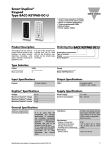
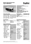
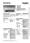
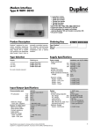
smart-house Keypad
BACC-KEYPAD-DC
smart-house keypad for building access control and alarm control
5 fixed addresses
Indoor or outdoor applications
GENERAL SPECIFICATIONS
Channel coding
Not possible – pre-coded to 5
fixed addresses, see channel
table below
Indications
3 LEDs, one yellow and two
dual colour red/green LEDs.
The behaviour of the three
LEDs is user configurable.
Built-in buzzer.
Environment
Degree of protection
Operating temperature
Storage temperature
Humidity (non condensing)
IP67
-15 – 60 C°
-30 – 80 C°
100%
Dimensions
Without frame 130 x 50 x 8 mm
Number of wires
4-wire cable, 8 m length
TYPE SELECTION
SUPPLY SPECIFICATIONS
Power supply
9-17 V DC
Current consumption
max. 100 mA
Ordering no.
BACC-KEYPAD-DC
Supplied with: two panel fronts, one
black and one white, and one white
frame
MODE OF OPERATION
Being equipped with 5 pre-defined addresses, the keypad can be used
to control more events in the building, e.g. alarm arming/disarming
including zone alarm, doorbell, switching of appliances etc.
The keypad is operated by the user by pressing the keys from 0-9, the
hash (#) and the bell ( ) symbol. Different codes can be selected for
different users, and codes can be added, modified and deleted.
The LED’s are used for indication of different signalling when the keypad is operated, and the red and green LED’s can also be controlled by
two Dupline addresses. By configuration change, the behaviour of the
LEDs can be set to other combinations. See the user manual for
overview.
The buzzer signals when a key is pressed, and gives also a signal whenever other keypad events occur, e.g. correct code entered, wrong code
entered etc. The buzzer can also be accessed by Dupline address B7.
DIMENSIONS
50
Configuration is also done by keying in new values on the keyboard,
either directly, or by first removing power to the unit (selectable).
Address
Function
B3
Output as a result of an operation of the bell key, or
code accepted 2 if multi-access control is selected
B4
Code accepted address, or code accepted 1 if
multi-access control is selected
B5
Address of the red LED (top middle)
B6
Address of the green LED (top right)
B7
Address of the buzzer
The user manual gives a complete setup of the keypad.
WIRING DIAGRAM
8
BACCKEYPAD-DC
Red=
Black=
Yellow=
Blue=
Power supply positive (+)
Power supply negative (-)
smart-house bus positive (D +)
smart-house bus negative (D -)
130
Red
Black
Yellow
Blue
Specifications are subject to change without notice (22.06.2009) - A product of the CARLO GAVAZZI Group