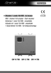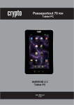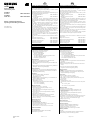
1
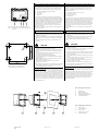
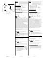
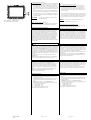
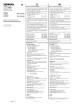
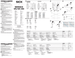
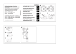
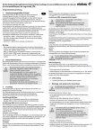
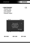
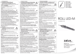
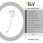
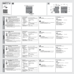
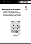
D
GAMMA instabus
Farb-Touch-Panel
Colour touch panel
UP 588/13
AC 230 V
UP 588/23
AC/DC 24 V
5WG1 588-2AB13
5WG1 588-2AB23
Bedien- und Montageanleitung
Operating and Mounting Instructions
Stand: März 2010
Issued: March 2010
Product- and Applications Description
The Colour touch panel UP 588 is a multi-functional display/control device for the KNX. The basis of the device is a 320
× 240 pixels TFT colour display with touch screen.
The colour depth is 263 K (R, G, B 6-bit), 218 colours. You operate the panel directly via the touch screen.
The display has LED background illumination, which you dim
with the user interface.
• UP 588/13 Colour touch panel
5WG1 588-2AB13
230V AC
• UP 588/23 Colour touch panel
5WG1 588-2AB23
24V AC/DC
In conjunction with the corresponding application program, the
display can be used to display and control up to 110 KNX functions of at least 20 control and display pages.
Time programmes with weekly schedules, a presence simulation feature and scenes can be programmed for these functions
or logic functions set up.
With a trend module status values can be display graphically
over the time.
Up to 16 active alarms can be indicated and acknowledged on a
alarm page or there is an option to use these activating conditions for 16 event tasks.
The panel has an internal real time clock and can therefore
function as the master timer in a KNX system.
Via the system settings one of four different design templates
can be selected for the display and operator interface.
Weitere Informationen
Additional Information
http://www.siemens.de/gamma
http://www.siemens.com/gamma
Technische Daten
Technical Specifications
Spannungsversorgungen
• Busspannung: erfolgt über die Buslinie
• Externe Spannungsversorgung für:
• Touch-Panel UP 588/13
230 V AC ±10%, 50/60 Hz
• Touch-Panel UP 588/23
18 - 36V DC, 400 mA, basisisoliert gegenüber 230 V
14 - 28V AC, 50/60 Hz, 400 mA,
basisisoliert gegenüber 230 V
Power supplies
• Bus voltage: via the bus line
• External power supply for:
• Colour Touch panel UP 588/13
230 V AC ±10%, 50/60 Hz
• Colour Touch panel UP 588/23
18 – 36 V DC, 400 mA, base isolated compared with 230 V
14 – 28 V AC, 50/60 Hz, 400 mA,
base isolated compared with 230 V
Bedienelemente
• Lerntaste zum Umschalten Normal- / Adressiermodus
• Reset-Taste zum Rücksetzen des Gerätes
• Resistiver Analog-Touch mit berührungssensitiver Fläche auf
dem Display
Operating elements
• Programming button to toggle between normal and addressing modes
• Reset button to reset the device
• Resistive analogue touch with contact-sensitive area on the
display
• Lebensdauer der Displayhintergrundbeleuchtung: 70000 Std.
(Helligkeit > 50 % der Originalhelligkeit)
Anzeigeelemente
• Programmier - LED rot zur Anzeige Normal/Adressiermodus
• Grafikfähiges TFT-Farbdisplay 320 x 240 Pixel (1/4 VGA) mit
LED-Hintergrundbeleuchtung
Anschlüsse
• Buslinie: Busklemme KNX, schraubenlos
0,6 ... 0,8 mm ∅ eindrähtig
Abisolierlänge 5 mm
• USB-Buchse Mini Typ B (Verwendung nur im Bedarfsfall, zum
Laden der Bilder und Symbole)
• Spannungsversorgung
Abisolierlänge: 6...7 mm
Es sind folgende Leiter/Leiterquerschnitte zulässig:
- 0,5...2,5 mm2 eindrähtig
- 0,5...1,5 mm2 feindrähtig
Mechanische Daten
• Gehäuse Touch Panel: Kunststoff
• Aussenabmessungen Displaymodul (B x H x T):
157 x 131 x 60 mm
• Aussenabmessungen der Designrahmen (B x H x T):
194 x 156 x 5 mm
• Aussenabmessungen des Passepartoutrahmen (B x H):
152 x 123 mm
• Einbautiefe in UP-Dose: 64 mm
• Montage: wird in zugehörige UP-Dose eingeschraubt
• Abmessungen zugehörige UP-Dose (BxHxT):
161,5 x 135 x 64 mm , nicht im Lieferumfang enthalten
• Gewicht: ca. 510 g
EMV-Anforderungen
Erfüllt EN 50090-2-2
Umweltbedingungen
• Klimabeständigkeit: EN 50090-2-2
• Umgebungsbedingungen im Betrieb: 0°C bis +45°C
• Lagertemperatur: -25°C bis +70°C
• Rel. Feuchte (nicht kondensierend): 5 % bis 93 %
Prüfzeichen KNX/EIB
CE-Kennzeichnung
Gemäss EMV-Richtlinie (Wohn- und Zweckbau),
Niederspannungsrichtlinie
A5E02834306C
DS01
GB
Produkt- und Funktionsbeschreibung
Das Farb-Touch-Panel UP 588 ist ein multifunktionales Anzeige-/
Bediengerät für den KNX-Bus. Basis des Gerätes ist ein 320 x
240 Pixel TFT-Farbdisplay mit Touchscreen.
Die Farbtiefe beträgt 263 K (R,G,B 6Bit), 218 Farben. Bedient
wird das Panel direkt über den Touchscreen.
Das Display verfügt über eine LED-Hintergrundbeleuchtung, die
über die Bedienoberfläche dimmbar ist.
• Touch-Panel UP 588/13
5WG1 588-2AB13
AC 230V
• Touch-Panel UP 588/23
5WG1 588-2AB23
AC / DC 24V
In Verbindung mit dem zugehörigen Applikationsprogramm
kann das Display zur Darstellung und Bedienung, von bis zu 110
KNX-Funktionen auf 20 Bedien- und Anzeigeseiten, eingesetzt
werden.
Für diese Funktionen können Zeitprogramme mit Wochenschaltplänen, eine Anwesenheitssimulation, Szenen programmiert oder Logikfunktionen parametriert werden.
Mit einem Trendmodul können Statuswerte über die Zeit grafisch dargestellt werden.
Auf einer Alarmseite können bis zu 16 eintreffende Alarme angezeigt und quittiert werden oder es besteht die Möglichkeit
diese Auslösebedingungen für 16 Ereignisaufträge zu nutzen.
Das Panel besitzt eine interne Echtzeituhr und kann damit als
Zeitmaster in einem KNX-System fungieren.
Über die Systemeinstellung kann eine von vier unterschiedlichen Designvorlagen zur Bedien- und Anzeigeoberfläche gewählt werden.
Für das Touch-Panel ist folgende Auswahl als Zubehör erforderlich:
Designrahmen Aluminium
5WG1 588-8AB12
Designrahmen Edelstahl Design
5WG1 588-8AB13
Designrahmen Glas schwarz
5WG1 588-8AB14
Designrahmen Glas weiss
5WG1 588-8AB15
Einbau-/Hohlwanddose
5WG1 588-8EB01
Seite 1 von 4
The following choice as accessories is needed for the colour
touch panel:
Desig frame aluminium
5WG1 588-8AB12
Design frame stainless steel design
5WG1 588-8AB13
Design frame glass black
5WG1 588-8AB14
Design frame glass white
5WG1 588-8AB15
Relevant flush-type box
5WG1 588-8EB01
• Life time of the display backlight: 70000 h
(brightness > 50 % the original brightness)
Display elements
• Red programming LED for displaying normal/addressing
mode
• Graphics-capable TFT colour display 320 × 240 pixels (1/4
VGA) with LED background lighting
Connections
• Bus line: KNX bus terminal, screwless
0.6... 0.8 mm ∅ solid, stripped length 5 mm.
• USB socket mini type B (use only if needed for image and
symbols load)
• Power supply
stripped length: 6...7 mm
The following conductor/conductor cross-sections are permitted:
- 0.5...2.5 mm2 solid
- 0.5..0.1.5 mm2 finely-stranded
Mechanical data
• Housing: Touch panel: plastic
• Outer dimensions of the display modul (W x H x D):
157 x 131 x 60 mm
• Outer dimensions of the design frame (W × H × D):
194 × 156 × 5 mm
• Outer dimensions of the passepartout blind (W × H):
152 × 123 mm
• Mounting depth in flash-type box: 64 mm
• Installation: is screwed into the corresponding flush-type box
• Dimensions of corresponding flush-type box (W × H × D):
161.5 × 135 × 64 mm, not included with supply
• Weight: approx. 510 g
EMC requirements
Complies with EN 50090-2-2
Ambient conditions
• Climatic withstand capability: EN 50090-2-2
• Ambient operating conditions: 0°C to +45°C
• Storage temperature: -25°C to +70°C
• Relative humidity (non-condensing): 5% to 93%
Markings KNX/EIB
CE-mark
In accordance with the EMC guideline (residential and functional buildings) and the low voltage guideline
Page 1 of 4
Lage- und Funktion der Anzeige- und Bedienelemente
Location and Function of the Display and Operating Elements
Die Geräteanschlüsse, sowie die bei der Inbetriebnahme benötigten Elemente Lerntaste und Programmier-LED sind auf der
Geräterückseite zugänglich. Bild 1 zeigt die Geräterückseite
The device connections as well as the programming button and
programming LED which are required for the commissioning
stage are accessible at the back of the device. Figure 1 shows
the back of the device.
A
B
C
D
A
B
C
D
Bild 1: Lage der Anschluss- und Bedienelemente
Figure 1: Location of the connection and operating
elements
Anschlussklemme 230 V bzw. 24 V AC/DC
Programmier - LED
Lern - Taste
Busklemme
Connection terminal 230 V or 24 V DC
Programming LED
Programming button
Bus terminal
Der Anschluss der Busleitung erfolgt über eine Standardbusklemme, die in die entsprechende Klemmenaufnahme auf der
rechten Gehäuseseite eingesteckt ist D. Links neben dem Steckplatz für die Busklemme befinden sich die Lern-Taste C und die
Programmier-LED B. Die Anschlussklemme für die 230 V Netzversorgung oder bei der 24 V Variante für die 24 V AC/DC Versorgung befindet sich auf der linken Geräteseite A. Zum Anschluss der Spannungsversorgungsleitung muss die Klemme
abgezogen werden.
Die auf dem Gehäuse gekennzeichnete Anschlussfolge ist unbedingt zu beachten!
The bus cable is connected via a standard bus terminal D, which
is plugged into the corresponding terminal slot on the right side
of the housing. On the left, beside the plug-in slot for the bus
terminal are the programming button C and the programming
LED B. The connection terminal for the 230 V power supply or,
in the 24 V version for 24 V AC/DC supply are on the left side A
of the device. The terminal must be removed to connect the
power supply.
It is essential to obey the connection sequence marked on the
housing!
Montage und Verdrahtung
Mounting and Wiring
Installationshinweise
• Das Gerät ist für feste Installation in Innenräumen, für trockene Räume, vorgesehen
• Zum Einbau der Montagedose ist ein Mauer- oder Hohlwandausbruch von 161,5 x 135 x 64 mm erforderlich (siehe Bild
2).
• Die Einbautiefe des Ausbruches muss mindestens 64 mm
betragen
Installation directions
• The device is designed for fixed installation in interior rooms,
for dry rooms.
• To install the assembly socket, a wall or hollow wall outbreak
of 161.5 x 135. x 64 mm is required (see figure 2).
• The installation depth of the outbreak must be at least 64
mm.
V
Bild 2: Bohrskizze für Holwanddose
Figure 2: Drilling jig for cavity wall box
A
B
C
D
V
GEFAHR
• Das Gerät darf nur von einer zugelassenen Elektrofachkraft
installiert und in Betrieb genommen werden.
• Das Gerät darf nur in Verbindung mit den genannten Zubehörteilen, insbesondere der genannten UP-Dose eingesetzt
werden.
• Innerhalb der UP-Dose dürfen keine 230V Geräte, die nicht
zum Lieferumfang gehören, eingesetzt,
oder 230V Leitungen durchgeschleift werden!
• Die geltenden Sicherheits- und Unfallverhütungsvorschriften
sind zu beachten.
• Die Netzspannung darf erst zugeschaltet werden, wenn das
Gerät vollständig montiert ist.
• Auf sichere Trennung zwischen Busleitung und 230VVersorgung ist zu achten.
• Bei der Planung und Errichtung von elektrischen Anlagen sind
die einschlägigen Richtlinien, Vorschriften und Bestimmungen des jeweiligen Landes zu beachten.
Allgemeine Beschreibung
Die Gerätemontage 2 darf nur in die, als Zubehör zu bestellende, Einbaudose 1 erfolgen. Bei der Leitungseinführung in die
Einbaudose ist zu beachten, dass die Busleitung in den linken
unteren Ausbruch eingeführt wird und die Spannungsversorgungsleitung in den rechten Ausbruch eingeführt wird. Bus und
Spannungsversorgungsleitung dürfen nicht gemeinsam durch
einen Ausbruch in die Einbaudose eingeführt werden. Innerhalb
der Dose ist die Leitung so zu führen, dass ein minimaler Abstand von 10 mm zwischen Bus und Spannungsversorgungsleitung gewährleistet ist.
DANGER
• The device may only be installed and commissioned by an
authorised electrician.
• The device may only be used in connection with the named
accessories, in particular the flush-type box.
• 230V devices which are not included with supply may not be
inserted in the flush-type box. It is also not possible to loop
through 230V cables.
• The prevailing safety and accident regulations should be observed.
• The power supply voltage may only be connected to the supply if the device has been fully installed.
• Protective isolation should be ensured between the bus cable and the 230V power supply.
• For planning and construction of electric installations, the
relevant guidelines, regulations and standards of the respective country are to be considered.
General description
The device 2 may only be mounted in the flush-type box 1, to
be ordered as an accessory. When the cable is brought into the
flush-type box, take care that the bus cable is fed in through the
bottom left hand recess and the power supply cable is fed in
through the right hand recess. The bus and power supply cables
must not be fed into the flush-type box through the same recess. Inside the box, the cable is to be routed so that there is a
guaranteed separation of at least 10 mm between bus and
power supply cables.
Bild 3: Montage des Touch Panels
1
2
3
4
5
Einbaudose
Farb Touch Panel
Befestigungsschrauben
verschiedene Designrahmen
Passepartoutrahmen
Figure 3: Mounting the touch panel
1
A5E02834306C
DS01
2
3
4
Seite 2 von 4
5
1
2
3
4
5
Flush-type box
Colour touch panel
Fixing screws
different design frames
Passepartout blind
Page 2 of 4
Achtung:
Der Passepartoutrahmen ist asymmetrisch
und kann nur in entsprechender Richtung auf
das Panel gerastet werden. Bei falscher Ausrichtung des Passepartoutrahmens ist der
grüne Displayrand zu sehen. In diesem Fall
ist der Passepartoutrahmen um 180° zu drehen.
C3
C3.1
C3.3
C3.2
Anschließen der Busleitung (Bild 4 “A“)
C3.4
− Die Busklemme (C3) ist für eindrähtige Leiter mit
0,6 ... 0,8 mm Ø geeignet.
− Den Mantel der Busleiter ca. 3cm abisolieren
− Die Leiter (C3.4) ca. 5 mm abisolieren und in Klemme
(C3) stecken (rot = +, grau = -).
C3
C4.2
5 mm
C4
C3.4
C3
6....7mm
"A"
Bild 4: Anschlüsse
Figure 4: Connections
C4.1
"B"
Notice:
The passepartout blind is asymetric such that it
can only be mounted on the panel in a defined
orientation. If the passepartout blind is
mounted with false orientation the green edge
of the display is visible. In this case the
passepartout blind has to be turned by 180°.
Connecting the bus cable (figure 4 "A")
− The bus terminal (C3) is suitable for solid conductors with
a diameter of 0.6 ... 0.8 mm.
− Strip off approx. 3 cm of the bus cable insulation
− Strip the insulation from the conductors (C3.4) to a distance of approx. 5 mm and plug it into the terminal (C3)
(red = +, grey = -).
Busklemme aufstecken (Bild 4 „A“)
− Die Busklemme in die Führungsnut stecken und
die Busklemme (C3) bis zum Anschlag nach unten drücken
Clipping on bus terminal (figure 4)
− Plug the bus terminal into the guide slot and press it (C3)
downwards to the end stop
Spannungsversorgung anschließen (Bild 4 “B“)
− Die Leiter (C4.1) 6...7 mm abisolieren, in die Spannungsversorgungsanschlussklemmen (C4) stecken und die
Schrauben (C4.2) anziehen.
Connecting the power supply (Figure 4 "B")
− Strip the insulation from the conductor (C4.1) to a distance of 6...7 mm, plug it into the power supply connection terminals (C4) and tighten the screws (C4.2).
Klemmenbelegung:
Terminal assignment:
230V
1
2
3
Erde
N
L
Neutralleiter
Phase
+/- DC: AC
1
230V
Earth
nicht belegt
In2: +/- DC: AC
2
3
N
L
24V
In1:
Nach dem Anschluss der Busklemme und der Spannungsversorgungsanschlussklemme an die Leitungen werden die Klemmen
in die entsprechenden Steckerauslässe am Touch-Panel eingesteckt. Die Netzspannung darf erst zugeschaltet werden, wenn
der Anschlussstecker fest in das Gerät eingerastet ist. Nach dem
Anlegen der Busspannung und der Spannungsversorgung kann
die Lerntaste gedrückt und die physikalische Geräteadresse programmiert werden. Nach dem Programmieren der physikalischen Adresse muss die LED erloschen sein.
Dann wird das Gerät mit den vier beiliegenden Schrauben 3 in
die Einbaudose eingeschraubt (siehe Bild 3).
Die über der Displayoberfläche angebrachte Schutzfolie darf
jetzt abgezogen werden. Zu diesem Zweck dürfen keine scharfen Gegenstände oder Werkzeuge benutzt werden.
Nach dem Verschrauben des Displaymoduls und dem Entfernen
der Schutzfolie kann der gewünschte Designrahmen 4 auf das
Gerät aufgesteckt werden. Dabei ist die Montagerichtung des
Designrahmens zu beachten. Schließlich wird der Passepartoutrahmen 5 auf das Display aufgesteckt und eingerastet und dadurch der Designrahmen gehalten. Auch bei der Montage des
Passepartoutrahmens ist die Montagerichtung zu beachten. Sie
ist so aufzustecken, dass sämtliche Elemente des Displayrahmens vollständig abgedeckt sind.
V
Neutral conductor
Phase
Keinen direkten Druck auf das
Display ausüben!
Nach Abschuss der Montage kann das Gerät in Betrieb genommen werden (Programmierung siehe Applikationsprogrammbeschreibung).
Bitte Beachten Sie, dass der Geräteanlauf erst nach Zuschalten
der Spannungsversorgung und der Busspannung erfolgt und bis
zu 1 Minute dauern kann.
± DC: AC
not connected
In2: ± DC: AC
After connecting the bus terminal and the power supply to the
conductors, the terminals are plugged into the corresponding
outlets on the touch panel. The power supply must only be
switched on when the plug is engaged firmly in the device. After switching on the bus voltage and the power supply, the programming button can be pressed and the physical device address programmed. The LED must go out after programming
the physical address.
The device is then screwed into the flush-type box with the four
screws 3 enclosed (see figure 3).
The protective film applied to the display surface can now be
removed. Do not use any sharp items or tools to do this.
After the screwing the display modul and the removal of the
protective film, the design frame 4 can be plugged into the device. At the same time, take note of the direction for mounting
the frame. Finally, the passepartout blind 5 are plugged on to
the display and thus held by the frame. The mounting direction
must also be observed when mounting the passepartout blind.
It is to be plugged in such that all elements of the display
frame are covered completely.
V Caution
Vorsicht:
24V
In1:
:
Do not press directly on the display!
After mounting is completed, the device can be used (for programming, see the application program description).
Please note the device can only be started after the power supply and the bus voltage have been switched on and this may
take up to 1 minute.
Dismantling / exchanging the design frame
Demontage / Austausch des Designrahmens
- Zuerst Spannungsversorgung abschalten
- Zur Gerätedemontage oder zum Austausch des Designrahmens
ist zunächst der Passepartoutrahmen zu entfernen.
V
Vorsicht:
Nach dem Entfernen des Passepartoutrahmens kann der Designrahmen ausgetauscht werden oder das Gerät vollständig
demontiert werden.
Spannungsversorgungsanschluss abklemmen (Bild 4 “B“)
A5E02834306C
DS01
V Caution
:
Do not press directly on the display!
Keinen direkten Druck auf das Display
ausüben!
-
- First of all switch off the power supply
- The passepartout blind must be removed initially to dismount
the device or exchange the frame.
Zur Demontage der Spannungsversorgungsanschlussklemme C4 muss diese über die Rastung hinweg nach
unten aus dem Klemmraum abgezogen werden. Das Abziehen kann durch leichtes Anheben der Spannungsversorgungsanschlussklemme C4 mit Hilfe eines schmalen
Schlitzschraubendrehers erleichtert werden. Er wird hierzu in der Mitte der Klemmenrastung zwischen Spannungsversorgungsanschlussklemme C4 und Klemmraumboden eingeführt.
Seite 3 von 4
After removing the passepartout blind, the design frame can be
exchanged or the device dismounted completely.
Disconnecting the power supply (figure 4 "B")
-
To dismount the power supply terminal (C4), this must be
pulled downwards over the detente and out of the slot.
The removal can be made easier by lifting the power supply connection terminal (C4) slightly with a flat-bladed
screwdriver. To do this, push the blade of the screwdriver
into the centre of the terminal detente between the power supply connection terminal (C4) and the base of the
slot.
Page 3 of 4
F
E
Busklemme abziehen (Bild 4 “A“)
- Die Busklemme (C3) befindet sich im linken Klemmenanschlussraum. Sie besteht aus zwei Teilen (C3.2 und C3.3) mit
je vier Klemmkontakten. Es ist darauf zu achten, dass die beiden Prüfbuchsen (C3.1) weder mit dem Busleiter (versehentlicher Steckversuch), noch mit dem Schraubendreher (z.B.
beim Versuch, die Busklemme zu entfernen) beschädigt werden.
- Den Schraubendreher vorsichtig in den Drahteinführungsschlitz des grauen Teils der Busklemme (C3.3) einführen und
die Busklemme (C3) aus dem Einbaugerät herausziehen.
Beim Herausziehen des roten Teils der Busklemme bleibt der
graue Teil stecken.
Achtung:
Bild 5: Resettaste und USB-Anschluss
Figure 5: reset button and USB port
Busklemme nicht von unten heraushebeln!
Kurzschlussgefahr!
Abklemmen der Busleitung (Bild 4 “A“)
Die Busklemme (C3) abziehen und den Leiter (C3.4) der Busleitung, bei gleichzeitigem Hin- und Herdrehen, herausziehen.
Removing the bus terminal (figure 4 "A")
- The bus terminal (C3) is in the left slot. It consists of two
parts (C3.2 and C3.3), each with four terminal contacts. You
must take care that both test sockets (C3.1) are not damaged, either with the bus conductor (accidental attempt to
plug in) or with the screwdriver (e.g. when trying to remove
the bus terminal).
-
Push the screwdriver carefully into the wire connection slot
of the grey part of the bus terminal (C3.3) and then pull the
bus terminal (C3) out of the device. When pulling out the red
part of the bus terminal, the grey part remains plugged in.
Notice:
Do not lever the bus terminal outwards from
below! Danger of short circuit!
Disconnecting the bus terminal (figure 4 "A")
Pull off the bus terminal (C3) and pull out its conductor (C3.4)
by turning it alternately backwards and forwards.
Rücksetzen des Gerätes im Fehlerfall
Resetting the device if there is an error
Das Touch-Panel kann über eine Resettaste im Fehlerfall zurückgesetzt werden. Die Resettaste F (siehe Bild 5) ist zugänglich
nach der Demontage des Designrahmens (s.o.). Sie kann mit einem Werkzeug bedient werden. Sollte in seltenen Einzelfällen
aufgrund einer Störung in der Software oder während eines Ladevorgangs die Funktion des Displays nicht mehr gegeben sein,
betätigen Sie bitte kurzzeitig die Resettaste. Danach läuft das
Gerät innerhalb einiger Sekunden erneut an und der Designrahmen kann wie oben beschrieben wieder montiert werden.
Erfolgt trotz des Resets kein Geräteanlauf, kontaktieren Sie bitte
den Hersteller.
Erweiterte Programmierung über frontseitigen USBAnschluß
Extended programming via the front USB port
Das Übertragen von kundenspezifischen Bildern und Symbolen
(siehe dazu das Benutzerhandbuch) erfolgt über die frontseitige
Mini-USB-Buchse E (siehe Bild 5). Nach der Demontage des Designrahmens (s.o.) ist die USB-Buchse zugänglich. Bitte verbinden Sie über ein USB-Kabel mit Typ B Mini-USB-Steckverbinder
das Display mit einem beliebigen PC mit USB-Schnittstelle Typ A.
Das USB-Kabel gehört zum Lieferumfang und liegt dem TouchPanel bei.
Es hat eine Länge von 1 m und besitzt eine Transferrate von
480 MBit/sec.
Nach Abschluss der Übertragung entfernen Sie bitte das Kabel
und montieren den Designrahmen wie oben beschrieben.
Pictures and symbols to order (see the user manual for this) are
transferred via the front mini-USB socket E (see figure 5). The
USB socket is accessible after dismounting the design frame
(see above). Connect the display to any PC with a USB interface
type A via a USB cable with a type B mini-USB plug.
The USB cable is part of the shipment and is enclosed in the
touch panel.
It has a length of 1 m and have a transfer rate of 480 MBit/sec.
After completing the transfer, remove the cable and mount the
design frame as described above.
Pfegehinweise
Care instructions
Die Reinigung des Designrahmens und der Kunststoffoberfläche des Displays kann mit handelsüblichen, lösungsmittelfreien Reinigungsmitteln erfolgen. Die Displayoberfläche
selbst darf nur mit einem feuchten, weichen Tuch (z.B. Brillenputztuch) und ggf. einem milden Glasreiniger gesäubert werden.
Bitte keine mechanischen Hilfsmittel (rauher Schwamm oder
Ähnliches) zur Reinigung einsetzen. Die TouchscreenOberfläche ist kratzempfindlich.
The display's design frame and plastic surface can be cleaned
with off-the-shelf, solvent-free cleaning agents. The display surface itself should be cleaned with a soft, damp cloth (e.g. spectacles cloth) and, if necessary, a mild glass cleaner.
Do not use any mechanical aids (rough sponge or similar materials) for cleaning. The touch screen surface is easy to scratch.
General notes
Allgemeine Hinweise
• Ein defektes Gerät ist an die zuständige Geschäftsstelle der
Siemens AG zu senden.
• Ein defektes Gerät ist mit einem Rücklieferschein der zuständigen Vertriebsniederlassung an folgende Adresse zu senden:
SIEMENS AG, Siemensstr. 10, D-93055 Regensburg
• Bei zusätzlichen Fragen zum Produkt wenden Sie sich bitte
an unseren Technical Support:
+49 (911) 895 - 7222
+49 (911) 895 - 7223
[email protected]
http://support.automation.siemens.com
A5E02834306C
DS01
You reset the touch panel in the event of an error with the reset
button. The reset button F (see figure 5) is accessible after dismounting the design frame (see above). This is done with the
special tool. Should the display fail in rare cases owing to a
fault in the software or during the loading process, tap the reset
button. The device then restarts within a few seconds and the
design frame can be remounted as described above. If the device will not start, despite a reset, contact the manufacturer.
Seite 4 von 4
• Any faulty device should be returned to the local Siemens office.
• A faulty device shall be sent with a Return Good Note for Service provided by the appropriate Siemens sales office to the
following address:
SIEMENS AG, Siemensstr. 10, D-93055 Regensburg
• If you have further questions concerning the product, please
contact our Technical Support:
+49 (0911) 895 - 7222
+49 (0911) 895 - 7223
[email protected]
http://support.automation.siemens.com
Page 4 of 4