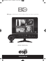
1
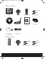
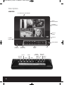
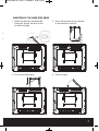
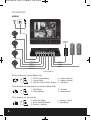
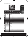
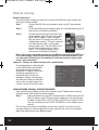
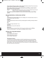
BDEye Manual_Layout 2 21/08/2012 12:05 Page 1
BDeye combined CCTV video door access system
U S E R M ANUAL
BDEye Manual_Layout 2 21/08/2012 12:06 Page 2
2
BDEye Manual_Layout 2 21/08/2012 12:06 Page 3
Contents
Whats included . . . . . . . . . . . . . . . . . . . . . . . . . . . . . . . . . . . . . . . . . . . . . . . . . . . . 5
Monitor description . . . . . . . . . . . . . . . . . . . . . . . . . . . . . . . . . . . . . . . . . . . . . . . . . 6
Insertion of the hard disk drive . . . . . . . . . . . . . . . . . . . . . . . . . . . . . . . . . . . . . . 7
Installation . . . . . . . . . . . . . . . . . . . . . . . . . . . . . . . . . . . . . . . . . . . . . . . . . . . . . . . . 8
Operation buttons . . . . . . . . . . . . . . . . . . . . . . . . . . . . . . . . . . . . . . . . . . . . . . . . . . 9
Basic operations . . . . . . . . . . . . . . . . . . . . . . . . . . . . . . . . . . . . . . . . . . . . . . . . . . . 10
Controls . . . . . . . . . . . . . . . . . . . . . . . . . . . . . . . . . . . . . . . . . . . . . . . . . . . . . . . . . . 10
Making a recording . . . . . . . . . . . . . . . . . . . . . . . . . . . . . . . . . . . . . . . . . . . . . . . . 11
Playing back a recording . . . . . . . . . . . . . . . . . . . . . . . . . . . . . . . . . . . . . . . . . . . 11
Transferring a recording to USB . . . . . . . . . . . . . . . . . . . . . . . . . . . . . . . . . . . . . 12
Alarm input and output . . . . . . . . . . . . . . . . . . . . . . . . . . . . . . . . . . . . . . . . . . . . 12
System . . . . . . . . . . . . . . . . . . . . . . . . . . . . . . . . . . . . . . . . . . . . . . . . . . . . . . . . . . . 13
Remote viewing . . . . . . . . . . . . . . . . . . . . . . . . . . . . . . . . . . . . . . . . . . . . . . . . . . . 14
Trouble shooting . . . . . . . . . . . . . . . . . . . . . . . . . . . . . . . . . . . . . . . . . . . . . . . . . . 17
Technical specification . . . . . . . . . . . . . . . . . . . . . . . . . . . . . . . . . . . . . . . . . . . . 19
This manual is designed to be used as a quick start guide alongside the informative
general user interface (GUI) of the DVR. Additional details of the subjects covered
may be found within the on-screen menus of the machine itself. The menu above is
not exhaustive and is designed to lead the user quickly to the most often required
aspects of the unit.
3
BDEye Manual_Layout 2 21/08/2012 12:06 Page 4
SAFETY NOTICE
IMPORTANT PRECAUTIONS!
HIGH VOLTAGE HAZARD!
HIGH VOLTAGE INSIDE!
• Please keep this manual for later use.
• Please strictly comply with the warning indications on the machine and in this
book.
• Please abide by instructions when operating.
• Do not use accessory devices not recommended by the manufacturer. Incorrect
usage of accessory device may cause harm.
• Please use the power adapter equipped for the unit. Before connecting the AC
power cord to the socket, please check if the specified requirements of the
adapter is in accordance with the local power supply network. Please contact
your dealer or the local power supply administration if you are not sure about
the power supply to be used.
• Do not place anything on or around the power cord. A damaged power cord may
cause electric shock.
• Please do not touch any control parts not mentioned in the manual. Incorrect
adjustment of a control part not mentioned in the manual may damage the
machine.
• Before cleaning the machine, pull out the power plug and clean the machine
with a slightly damp cloth. Do not use any liquid or sprayed cleaning agent.
• Disconnect the unit from the mains power source if the unit is not likely to be
used for a long period of time.
• Ensure air ventilation around the unit, and do not cover or block the vent hole
• Do not place the unit in direct sunlight or near a heat source such as a heat
radiator, heating equipment, or other objects that generate heat.
4
BDEye Manual_Layout 2 21/08/2012 12:06 Page 5
What is included
Monitor
Camera
Remote Controller
15m Camera Cable
Software
500GB Hard Drive
User Manual
USB Mouse
4 x DIN to
BNC adaptor cables
USB Memory Stick
Camera Extension Cable
VDE Extension Cable
Optional Extras
VDE Call Point
Camera
5
BDEye Manual_Layout 2 21/08/2012 12:06 Page 6
Description
MONITOR
2.5" HARD DISK CARTRIDGE
VOICE
ADJUSTMENT
VOLUME
ADJUSTMENT
USB X 2
PORTS
A/V OUT
POWER
SWITCH
IR RECEIVER
LOUD
SPEAKER
POWER
INDICATOR
CAM 4
SENSOR
DEVICE
6
TOUCH
PANEL
CAM 2
CAM 3
CAM 1
MIC
TCP/IP
NETWORK
VDE CALL
POINT 2
VDE CALL
POINT 1
POWER
SUPPLY
BDEye Manual_Layout 2 21/08/2012 12:06 Page 7
INSERTION OF THE HARD DISK DRIVE
1. Follow the direction marked beside
the button to open the cover of the
hard disk cartridge.
2. Insert the hard disk paying attention
to the direction of the slot.
3. Push the hard disk down.
4. Close the cover.
T
T
R
7
BDEye Manual_Layout 2 21/08/2012 12:06 Page 8
Installation
WIRING
POWER
SUPPLY
TCP/IP (Network)
6-Pin connector for camera (BDeye Cam)
1
2
3
6
5
4
1 – GND for Video (Black)
6 – Audio In (White)
2 – Control (Blue)
5 – Video In (Yellow)
3 – GND for Audio & Power (Brown) 4 – VDD (Red)
4-Pin connector for video door entry call point (BDeye VDE)
1
4
2
3
1 – GND (Black)
2 – Video (Yellow)
3 – B+ (Red)
4 – Audio (White)
5-Pin connector for alarm device
5
1
2
8
4
3
1 - Alarm Out (Blue)
2 - Alarm Out/GND (Brown)
3 - Alarm In 1 (White)
4 - Alarm In 2 (Red)
5 - GND (Black)
BDEye Manual_Layout 2 21/08/2012 12:06 Page 9
Operation buttons
ICON
NAME
Display
Full Screen Display of Channel 1/Number 1
Display
Full Screen Display of Channel 3/Number 3
Display
Display
Display
PTZ
OPERATION
Setup
PTZ Setup
Full Screen Display of Channel 2/Number 2
Full Screen Display of Channel 4/Number 4
Quad Display
Enter/Exit Setup
PTZ Setup
REC
Start/Stop Recording
Play
Play/Pause
Stop
Stop
Move/Confirm
Up
Move/Confirm
Left/Backward
Move/Confirm
Move/Confirm
Move/Confirm
Talk/Monitoring
Unlock
Display On/Off
Down
Right/Forward
Choose/Confirm
Talk/Monitoring/Turn on Monitor Display
Unlock
Turn On/Off Monitor Display
Note: Buttons on the remote controller are same functions as on monitor buttons, except
the
(On/Off) on the remote controller.
9
BDEye Manual_Layout 2 21/08/2012 12:06 Page 10
Operation
HOW TO TURN ON
1. Push the power switch on the left side of the indoor unit, the monitor will start.
2. The monitor shows quad monitoring at start up after system check.
MOUSE CONNECTION
In order to prevent un-authorised tampering most functions of the DVR are mouse
controlled . Please plug in the supplied mouse via the USB interface on the right hand
side of the monitor.
LIVE VIEWING
On start up the monitor will display a quad (four channel) image. Using Mouse double
click on any image to bring to full screen. Double click again to return to a quad screen.
System time and date, channel name, recording status and alarm status are indicated
by the following icons:
Recording status
Video loss
Motion detect
Camera lock
Controls
Right click the mouse anywhere on screen to activate the control menu selections.
Selecting main menu will automatically show the SYSTEM LOGIN screen. The default
settings are
User Name: Admin
Password:
leave blank
Once logged in you may now right click again to access your menu selections. An
opportunity to change the password is provided within the settings menu. Please note
if an incorrect password is entered three times the monitor alarm will activate. If a
wrong password is entered five times the system will lock out. To reset the system turn
the main power off and back on after 5 minutes.
SHORTCUT MENU
Selecting main menu will take you through to the shortcut menu where most regularly
used settings can be found. Explanations of functions are displayed by hovering the
mouse over each icon.
Record
Record set up / record playback / record back up
Alarm
Motion detection and alarm event settings
System
Time and date / network settings / on-screen display settings
Advanced
Hard disk management / password settings / network settings
Info
Hard Drive status / system usage log / version details
10
BDEye Manual_Layout 2 21/08/2012 12:06 Page 11
Making a recording
RECORD CONFIGURATION
This section allows you to configure the recording capability of the DVR to your precise
requirements by each channel / camera.
Channel
Select 1–4 (all other settings now effect the specific channel selected)
Redundancy Select if double ( backup ) recording is required when two hard drives are
fitted
Length
The record time captured when using motion or alarm trigger detection
Pre-Record The system can automatically archive up to 30 seconds of recording prior
to a motion or alarm trigger
Mode
Selects the recording preference either by schedule or to stop and start
recording manually
SCHEDULE RECORDING
Week
You now have the ability to specify the recording requirements by each
day ( select all if all days are the same )
Period 1-4
Each day can be segmented into 4 specific recording periods
Regular
Simply records constantly within the selected period
Detect
Only records by motion detection within the selected period
Alarm
Only records by alarm trigger within the selected period
PLAYING BACK A RECORDING
To view recorded data right click anywhere on screen and enter playback directly from
the menu. The playback screen can also be found in the main menu shortcuts record >
Playback.
To play back recorded material left click on search and enter the following data.
File Type
Do you wish to search for all recorded material or recordings made from
specific triggers such as alarm or motion detection events.
Read/Write Do you wish to source the data from the main hard drive or previously
backed up material on external storage such as a USB stick.
Channel
Highlight all channels that you wish to source the data from.
Start Time
Enter the time and date from which you wish the search to start.
End Time
Enter the time and date at which you wish the search to finish.
Play mode
Choose here the level of data decode.
When complete left click play. You can then simply use the icons at the foot of the
screen to control playback of the whole selected period or choose specific start times
from within the selected period via the list of start times on the right hand side of the
screen.
Digital Zoom During playback it is possible to carry out a digital zoom. Left click and
hold anywhere in the picture then move the mouse in any direction to
create a selection window. Once you are happy with the selection
window release the left click and then left click again within the created
window to zoom in. To return to the original screen simply double click.
To exit the playback area right click and select > Up Window.
11
BDEye Manual_Layout 2 21/08/2012 12:06 Page 12
TRANSFERRING A RECORDING TO USB
Recorded data can be easily transferred using the supplied 2GB USB stick drive. The
amount of data that can be stored is only limited by the capacity of the USB drive. Larger
capacity drives are available .
To create an archive of data insert the USB stick drive into a spare USB port.
Once a USB stick is present go to the main menu click record then backup.
If the USB stick is not visible on the back up screen click detect. The DVR will then display
the details of the stick and its available capacity. If this is the USB stick you wish to use
select it by clicking on the left hand box next to the stick description.
Now click backup. On this section you will select the data that you wish to backup to the
selected USB stick.
Type
Do you wish to back up all recorded material or recordings made from
specific triggers such as alarm or motion detection events.
Channel
Select the channels that you wish to back up.
Start Time
Select the start date and time of the desired back up.
End Time
Select the end date and time of the desired back up.
Once you have entered the selections above click Add, data applicable to the selections
will now appear in the main screen. Further more precise selections can then be made by
clicking on the boxes to the left of the file details or selecting all files by clicking on the
box next to Channel. Once your file choices have been made the required free data
capacity and total capacity will be displayed at the bottom of the screen.
Clicking start will commence the back up operation and replace the capacity requirement
with information on the estimated time to complete the process.
ALARM INPUTS AND OUTPUTS
This section allows you to configure the alarm event capability of the monitor and also
control the actions of the DVR should an alarm event take place.
An alarm event can be created in a number of ways.
Motion
The monitor can detect movement changes in the images being captured via
detection
it’s own software. Each channel can be configured to create alarm events
via on-screen movement (Enable). The area of detection can be defined to
specific areas on screen (Region), default is full screen, and sensitivity can
be adjusted to avoid false triggering. Motion detection triggers can then be
configured to create an alarm output or start recording sessions on an of
the channels, show a message on screen or send an e-mail alert.
Video Blind The monitor can detect failing light conditions on specific channels which
would creat a poor quality image, this could include lights being turned off
or even covering the camera by accident or on purpose by an intruder.
Sensitivity and actions following a trigger event can be configured.
Video Loss Damaged or severed cables, failure of power supply or damage to a camera
can all cause a video loss event. Actions following a video loss event can
be configured.
Alarm Input Additional alarm devices such as PIR detectors, magnetic contacts or panic
attack buttons can be used to trigger actions via the alarm inputs on the
rear panel of the monitor. Detector inputs can be set as normally open or
normally closed to suit. Actions following an alarm event can be configured.
12
BDEye Manual_Layout 2 21/08/2012 12:06 Page 13
System
The system sections allows configuration of much of the general functionality of
the system.
General
Setting time and date, Language and machine identification details.
Encode
Each channel can be configured for recording resolution, frame rate and
picture quality. High resolution with high frame rates at high quality
will create the highest amount of data (Bit rate) and therefore fill up
the hard drive at the quickest rate.
Network
The DVR output can be viewed locally around a network (LAN) or
remotely via the internet. Settings can be entered using a fixed or
DHCP IP address. Details of the correct data to enter can be provided by
your internet service provider or IT support.
Net service
Settings can be made for network communication via PPPOE, NTP and
SMTP for e-mail alerts. Specific setting requirements can be provided
by your internet service provider or IT support. Includes opportunity to
enter forwarded Port number for mobile device viewing.
GUI Display
Settings for how the on-screen information is displayed.
PTZ Config
Settings and configuration of control of Pan and Tilt zoom cameras.
RS232
Tour
ADVANCED
HDD Manage
Account
Settings for the Hard drive.
Configuration of users and their level of access. Individual users can be
arranged in groups and have their access to functions within the DVR
controlled.
Online user
Information with regard to online users is displayed and can be
disconnected if required.
Output Adjust Allows precise set up of the image display on screen to fit various
monitors exactly.
Auto Maintain Configure schedule for auto reboot and auto delete old recordings to
assist processor and increase Hard drive life.
Restore
Selectable factory setting restore on major functions.
Upgrade
Access for software remote and local software upgrades.
INFO
HDD Info
BPS
LOG
Version
Logout
Information on Hard drive including HDD type . Space left on drive
quoted both a capacity or record time left according to record settings.
Live display of Specific KB/S and MB/H rate per channel.
Time and dated data log of all major users and system functions.
Specific description of DVR including serial number and build date.
Logout of the system , Shutdown the system or re-boot the system.
13
BDEye Manual_Layout 2 21/08/2012 12:06 Page 14
Remote viewing
Network Connection
To enable remote viewing you need to first connect the DVR with your network and
enter your networks details.
Step 1
Connect the DVR with your networks router using PC type network
cable.
Step 2
Fill out the DVRs network settings page; this should be done by your IT
technician or a Networking Engineer.
Step 3
To allow remote viewing of your DVR, your
router requires at least 3 ports “forwarded”
to the DVRs IP address (avoid using port
80), two are for PC viewing, the third is for
mobile phone viewing ( This port is entered
in the Net Service area ), if your mobile
phone supports this. The best APP at time
of writing for mobile viewing is Meye
ProV2 - This should be done by your IT
technician or a Networking Engineer.
Note: If this setup is not done correctly you will NOT be able to view your DVR via a
PC or mobile phone, either locally within the premises or remotely or both. If you
can view your DVR locally but not remotely this indicates incorrect setup of your
routers “port forwarding”.
Important – Settings for remote viewing with a mobile phone
As mentioned above , the preffered
current APP (iPhone and Android)
for remote viewing of images is
MeyeProV2. In addition to the port
forwarding requirements it is
required that all channels are
encoded as follows not forgetting
the video and audio tick selections.
Input at the “ encode” page of the
“system” section of the main menu.
LOCAL NETWORK VIEWING - INTERNET EXPLORER
After connecting your BDeye system to the network, your PC ‘Web browser’ (internet
explorer) can be used for local or remote viewing.
Step 1
Open web browser on a local PC (same premises as DVR), then enter the
DVRs IP address and ‘HTTP port’ into the address bar. For example, the
IP address of the DVR is 10.10.10.105, and ‘HTTP port’ number is 5557
then you should enter http://10.10.10.105:5557 on the address bar to
connect.
The first time you connect to the BDeye system from a new PC a security warning
message will pop-up asking whether you accept “web.cab” file. You must to accept in
order to be able to access your BDeye system.
14
BDEye Manual_Layout 2 21/08/2012 12:06 Page 15
(If the ‘‘web.cab’’ file pop-up fails to show or download, please reduce IE security level or
disable third party pop-up blockers and try again)
Note: If this is the first time you have connected to your BDeye system from this
PC it will take 4-5 minutes to load
Step 2
Login; enter user’s name and password, the default Administrator User ID
is admin, and the password is empty (no password).
Note: You may use this method for future Local network viewing of your BDeye
system.
BASIC WEB OPERATION – CONTROL PANEL BUTTONS
Split
Choose how many camera images you wish to display. For 4 channels choose ‘view 4’ or
for 8 channels choose ‘view 8’ etc.
Playback
Enters playback mode; used for searching and playing back recordings already stored on
the DVR.
Log
Display event log information, if any.
Local Cfg
Operate alarm set up on the web end.
Device Cfg
Right click mouse and select ‘Device Cfg’. You can now adjust most of the BDeye
systems Config settings as if you were at the BDeye system in person.
DISPLAYS LIST OF AVAILABLE CAMERAS
PTZ controls
Only suitable for PTZ cameras.
Picture adjustment controls
Such as Colour, Contrast etc.
Viewing your cameras
Choose and click a viewing window on the left hand side where you wish to display
your first camera. Next, pick a camera from the right hand list and double click it. The
camera you have chosen will now be displayed in the left hand window. Adding your
other cameras is the same method; you just have to choose an unused window from the
left hand side for each new camera.
15
BDEye Manual_Layout 2 21/08/2012 12:06 Page 16
REMOTE NETWORK VIEWING - INTERNET EXPLORER
Step 1
Open Internet Explorer on a remote PC then enter the BDeye system
premises’ external IP address and the BDeye systems ‘HTTP port’ into
the address bar. For example, if the external IP address is
94.135.246.12, and ‘HTTP port’ number is 5557 then you should enter
http://94.135.246.12:5557 on the address bar to connect.
To find your BDeye system premises’ external IP address, using a PC at the BDeye
systems location go to www.google.co.uk and type in “what is my IP?”. Any of the
top search results will take you to a website which will display your External IP
address.
The first time you connect to the BDeye system from a new remote PC a security
warning message will pop-up asking whether you accept “web.cab” file. You must to
accept in order to be able to access your BDeye system.
(If the ‘‘web.cab’’ file pop-up fails to show or download, please reduce IE security level or
disable third party pop-up blockers and try again)
Note: If this is the first time you have connected to your BDeye system from this
PC it will take 4-5 minutes to load
Step 2
Login; enter user’s name and password, the default Administrator User ID
is admin, and the password is empty (no password).
Note: If the initial network setup is not done correctly you will NOT be able to view
your BDeye system via a PC or mobile phone, either locally within the premises or
remotely or both. If you can view your BDeye system locally but not remotely this
indicates incorrect setup of your routers “port forwarding”.
16
BDEye Manual_Layout 2 21/08/2012 12:06 Page 17
Troubleshooting
The system cannot boot up normally.
Possible reasons are as follows:
1 The power supply is not correctly
connected.
2 The rear power switch is in the off
position
3 The power supply is damaged
4 The hard disk is damaged .
5 The front panel is damaged.
6 The main board of the system is damaged.
The system reboots automatically or stops
working after boot up a few minutes.
Possible reasons are as follows:
1 The input voltage is not stable or too low.
2 The hard disk is damaged.
3 The system is subject to poor
environmental conditions . Heat , dust ,
moisture etc
4 The hardware of the system is damaged.
System cannot detect hard disk.
Possible reasons are as follows
1 The hard disk power supply line is not
connected.
2 The cables of the hard disk are damaged.
3 The hard disk is damaged.
4 The SATA port of main board is damaged.
5 Hard disk cables not fully inserted
There are no video outputs in single
channel, multiple channels and all
channels.
Possible reasons are as follows
1 The image brightness is set to zero.
2 There is no video input signal or the signal
is too weak.
3 The channel protection or the screen
protection is set.
4 The hardware of the system is damaged
5 No cameras connected
6 No power to connected cameras
Real-time image problems such as the
image color or the brightness distortion.
Possible reasons are as follows
1 The PAL / NTSC settings are not correct
for region ( Pal to be used in Europe )
2 The signal from the camera is too weak
due to excess distance between camera
and monitor.
3 The color and brightness setting of the
monitor is wrong.
I cannot find the video files in local
playback mode.
Possible reasons are as followed:
1 The data line of the hard disk is damaged
2 Recording did not take place in the
specified time range.
3 The hard disk is damaged.
4 The video files to look up are covered.
5 The recording is not on.
6 Harddrive has been overwritten
The local video is not clear.
Possible reasons are as follows
1 The image quality is too bad.
2 The reading program is wrong. Reboot up
the system.
3 The data line of the hard disk is
damaged.
4 The hard disk is damaged.
5 The hardware of the system is damaged.
6 Monitor connected via video output not
VGA
There is no audio signal in the
surveillance window.
Possible reasons are as follows
1 There is no audio device connected.
2 The audio lines are damaged.
3 The hardware of the system is damaged.
17
BDEye Manual_Layout 2 21/08/2012 12:06 Page 18
There is audio signal in the surveillance
window but no audio signal in playback
Possible reasons are as followed:
1 Setting issues: the audio option is not chosen.
2 The according channel is not connected with
the video.
3 There is no audio device connected.
The time is wrong.
Possible reasons are as followed:
1 Setting is wrong.
2 The battery is in bad connection or the
voltage is too low.
The motion detect is not working,
Possible reasons are as followed:
1 Settings are not correct in Record Conf.
2 Settings are not correct in Alarm > Motion
detect
3 The motion detect area set is not correct.
4 The sensitivity is too low.
I cannot login via web.
Possible reasons are as followed:
1 The OS of the computer is not Windows 2000
service pack 4 or higher ( Ie Windows XP )
2 ActiveX is not allowed by PC
3 Active X version is older than 8.1
4 Network connection failure.
5 Network setting issues.
6 Invalid password or user name.
The image is not clear or there is no image in
network preview state or video file playback
state.
Possible reasons are as followed:
1 Network is not stable.
2 The user machine has limited resource.
3 Choose the play-in-team mode in the network
setup of the system.
4 The region shelter or channel protection is set.
5 The user has no surveillance to view
6 The real-time image of the hard disk recording
machine itself is not clear.
18
Network connection is not stable.
Possible reasons are as followed:
1 Network is not stable.
2 IP address is conflicted.
3 MAC address is conflicted.
4 The network card of the computer or the
hard disk recording machine is not
functioning correctly
There is something wrong with the USB
backup
Possible reasons are as follow
1 The data exceeds the USB stick capacity.
2 The USB stick is not compatible.
3 The USB stick is damaged.
Alarm is not working.
Possible reasons are as followed:
1 The setting of the alarm is not correct.
2 The connection of the alarm is not
correct.
3 The alarm input signal is not correct.
The remote control is not working,
Possible reasons are as followed:
1 The remote control address is not correct.
2 The remote control distance is too far or
the angle is too large.
3 The battery is flat in the remote control
4 The remote control input on the front
panel is covered.
5 The remote controller or the front panel
of the monitor is damaged.
The back up files cannot play.
Possible reasons are as followed:
1 There is no media player.
2 There is no DX8.1 software or higher
edition.
3 There is no DivX503Bundle.exe file to
play AVI video files.
4 The DivX503Bundle.exe and ffdshow2004 1012-. Exe files must be installed
in windows.
BDEye Manual_Layout 2 21/08/2012 12:06 Page 19
Technical Specification
SYSTEM
INTERFACE
Control system
LINUX
System resources
Triplex , supports simultaneous
recording, video playback and
network & mobile operations
Networking interface One RJ45 10M/100M
network interface
Camera interface
Four 6-core mini din video
(Max 80M)
Operation interface
User-friendly menu interface
VDE interface
User interface
Panel touch button and
remote control
Two 4-core mini din video
(Max 80M)
Alarm interface
One 5-core
Video protocol
H.264
AV output interface
One AV 3.5
Audio protocol
G.711A
POWER SUPPLY
VIDEO
Video input
4 x camera plus 2 x video
door entry
Video output
One way
Preview resolution
D1
Video recording
D1, HD1, CIF, QCIF
(selectable options)
Image division
Single or quad screen display
Recording
On screen display
Scheduled, Motion detection or
Visitor call recording
Channel, Time, Recording and
Alarm information
Video call point
Four way camera powered by
integral central power supply
Outdoor station
Two way outdoor station
powered by integral central
power supply
SPECIFICATIONS
Power supply
DC +12V 4.5A
Screen
8” TFT-LCD
Resolution
800x600
Temperature Range
-10ºc – +70ºc
Dimensions
250 × 210 × 35mm
Installation methods
Desktop or wall mounting
options
AUDIO
Audio input
Two-way
Audio output
One way
CAMERA
VDE audio
Full duplex audio
Sensor
1/3" LG CCD
Effective Pixel
500 (H) x 582 (V)
Resolution Ratio
720x576
HARD DISK
Hard disk
500Gb built-in one SATA
interface, 2.5 inch hard
MAX 1Tb
Frame
PAL: 1-25 fps
Elec. shutter speed
1/60 – 1/100,000 S (NTSC)
Horizontal resolution 420TVL
VIDEO RECORDING AND PLAYBACK
Lens
3.6MM
Video recording mode Video recording by manual,
schedule, motion detection,
sensor and visitor call
IR viewing distance
10m
Power supply
DC 12V
Multi-channel playbackFour channel quad or
single channel
Operation Current
220mA
Operation Temp.
Indoor/outdoor, -10ºc – 60ºc
Weatherproofing
IP55 rated
VIDEO DOOR PHONE FUNCTIONS
Calling
Two channel
Video recording
Visitor calling and
video recording
Unlocking
Electric lock release function
19
BDEye Manual_Layout 2 21/08/2012 12:06 Page 20
Elite Security Products
Unit 7, Target Park, Shawbank Rd
Lakeside, Redditch B98 8YN
Telephone: 01527 515150
email: [email protected]