1
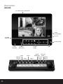
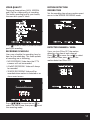
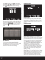
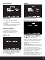
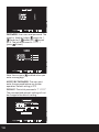
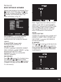
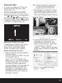
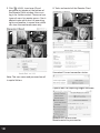
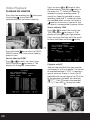
BDeye combined CCTV video door access system
U S E R M AN UAL
2
Contents
What is included and Optional Extras . . . . . . . . . . . . . . . . . . . . . . . . . . . . . . . . . . . . . . 3
Description . . . . . . . . . . . . . . . . . . . . . . . . . . . . . . . . . . . . . . . . . . . . . . . . . . . . . . . . . . . . . . 4
Installation . . . . . . . . . . . . . . . . . . . . . . . . . . . . . . . . . . . . . . . . . . . . . . . . . . . . . . . . . . . . . . 6
Operation . . . . . . . . . . . . . . . . . . . . . . . . . . . . . . . . . . . . . . . . . . . . . . . . . . . . . . . . . . . . . . . . 7
Operation Buttons . . . . . . . . . . . . . . . . . . . . . . . . . . . . . . . . . . . . . . . . . . . . . . . . . . . . . . . . 8
Setup . . . . . . . . . . . . . . . . . . . . . . . . . . . . . . . . . . . . . . . . . . . . . . . . . . . . . . . . . . . . . . . . . . . . 9
Network . . . . . . . . . . . . . . . . . . . . . . . . . . . . . . . . . . . . . . . . . . . . . . . . . . . . . . . . . . . . . . . . 15
Video Playback . . . . . . . . . . . . . . . . . . . . . . . . . . . . . . . . . . . . . . . . . . . . . . . . . . . . . . . . . 20
Operation Instruction . . . . . . . . . . . . . . . . . . . . . . . . . . . . . . . . . . . . . . . . . . . . . . . . . . . . 21
Technical Specification . . . . . . . . . . . . . . . . . . . . . . . . . . . . . . . . . . . . . . . . . . . . . . . . . . 22
What is included
Monitor
Camera
Remote Controller
Software
500GB Hard Drive
User Manual
Camera
Camera Extension Cable
15m Camera Cable
Optional Extras
VDE Call Point
VDE Extension Cable
3
Description
MONITOR
2.5" HARD DISK CARTRIDGE
VOICE
ADJUSTMENT
A/V OUT
POWER
SWITCH
IR RECEIVER
LOAD
SPEAKER
POWER
INDICATOR
CAM 4
SENSOR
DEVICE
4
TOUCH
PANEL
CAM 2
CAM 3
CAM 1
MIC
TCP/IP
NETWORK
VDE CALL
POINT 1
VDE CALL
POINT 2
POWER
SUPPLY
INSERTION OF THE HARD DISK DRIVE
1. Follow the direction marked beside
the button to open the cover of the
hard disk cartridge.
2. Insert the hard disk paying attention
to the direction of the slot.
3. Push the hard disk down.
4. Close the cover.
5
Installation
WIRING
POWER
SUPPLY
TCP/IP (Network)
6-Pin connector for camera (BDeye Cam)
1
2
3
6
5
4
1 – GND for Video (Black)
6 – Audio In (White)
2 – Control (Blue)
5 – Video In (Yellow)
3 – GND for Audio & Power (Brown) 4 – VDD (Red)
4-Pin connector for video door entry call point (BDeye VDE)
1
4
2
3
1 – GND (Black)
2 – Video (Yellow)
3 – B+ (Red)
4 – Audio (White)
5-Pin connector for alarm device
5
1
2
6
4
3
1 – Alarm Out (Blue)
2 – Alarm In (Brown)
5 – GND (Black)
4 – Sensor 1 (Red)
3 – Sensor 2 (White)
Operation
HOW TO TURN ON
1. Push the power switch on the left side of the indoor unit, the monitor will start.
2. The monitor shows quad monitoring at start up as shown in Fig. 1 after system check.
3. If the time is within schedule recording time, the system will automatically start the
schedule recording approximately 10 seconds after the boot up as shown in Fig. 2.
1
2
1
2
3
4
3
4
2 0 1 0 / 1 0 / 2 1
Fig. 1
2 2 : 2 0 : 5 1
A?REC *75% 2 0 1 0 / 1 0 / 2 1
2 2 :
Fig. 2
HOW TO TURN OFF
1. Press the stop button
to stop recording.
2. Push the power switch on the left side of the indoor unit, the monitor will turn off.
DESCRIPTION OF DISPLAY
1,2,3,4
Channel Number
Video recording status. Red dot means recording.
Channel with audio input. Red icon means recording and white one means no recording.
The recording status can be changed in the SETUP->AUDIO PORT->RECORDING.
Outputting audio information. One channel audio can be outputted by the microphone
of the monitor. The user can press to select one channel audio to be outputted or close
the audio outputting.
A?REC
S?REC
N?REC
*75%
Always recording.
Sensor recording.
No recording.
Used space of hard disk. "*" means that the disk is in overwriting status.
DATE/TIME System date/time.
Note: Your previous settings of the monitor will remain the same when it's restarted from
power cut or shut off.
7
Operation buttons
ICON
NAME
OPERATION
Display
Full Screen Display of Channel 2/Number 2
Display
Display
Display
Display
Setup
Audio Channel
REC
Stop
Play
Move/Confirm
Move/Confirm
Move/Confirm
Move/Confirm
Move/Confirm
Talk/Monitoring
Unlock
Display On/Off
Full Screen Display of Channel 1/Number 1
Full Screen Display of Channel 3/Number 3
Full Screen Display of Channel 4/Number 4
Quad Display
Enter/Exit Setup
Switch/Close Audio Output
Start/Stop Recording
Stop
Play/Pause
Up
Down
Left/Backward
Right/Forward
Choose/Confirm
Talk/Monitoring/Turn on Monitor Display
Unlock
Turn On/Off Monitor Display
Note: Buttons on the remote controller are same functions as on monitor buttons, except
the
(On/Off) on the remote controller.
8
Setup
To enter SETUP menu, press the stop
button
, then press
.
The following screen will display:
SETUP
CAMERA ON/OFF
RECORD ON/OFF
COVERT CHANNEL
[ OFF ]
AUDIO PORT
RECORDING FRAME RATE
VIDEO QUALITY
SETUP
RECORD SCHEDULE
CAMERA ON/OFF
MOTION DETECTION
RECORD ON/OFF
ALARM
COVERT CHANNEL
HARD DISK DRIVE
AUDIO PORT
GENERAL
RECORDING FRAME RATE
NETWORK
VIDEO QUALITY
DEFAULT
RECORD SCHEDULE
MOTION
DETECTION
M
OVE
CHOOSE
NORMAL
[ OFF ]
NORMAL
EXIT
ALARM
HARD DISK DRIVE
GENERAL
NETWORK
DEFAULT
CAMERA ON/OFF
MOVE
RECORD ON/OFF
CHOOSE
EXIT
Each channel can be set ON or OFF. If set
to1 OFF,
the corresponding
2 ONscreen goes
ON
CAMERA ON/OFF
black and recording
function is disabled.
Default is ON.
1
1
2 ON
ON
Video recording function of each channel
can be enabled or disabled separately. If it is
set to OFF, the screen will keep showing the
surveiled scene, but it will not be recorded.
3 OFF
3 OFF
2 ON
ON
RECORD ON/OFF
CAMERA ON/OFF
4 OFF
MOVE
CHOOSE
4 OFF
EXIT
MOVE
CHOOSE
EXIT
Press
to move the red
to
select the channel, then press to set the
camera connected to this channel to be
ON or OFF.
3 OFF
4 NO CAM
MOVE
CHOOSE
EXIT
Press
to move the red
to
select the channel, then press to set the
camera connected to this channel to be
ON or OFF.
NO CAM means there is no camera being
connected with the corresponding channel
of the monitor.
9
COVERT FUNCTION
CAMERA ON/OFF
You can choose one channel to be covert.
This covert channel will not be shown on
the screen, but it can be recorded.
Frame rate of each channel can be set
separately to 1,2,3,4,5,6,12,16,25 FPS.
Total frame rate of four channels is 50 FPS
for PAL TV system and 60FPS for NTSC TV
system. For example, if you set 16FPS for
channel 1, channel 2 and channel 3 for a
monitor in PAL TV system, you can choose
1FPS or 2FPS for channel 4 and keep the
selected recording frame rate of other
channels same, however, if you want to set
the frame rate of channel 4 to a option
more than 2FPS, the frame rate of other
channels will be reduced automatically.
1
RECORDING FRAME RATE
TOTAL 32 FPS
AUDIO PORT
Two channels of audio input are available.
Audio acquisition devices can be connected
to any two video channels. Users can enable
or disable recording of audio separately by
setting the RECORDING.
2 16 FPS
16 FPS
3 16 FPS
4 2 FPS
MOVE
CHOOSE
EXIT
Press
to move the red
to
the channel to be set, then press
to set
the recording frame rate of this channel to
a proper value.
Note: Microphone of the monitor is an audio
acquisition device for audio port 1.
10
VIDEO QUALITY
MOTION DETECTION
There are three options (HIGH, NORMAL
and LOW) for video quality of recording.
The better recording quality you choose,
the more disk space it takes.
RECORD TIME
Press button to select a preferred video
quality of recording.
RECORDING SCHEDULE
Users can schedule the recording hour by
hour for the whole day. The three options
of recording are as following,
> NO RECORDING: Video from the CCTV
cameras will not be recorded.
Set the recording time when a motion event
occurs in the SENSOR RECORDING mode.
DETECTED CHANNEL / AREA
Users can turn ON or OFF the motion
detection function of each channel.
Press or to move the red to select
the channel, then press to set the
motion detection ON or OFF.
> ALWAYS RECORDING: Video will always
be recorded.
> SENSOR RECORDING: Video will be
recorded when motion is detected or an
alarm event occurs.
Press
to move the red
select the time frame, then press
the recording mode.
to
to set
11
Press to move the red to the AREA,
then press or to select a channel and
press to trigger the motion setting.
ALARM SETUP
VIDEO LOSS
Four sensitivity levels can be selected and
the sensitivity increases with the number
rising. Press
to select the grid.
Then press to change the sensitivity
level.
IR TRIGGER
Only human motion can activate the
recording in the SENSOR RECORDING mode
if IR TRIGGER is set ON. Otherwise all
motion will activate the recording.
In the monitoring status,if the video cable
connection is not good, the indoor unit will
alarm with beep sound. Users can set it ON
or OFF.
ALARM DEVICE
Alarm sensor setting: You can connect 2
alarm sensors with the monitor and set them
to be bonded with 2 of the 4 CCTV channels.
If an external alarm sensor is connected and
it's triggered by an event, the monitor will
alarm with beep sound and also activate the
recording if it's in SENSOR RECORDING
schedule. If you have connected with an
external alarm output device, it will send an
alarm. Users can also enable or disable the
connected alarm sensors by setting them
OPEN or CLOSE.
Alarm Time: It's for setting the time of alarm
outputting when an alarm event occurs. OFF
means no response to the alarm event and
CONT means constantly response to the
alarm event till someone stop it manually.
12
HARD DISK DRIVE
GENERAL
HDD information
To set system-related issues.
> ST9408221AS: Hard disk model.
DATE/TIME: Set the system time.
> HDD CAPACITY: The capacity of current
hard disk.
> HDD USED: The occupation of hard disk
space, displayed in percentage.
OVERWRITE ENABLED
If it is set to YES, the system will
automatically overwrites the earlier
footage when the storage is full.
FORMAT HDD
Press or to move the red to the
digit which you are going to change, then
press to change the numbers.
RING: You can choose a preferred ring for
visitors calling. There are total 9 options.
LANGUAGE: Chinese and English are
available.
Format the current hard disk. Password set
in the GENERAL is required for formatting
the hard disk and the initial password is
111111 (press 6 times).
TFT-LCD DISPLAY: When it's set to ON, the
screen will be always lighted, and if it's set
to OFF, the screen will be turned off in
normal, but it will be activated when there
is a call. Users can press to open the
screen display when it's turned off.
TFT-LCD SETTING: Users can adjust
BRIGHTNESS, CONTRACT and SATURATION
of the screen display to a proper value.
13
PASSWORD: Users can reset password. The
length is fixed to 6 digits, stands for 1,
stands for 2, stands for 3, stands
for 4. The initial password is 111111
(press 6 times).
Note: You can press
enter a wrong digit.
to delete when you
ACCESS BY PASSWORD: The user must
enter the password before any further
operation. Default setting is OFF.
DEFAULT: The initial password is "111111".
The password and network setting will not
be changed after default setting.
14
Network
BASIC SETTING OF NETWORK
Connect the monitor to the network. Press
to enter the SETUP menu. Use and
button to select NETWORK, then press
to enter the NETWORK menu. The
screen will display as Fig. 33.
NETWORK
MAC ADDRESS...
IP ALLOCATION..
IP ADDRESS.......
<00:BB:4B:E8:21:A8>
[DHCP]
<0.0.0.0>
SUBNET MASK...
<0.0.0.0>
GATEWAY...........
<0.0.0.0>
DNS SERVER 1..
<0.0.0.0>
DNS SERVER 2..
[0.0.0.0]
HTTP PORT........
[
Note: To guarantee the stability of the IP
address in the LAN. It's recommended to
obtain the IP automatically by DHCP mode
and write down your current IP address,
then change IP allocation to static and
enter IP information in the network
setting.
80] 80,1024-49151
USER SETUP.....
DDNS SETUP.....
MOVE
CHOOSE
EXIT
STATIC IP SETTING
MAC ADDRESS: It is a unique identifier
assigned to network interfaces for
communications on the physical network
segment.
If STATIC IP is selected, users should set IP
ADDRESS, SUBNET MASK, GATEWAY and
DNS SERVER 1 manually. DNS SERVER 2
can be set optionally.
IP ALLOCATION: Supports both
DHCP(dynamic) and STATIC IP.
IP ADDRESS
DHCPIP SETTING
If DHCP is selected, IP ADDRESS, SUBNET
MASK, GATEWAY and DNS SERVER 1 will be
obtained from the DHCP server
automatically. Users can set the DNS
SERVER 2 optionally.
Press or to move to the digit to be
set, then press or to move to the
corresponding digit and press to choose
it. Repeat this step untill the IP ADDRESS
is set correctly.
DNS SERVER 2
Press or to move to the digit to be
set, then press or to move to the
corresponding digit and press to choose
it. Repeat this step untill the DNS SERVER
2 is set correctly.
15
SUBNET MASK
DNS SERVER 1
Press or to move to the digit to be
set, then press or to move to the
corresponding digit and press to choose
it. Repeat this step untill the SUBNET
MASK is set correctly.
Press or to move to the digit to be
set, then press or to move to the
corresponding digit and press to choose
it. Repeat this step untill the DNS SERVER
1 is set correctly.
GATEWAY
DNS SERVER 2
Press or to move to the digit to be
set, then press or to move to the
corresponding digit and press to choose
it. Repeat this step untill the GATEWAY is
set correctly.
Press or to move to the digit to be
set, then press or to move to the
corresponding digit and press to choose
it. Repeat this step untill the DNS SERVER
2 is set correctly.
Note: Please restart your monitor after
network setup.
16
OPEN HTTP PORT
It's necessary to open the HTTP port of
the monitor before the users can get
remote access to it.
Assign a port number to be opened
Optional HTTP PORT is 80,1024 to 49151.
Press or to move to the digit to be
set, then press or to move to the
corresponding digit and press to choose
it. Repeat this step untill the HTTP PORT is
set correctly. The default port is 80.
Note: The port number can be omitted if
you use the default port 80, for
example http://192.168.18.101.
2. After the plug-in installation, it will popup a "Remote Client" window as shown
below. If not, please close and restart IE
then input the network address correctly.
1
2
3
4
A?REC *75% 2 0 1 0 / 1 0 / 2 1
Open the HTTP PORT on a router
It might be done in different way to open
an HTTP PORT on different types of
routers. For a specific router, please
contact the vendor to get the detail.
Remote monitoring and control
1. Open an IE browser, enter the monitor's
IP address such as
http://192.168.18.101:6666 in the LAN
or your WAN IP such as
http://113.110.152.49:6666 in the
address bar. First visit will be prompted
to install plugin, select "Yes" to install it.
Installation will begin automatically
after downloading. If the plugin does not
download automatically, please click
"Download" in "If the plugin can not
download, click here". Double click the
downloaded file to install it when the
download is finished.
2 2 :
3. If the remote client does not show the
monitored scene, please lower the
security level of your browser. Open
Internet Explorer browser, select "Tools"
- "Internet Options" - "Security" "Internet" - "Custom Level". In the popup
window, open all theActiveX plugins and
controls.
4. Click
to enlarge the preview
screen two times.
17
5. Click
, input user ID and
password will appear at the bottom of
the Remote Client window. Users can
log in for further control. There are two
types of users for remote access. One is
administrator which has full operating
rights and another is normal user which
can view the monitored scene only.
1
6. Tools and control of the Remote Client
1
2
3
4
2
A?REC *75% 2 0 1 0 / 1 0 / 2 1
3
2 2 :
4
A?REC *75% 2 0 1 0 / 1 0 / 2 1
2 2 :
Connected: Current connection status.
Note: The user name and password are all
in capital letters.
Capture Tools: For capturing images and video.
Remote DVR Control Panel:
Remote control to your monitor.
18
DDNS setup
To setup Dynamic Domain Name Service.
The user is required to register and create
a host name from the DDNS service
provider WWW.DYNDNS.COM. Then enter
user ID(user name), password and domain
name obtained in the DDNS SETUP of the
monitor.
4. Enter http: //remoteview. dyndns free. com: 6666 in your browser to get
remote access to your monitor.
1
2
3
4
A?REC *75% 2 0 1 0 / 1 0 / 2 1
2 2 :
1. Visit website http:// www.dyndns.com.
2. Sign up an account and create a host
name such as ‘remoteview. dyndns free. Com’.
3. DDNS Setup in the monitor
Enter the host name, Username and
Password you obtained from the DDNS
service provider in the DOMAIN NAME,
USER ID and PASSWORD of the DDNS
SETUP menu as shown below.
19
Video Playback
PLAYBACK ON MONITOR
Press the stop recording key , then press
the play key , the system will
automatically play the latest video clip.
1
2
Users can press or to select from
different events, and press to play. In
the event list, "T" stands for video clip
recorded in always recording mode. "S"
stands for video clip recorded in sensor
recording mode and "C" stands for video
clip recorded when a visitor call. When a
appears on an event, it presents that
this event is accompanied by power failure.
Search video by TIME
3
Press or to select the search type
TIME, then press to choose it. The
display will change as per Figure below.
Users can input the time which he wants
to check the video and press to play.
4
2 0 1 0 / 1 0 / 2 1
2 2 : 2 0 : 5 1
Press the menu key to enter the VIDEO
SEARCH menu. Users can search video by
event or time.
Search video by EVENT
Press or to select the search type
EVENT, then press to choose it. The
display will change as shown below.
Playback with PC
Take out the hard disk from your monitor
and connect it with a computer. The format
of recorded footage is ".MCG". It requires a
special software to play it. Insert the CD
provided with the package to the CD driver
of the computer and open the software
. Click to open the recorded
footage. Then click to play the video.
1
2
3
4
2010/10/21
20
22:20:51
Operation instruction
MCG file dump
Always Top Window
50% Screen
100% Screen
150% Screen
Close
Open another MCG file
Jump back 60 Sec
Jump back 10 Sec
Switching storage device
Preferences - Change the application's default setting
Move the
window
Audio Output Setting / Volume control
Drag the window by its part below title bar to move it
Reverse Playback
Pause
Forward Playback
Jump forward 10 Sec
Jump forward 60 Sec
Play frame by frame backward
Play frame by frame forward
Record
Capture [BMP]
21
Technical Specification
SYSTEM
Control system
LINUX
System resources
Triplex , supports simultaneous recording, video playback and network operations
Operation interface
User-friendly menu interface
User interface
Panel touch button and remote control
Video protocol
MPEG4
Audio protocol
ADPCM2
VIDEO
Video input
4 x camera plus 2 x video door entry
Video output
One way
Preview resolution
720×576@25fps (each channel)
Video recording
720×288@50fps (total resources)
Image division
Single or quad screen display
Recording
Scheduled or motion detection recording
On screen display
Channel and time information
AUDIO
Audio input
Two-way
Audio output
One way
VDE audio
Full duplex audio
HARD DISK
Hard disk
500Gb built-in one SATA interface, 2.5 inch hard MAX 500Gb
VIDEO RECORDING AND PLAYBACK
Video recording mode
Video recording by manual, schedule, motion detection, sensor and visitor call
Multi-channel playback
Four channel quad or single channel
VIDEO DOOR PHONE FUNCTIONS
Calling
Two channel
Video recording
Visitor calling and video recording
Unlocking
Electric lock release function
INTERFACE
22
Networking interface
One RJ45 10M/100M network interface
Camera interface
Four 6-core mini din video (Max 80M)
VDE interface
Two 4-core mini din video (Max 80M)
Alarm interface
One 5-core
AV output interface
One AV 3.5
POWER SUPPLY
Video call point
Four way camera powered by integral central power supply
Outdoor station
Two way outdoor station powered by integral central power supply
SPECIFICATIONS
Power supply
DC +12V 4.5A
Screen
8” TFT-LCD
Resolution
800x600
Temperature Range
-10ºc – +70ºc
Dimensions
250 × 210 × 35mm
Installation methods
Desktop or wall mounting options
CAMERA
Sensor
1/3" LG CCD
Effective Pixel
500(H)×582(V)
Resolution Ratio
720x576
Frame
PAL: 1-25 fps
Electronic shutter speed
1/60 – 1/100,000 S(NTSC)
Horizontal resolution
420TVL
Lens
3.6MM
IR viewing distance
10m
Power supply
DC 12V
Operation Current
220mA
Operation Temperature
Indoor/outdoor, -10ºc – 60ºc
Weatherproofing
IP55 rated
23
Technical Support 01527 515145
Elite Security Products
Unit 7, Target Park, Shawbank Rd
Lakeside, Redditch B98 8YN
Telephone: 01527 515150
Technical Support: 01527 515145
email: [email protected]