1
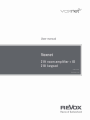
Introduction
network receiver
Klk
4
OM V1.01
SW 80-1.0.2
D 1.0
1
Contents
Voxnet 219
Welcome ..............................................2
Voxnet 219 room amplifier .................3
Commissioning ............................................ 3
Scope of delivery......................................... 3
Safety ........................................................... 3
Fuse.............................................................. 3
General safety instructions......................... 4
Safety measures ......................................... 5
Regulations pertaining to the unit .............. 6
Rack installation ..................................... 7
Environmental conditions in the rack .. 8
Installation
with
wall-mounting
bracket .................................................... 9
Voxnet 218 keypad ............................ 23
DIP switch ............................................ 24
RC5 codes Voxnet 218 ......................... 25
[Address] [Command] ......................... 25
Cabling .................................................. 26
CAT cable cabling plans ..................... 26
Parallel switching ................................ 26
Technical data ..................................... 27
Network terminology glossary .. 28
DHCP ..................................................... 28
DNS ....................................................... 28
Ethernet network ................................. 28
Gateway ................................................ 28
Front of the Voxnet 219 ............................. 10
IP address ............................................. 28
Status LED ............................................. 10
LAN ........................................................ 29
Display ....................................................... 11
MAC Address ....................................... 29
Connection panel ...................................... 13
NAS ....................................................... 29
Detailed description /Connection panel ...... 14
Power line – LAN ................................. 29
IR Link .................................................... 14
Proxy server ......................................... 29
Network ................................................. 14
Router (WLAN Router) ........................ 29
Trigger IN .............................................. 14
Server .................................................... 29
Trigger OUT........................................... 14
UPnP-AV ............................................... 30
.............................................. 14
VLAN...................................................... 30
Voxnet peripherals............................15
Appendix ............................................ 31
Multiroom example: Voxnet with 2 rooms
................................................................ 16
Warranty .................................................... 31
Voxnet Configurator .................................. 17
Environmental protection .......................... 31
USB
Technical data ...................................... 19
I/O module ..........................................20
Installing modules ..................................... 20
Connections............................................... 21
Connection description ....................... 21
Technical data ...................................... 22
1
Copyright .................................................... 31
Voxnet 219
Safety
WELCOME
as soon as an audio signal is detected on
the corresponding input.
Voxnet is an Ethernet-based multiuser /
multiroom audio system developed by
Revox with a new, unique operating
philosophy and an impressive audio
quality. This is characterised by
streaming at CD level quality and with
the smallest latency periods, so that
music can be heard in its purest form,
with practically no delay, in each room.
One of the Voxnet system's powerful
tools is the range of trigger options
available, that make it possible to control
the system in many ways externally,
using, for example, the five input
triggers: Infrared (RC5), Audio, Room,
Source and Voltage (IN). In the opposite
direction, other devices can be
controlled and/or addressed through the
output trigger (OUT / 12 VDC).
The hardware audiophile core of the
system is represented by the modular
Voxnet 219 stereo amplifier. Its powerful
2 x 50 watt outputs can even provide
enough power to drive column speakers.
The integrated DSP (Digital Signal
Processor) allows adjustments to be
made to handle all Revox speakers. You
just have to select the corresponding
Revox speaker in the Configurator list
and then define the positioning and/or
the installation method. This is all you
need to achieve the optimum in sound
quality for a clean reproduction. In
addition, a professional 8 band equaliser
(parameters: Q, Fc, Gain) allows you to
balance the system to meet your
personal preferences.
As well as the triggers, the Voxnet
system also offers proxy servers that can
be used to control devices outside the
Voxnet world, using IP commands.
Revox can supply corresponding 1 U
height shelves to accommodate 2 Voxnet
219s, for quick and secure installation in
a 19" rack (Article no.: 1.563.090.00). A
single bracket (Article no.: 1.563.091.00)
is also available for wall-mounting.
This product innovation from Revox
stands out as a true system for life,
thanks to its legendary robustness and
longevity, which the brand is known for
throughout the world.
Traditional
music
sources,
both
analogue and digital, can be connected
through the optional I/O module.
Needless to say, this is possible in HD
quality with data rates of up to 192
kHz/24 bit. In order to deliver even more
comfort, all inputs are equipped with
freely definable detector switching to
permit automatic switch-on, for example,
2
Safety
Voxnet 219
VOXNET 219 ROOM AMPLIFIER
Scope of delivery
Commissioning
Voxnet 219 Room Amplifier (1x)
Please check the unit and accessories
after unpacking, to ensure that
everything is there and that there are no
signs of transit damage. Read the User
manual through carefully before starting
to use the unit. Keep the manual for later
reference. A unit that shows signs of
mechanical damage or which has had
liquid in it may not be connected to the
mains supply.
Power cable (1x)
Network cable (1x)
4 self-adhesive rubber feet
Safety
Take note of the label on the back of the
unit.
Only use the mains cable supplied. If a
different cable has to be used, it must
comply with the values 10A/125V. Any
alternative power cable used must have
corresponding
certification
(UL/CSA/VDE).
The unit’s power supply and connections
values (mains voltage, frequency) must
be checked before connecting it to the
mains.
In order to avoid the risk of an electric
shock, do not open the housing.
Maintenance and repairs should only be
carried out by qualified experts.
Use of switch-on current limiter
In the case of the installation of more
than 4 Voxnet 219s per secured 16A
circuit, Revox recommends the use of a
switch-on current limiter.
This provides effective protection
against a mains circuit breaker being
tripped during switch-on following a
power outage or an overnight shutdown.
3
Fuse
The Voxnet 219 does not have any fuses
that can be replaced by the user. The
special fuse in the power supply unit
may not be exchanged by the user.
In this case of a fault, please contact
your nearest Revox Service Point.
Voxnet 219
Safety
General safety instructions
There must be easy access to the
power plug so that the unit can be
unplugged at all times.
Please follow the instructions in the
User manual supplied.
Do not position the unit close to strong
heat sources or in direct sunlight.
Lay the power cable such that it
cannot be damaged. The power cable
should not have kinks or by laid over
sharp edges. It should not be walked
on or be exposed to any chemicals.
The last point is valid for the whole
unit. A power cable with damaged
insulation can lead to electric shocks
and represents a fire hazard.
Please take note of the following, if the
Multiroom amplifier is to be installed in
a cabinet or closed shelves: Allow at
least 5 cm of free space around the
device, so that the air can circulate
freely and so that there is no build up
of heat. Do not cover openings on the
back or front walls of the unit.
Never pull on the cable when plugging
the unit in or out. Always hold the plug.
It must be ensured that the correction
functioning of the unit's ventilation
openings is not affected by being
covered, e.g. by curtains, newspapers,
table cloths, or similar.
Liquids, flammable or other objects
should not be inserted in the unit’s
openings as this can lead to faults, fire
or an electrical shock.
This unit conforms to protection class
2. This means that with this unit, the
ground cable is not connected to the
housing, in order to effectively
eliminate sound-damaging groundloops. With these Multiroom amplifiers
however, Revox uses the ground cable
for the reduction of noise fields. For
this reason, both the supplied cable
and the connection panel are fitted
with a ground cable.
Do not expose the device to splash
water or high levels of humidity. Do
not stand containers filled with liquid,
e.g. flower vases, on the device.
It is only designed for operation in
temperate, non-tropical climates.
Take note of and follow the safety advice
on the following pages.
Unplug the unit if you are going to be
absent for a longer period of time.
Unplug the unit from the mains during
storms. Voltage peaks through the
mains power supply caused by
lightning strikes can damage the unit.
4
Safety
Voxnet 219
Safety measures
- Dust
Read and take note of the following
safety advice for your own safety and to
avoid unnecessary damage to your
equipment. Please keep this safety
advice in a safe place for future
reference.
- Interventions in the inside of the device
Avoid locating the unit in a position
which:
- is exposed to direct sunlight
- Do not stand any articles with open
flames, e.g. lit candles on the unit.
Please note
In order to exclude the risk of an electric
shock, do not remove the housing. Only
have any repair work carried out by a
Revox specialist dealer.
- is directly next to a source of heat
Volume
- has poor ventilation
Loud music can cause hearing damage.
Avoid extremes of volume, particularly
over longer periods of time.
- has a dusty atmosphere
- is unstable
- has high humidity
The guarantee covers intended usage of
the device.
High build-ups of dust and humidity
cause creepage current in the device
that can cause a risk of shocks when
touching the unit or lead to a fire.
If you have moved the unit from a cold to
a warm environment, leave it switched
off for about two hours because of a
possible build up of condensation
dampness.
You should always switch your Voxnet
219
off
before
connecting
or
disconnecting
other
devices
or
speakers.
Protect your unit from:
- Damp, dripping or splash water and steam
- Knocks and mechanical loads.
- Magnetic and electrical fields
- Cold, heat, direct rays of the sun and
severe changes of temperature
5
Supervision
Do not allow children to handle the
equipment without supervision. Do not
allow children in close proximity to the
unit. Do not operate the Multiroom
amplifier without supervision. Unplug the
unit if you are going to be absent for a
longer period of time.
Cleaning
The unit should be cleaned using just a
damp, soft and clean cloth without any
abrasive cleaning agents.
Voxnet 219
Safety
Regulations pertaining to the unit
In EU and EEC countries, Revox offers a
guarantee on units bought in the EU,
over and above the statutory rights of
guarantee claims against the seller. The
guarantee covers material and labour
during the period of the guarantee,
which is defined by the Revox Sales
Partners in the individual countries that
make up the EU.
In all countries, the guarantee services
offered by the Revox Sales Agent are
over and above the statutory regulations.
They are only valid in the country of
purchase. Proof of purchase from an
authorised Revox Partner must be
produced to make a claim on the
guarantee.
The guarantee is made null and void in
the case of incorrect intervention
measures
or
non-professionally
executed repairs.
6
Operation
Voxnet 219
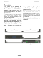
Rack installation
The Voxnet 219 is designed for
installation in a 19" rack. A shelf / tray
(Revox Article no.: 1.563.090.00) is
available as an accessory, which can
take two Voxnet amplifiers. The height of
the shelf is 1 U.
The tray can be built into the rack with
and without Voxnet amplifiers. Both
options are possible depending on the
installation environment.
The Voxnet 219 has a recess to the left
and right of the front edge which the
metal lugs of the tray (upper picture / )
fit into. Locate the amplifier, lined up
with the right or the left of the tray and
push it backwards until it reaches the
7
back wall of the tray. The amplifier is
now fixed in place horizontally at the
front and vertically.
Now turn your attention to the rear of the
tray. Two knurled thumb screws are
provided with each amplifier for fixing it
into place (lower picture / ). Screw the
amplifier into place with these until they
are hand-tight.
This completes the installation of the
Voxnet 219.
Voxnet 219
Operation
Environmental conditions in the rack
Use of switch-on current limiter
In the case of a rack installation, you
must ensure that the inside temperature
of the rack does not exceed +40°C /
+104°F. If necessary, the rack must be
actively cooled using a fan.
In the case of the installation of more
than 4 Voxnet 219s per secured 16A
circuit, Revox recommends the use of a
switch-on current limiter.
This provides effective protection
against a mains circuit breaker being
tripped during switch-on following a
power outage or an overnight shutdown.
The Voxnet amplifier itself is fitted with
an active fan control and controls its
own inner temperature. Cool air is
sucked in at the front of the amplifier,
drawn through the unit and blown out of
the slots at the back. For this reason,
cool air must be able to get to the front
of the amplifier to be drawn in, even if
the rack door is closed. Multiple trays
can be mounted underneath each other
in the rack, without having to leave any
gaps between them.
Stack of 8 Voxnet 219s
8
Operation
Voxnet 219
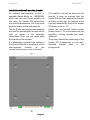
Installation with wall-mounting bracket
An optional wall-mounting bracket is
available (Revox Article no.: 1.563.091.00),
which can take one Voxnet amplifier. In
this case, the Voxnet 219 connections
are directed downwards. The front panel
with the display is directed upwards.
The amplifier can now be placed on the
bracket. It must be ensured that the
Voxnet 219 lies flush against the bracket
and that its two lugs are located in the
recesses beneath the front of the Voxnet
219 (lower picture / ).
The 4 x 30 mm pan head screws supplied
are used for mounting the bracket on the
wall, as shown in the assembly
instructions. Then, you can simply hang
the bracket on the screws.
Finally, the two knurled thumb screws
(lower picture / ) are screwed into the
amplifier's locking threads and handtightened.
It is advisable to complete the cabling of
the Voxnet 219 before mounting it on the
wall-mounted
bracket
as
the
connections are very close to the wall.
9
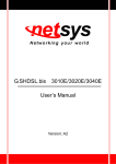
The picture shows the positioning of the
Voxnet 219 (transparent) on the wallmounted bracket (dark in the
background).
Voxnet 219
Operation
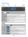
Front of the Voxnet 219
Name
Function
Info display
Displays various operating data details. Called through the Setup button
Ventilation intake
Do not cover the opening - required for fresh air intake
Monitor [socket]
Headphone output - 3.5 mm, stereo jack
Power [LED]
Operational state status display
Setup [button]
For calling up various operational data in the info display [activate
bootloader]
Voxnet [LED]
Voxnet system activity display
Status LED
Power
Voxnet
Display
Function
Standby
Bootloader activate: [Press and hold the Setup button and
power up the Voxnet 219]
Voxnet 219 is switched on: IP not assigned or has been
subsequently separated from the network
Voxnet 219 active in the background: one or more inputs from
an optional module are in sensitive mode and/or are being
streamed from other amplifiers.
Voxnet 219 is switched on: IP is assigned
10
Operation
Voxnet 219
Display
Various operational data can be called
up through the Setup button.
The Voxnet 219 is supplied with the current Voxnet server
firmware over the bootloader.
The Voxnet 219 starts up after the firmware has been 100%
updated. This state is shown briefly in the display.
After start-up, the Voxnet 219 receives its IP address from the
router via DHCP. This can take a few seconds.
When the unit is delivered, theRoom is displayed with the
corresponding MAC address from the Voxnet 219. The room
identifier is completed with a (0). After configuration through
the Voxnet Configurator, the display shows the assigned
"Room alias". A level display gives information about the
amplifier / output volume status.
As with the room, the Source is defined as a combination
with the MAC address. The source identifier is competed
with a (0). After configuration through the Voxnet
Configurator, the display shows the assigned "Source alias".
A level display gives information about the input level of the
current source.
Source index: CO: coaxial OP: optical AN: analogue
The Trigger ([IN/OUT) is also defined as a combination with
the MAC address. The trigger is completed with an indexing
value. After configuration through the Voxnet Configurator,
the display shows the assigned "Trigger Alias". The status of
the IN and/or OUT trigger is shown in the bottom line of the
display.
11
Voxnet 219
Operation
You can read off through the infrared display which RC5 code
(address / command) was received last. A current RC5
reception is indicated by the display of [IR], shown in a light
colour here.
The version number shows the current firmware version of
the Voxnet 219.
If a module is installed in the Voxnet 219, its identity can be
determined through the display article number, here for
example, 1.563.080.00 from the I/O module.
The Voxnet 219's IP address that it received from the router
via DHCP is shown here.
Display of the Voxnet 219's own MAC address.
The Voxnet 219 switches itself off after the display loop is
completed assuming that no audio input has detected a
signal. Otherwise, the next time the Setup button is pressed,
the room identifier is displayed.
12
Operation
Voxnet 219
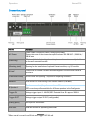
Connection panel
Name
Function
AC Power
Power cable connection (class 1 with ground cable)
Please take note of the connection specifications: 100-240 VAC~ / 50-60 Hz /
140 W max.
[Retaining]
M4 threaded hole for locking the unit in place on the rack-assembly shelf or
on the wall-mounted bracket.
[Blanking plate]
Opening for the installation of optional Voxnet modules, e.g. I/O module
IR Link*
Connection for Voxnet 218 wall-mounted keypad or various other Revox IR
receivers.
[Ventilation outlet]
Do not cover the opening - required for expelling heated air
Network
RJ45 socket for LAN cabling in the Voxnet network (100 Mbit)
R Speaker L
Speaker connection / Impedance: at least 4 Ω
DSP correction profiles available for all Revox speakers in the Configurator
Trigger IN
Voltage trigger input: 5 - 48 VAC/VDC. Potential-free. Ri: approx. 1000 Ω
Trigger OUT*
Voltage trigger output 12 VDC (configurable)
[Rating plate]
Unit-specific information
USB mini
USB mini socket for uploading bootloader
13 OUT: 80 mA
* Max. overall current from IR Link and Trigger
Voxnet 219
Operation
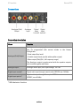
Detailed description /Connection panel
IR Link
Network
Various Revox products can be
connected to the IR Link:
• Voxnet 218 wall-mounted keypad (I =
23mA)
• M204 IR Receiver (I = 7mA)
• M204 IR Receiver flange (I = 7mA)
• M204 IR Receiver aluminium housing (I =
7mA)
Network connection to the Voxnet
network. This has to be separated from
other domestic networks physically or
through a VLAN. Minimum requirement:
100 Mbit; preferably a 1 Gbit network.
Trigger IN
Voltage-controlled input trigger (room
trigger) that is given its function through
the Voxnet Configurator. It can be used
both for the ON and the OFF state of
different actions.
All products have one thing in common,
that they send and/or forward RC5
commands to the Voxnet 219. The Voxnet
218 is described in more detail in a
separate chapter in this manual.
Input voltage can be between 5 and 48
volts, DC or AC. The IN trigger applies a
load of approx 1000 Ω to the supplying
source.
If the Voxnet 219's Trigger OUT is not
being used, devices with an overall
current of up to 80 mA may be
connected to the IR Link. The individual
current requirements in [mA] are listed
above.
Trigger OUT
Please note that cables with small crosssections or long cable lengths can
impact
both
qualitatively
and
quantitatively on the data signal to such
an extent, that it is no longer recognised
by the Voxnet 219.
The output trigger supplies 12 VDC. Its
function can be defined through the
Configurator or by using Voxnet text. The
OUT trigger can deliver an overall
current* of up to 80 mA, assuming that
the IR Link is not being used.
Max, lengths: 100 m at ≥ 0.25mm² / cable
strand (≤ AWG 23)
USB
USB mini connection for uploading the
Voxnet 219 bootloader as a fall-back
solution if the firmware should no longer
work correctly.
* Overall current
[IR-Link + Trigger Out): max. 80 mA
14
Operation
Voxnet 219
VOXNET PERIPHERALS
The Voxnet 219 is a network-based
amplifier that is assigned its functionality
and its operating mode configuration
through the Revox Voxnet Configurator.
This is described in a separate operating
manual, "Voxnet Configurator".
The following hardware peripherals are
needed for the Voxnet system:
•
DHCP router for the assignment of
IP addresses and for access to the
Internet for iRadio streams.
•
Synology NAS, as specified by
Revox. Contains a Voxnet server
software in the DSM package
centre. This includes all Voxnet
services, the rights management
and the licence server. The
Synology NAS can be ordered from
Revox in a pre-configured state,
including the Voxnet server
software.
•
Managed layer 2 switch (or higher)
with IGMP snooper functionality.
Revox has a list of recommended
switches to select from.
•
Fixed-cabling 1 Gbit LAN - 100 Mbit
to the clients (Voxnet 219) is
sufficient.
•
Separation of the Revox Voxnet
system in a VLAN or in a physically
separated network. In order to
ensure correct functioning, no
other clients, e.g. Smart TVs,
15
tablets, streaming products, etc.
should be present in the same
network. IP-controlled products
such as IP-serial converters or IPIP converters as offered by the
Global Caché company for
example, can of course be
operated in the Voxnet network.
Voxnet 219
Operation
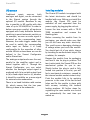
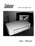
Multiroom example: Voxnet with 2 rooms
Components in the Voxnet system
1. DHCP router
2. Layer 2 switch (managed)
3. Synology NAS with Voxnet software
4. Voxnet 219 amplifier with I/O
5. Voxnet 218 wall-mounted keypad
6. Revox M2014 IR receiver
7. Revox speakers
16
Operation
Voxnet 219
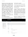
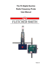
Voxnet Configurator
Revox offers a web-based GUI for the
configuration of the Voxnet system,
which can be called up through all
commonly used browsers such as
Firefox, Internet Explorer, Chrome etc.
This approach has the advantage that
the installer or system integrator has the
flexibility of choice and can use
platforms such as a Win-PC, Mac, iPad,
Android tablet or even in an emergency,
a Smartphone.
The Configurator communicates with the
Voxnet server that is located on the
Synology NAS. All configuration data
from the entire Voxnet system is stored
there.
Voxnet Configurator "General info"
17
Areas that affect the individual Voxnet
219 amplifiers are also stored locally
there.
All setup options are described in detail
in the separate "Voxnet Configurator"
and "Voxnet Text Protocol" operating
manuals. Here there follows just a small
glimpse into the options, in order to give
an overview of the new operation and
configuration philosophy of the Voxnet
system.
All the relevant settings for the Voxnet
system and its components are made in
the Configurator.
Voxnet 219
Operation
User dependent command:
Alongside the simple selection menus
such as those for the definition of the
analogue output of a Voxnet 219, more
extensive settings are carried out in the
"Voxnet Text" programming language.
This greatly increases the level of
freedom of how the amplifier can
operate. You can decide, for example,
what should happen when a signal is
detected at the Coaxial digital input. In
such a case, a traditional solution is that
the amplifier simply switches on
automatically and plays the signal
received over the Coaxial input.
@room:user:select:@local;stream:optical
In the examples above the local (i/o)
source optical will be assigned to the
actual room/ user.
In the same way, it would also be
possible to switch on a television
through an external IP-RS232 converter
when a signal is identified, by using the
Voxnet IP Proxy. In such a case, the
following Voxnet text command would
have to be entered for the corresponding
audio trigger:
This would be achieved with the
following Voxnet text command in the
audio trigger:
$p.sonytv:power_on (Voxnet IP-Proxy)
These two examples are just two
examples of the diversity of functions
offered by the Voxnet system.
Room dependent command:
@room:room:select:@local;stream:coaxial
18
Operation
Voxnet 219
Technical data
Output
Measured value
Measuring conditions
Max. output performance
2 x 50 W
1 kHz, 4 ohms [RMS]
Frequency range
20 Hz – 20 kHz
-3 dB
SNR
> 80 dB / typ. 85 dB
1 kHz, -8 dBFS coaxial
Channel separation
> 68 dB / typ. -80 dB
5 kHz, -8 dBFS coaxial
THD
< 0.04 % / typ. 0.025%
1 kHz, -8 dBFS coaxial
Frequency range
20 Hz – 20 kHz
-1dB
SNR
> 78dB
1 kHz at 650 mV Aux-IN
Channel separation
> - 62 dB
10 kHz at 650 mV Aux-IN
THD
< 0.015 % / typ. 0.008%
1 kHz at 650 mV Aux-IN
Headphones
Triggers
Input voltage Trigger IN
5 - 48 VAC or VDC
Trigger input impedance IN
Approx. 1000 Ω
Output voltage Trigger OUT
12 VDC
Max, output voltage OUT
80 mA
Configurable through Voxnet text
1
Device
H x W x D2
Dimensions
44 x 218 x 255
Weight
1.9 kg
Without packaging
Temperature range
+10°...40°C
DIN 40040
2.5 W
OFF
5.5 W
Sleep mode4
Approx. 9 W
Normal mode
140 W
Theoretical max. performance
Power consumption3
1
Overall current [Trigger Out] + [IR-Link] = max. 80 mA
2
A further 50 - 60 mm have to be calculated in for cable and plugs
3
Measured without any speakers or external devices, e.g. Voxnet 218 connected
4
Voxnet 219 is switched off; input detector from the module inputs is active however
19
Voxnet 219
I/O module
I/O MODULE
Installing modules
Traditional
music
sources,
both
analogue and digital, can be connected
to the Voxnet system through the
optional I/O module. Needless to say,
this is possible in HD quality with data
rates of up to 192 kHz/24 bit. In order to
deliver even more comfort, all inputs are
equipped with freely definable detector
switching to permit automatic switch-on,
for example, as soon an audio signal is
detected on the corresponding input.
However, the audio trigger cannot only
be used to switch the corresponding
audio input on. Rather it is freely
configurable for the execution of other
actions. Which actions these are can be
defined in the Voxnet Configurator
and/or Voxnet text.
The Voxnet I/O module is equipped with
the latest electronics and should be
handled with care. Before you install the
module, the Voxnet 219 must be
switched off and separated from the
power supply, by plugging the unit out.
The analogue output works as a Line out,
parallel to the amplifier output and is
muted together with it. Through the
Voxnet Configurator, you can select
whether the analogue output signal is
produced with (a) a variable output level
or (b) a fixed output level or (c), whether
it should be available as a mono-signal
for external active subwoofers.
There is no band limitation with version
(c), which means that the low pass
filtering is done in the subwoofer.
Loosen the two screws with a TX-10
TORX screwdriver and remove the
blanking plate.
Before removing the module from its
packaging, you should make sure that
you do not have any static electricity.
This could cause a damaging discharge
of voltage when you touch the module.
You should get rid of any static charge
by touching an earthed metal object like
a radiator, for example.
Remove the module from its packaging
and feed it into its plug-in position. The
two tracks inside the Voxnet 219 are the
mechanical guides for you to use.
Shortly before the plug-in card is fully
locked into position in its slot, you will
feel a mechanical resistance, caused by
the internal module socket contact strip.
Push the module fully in by applying
pressure in the area of the two screw
holes and fix the module in place with
both screws, including the toothed
locking washers. All further steps for
registering the new module are carried
out automatically the next time you
switch on.
20
I/O module
Voxnet 219
Connections
Connection description
Name
Function
Analogue audio output, e.g. for external output
Can be programmed with various modes in the Voxnet
Configurator:
Analogue [Sub] Output
- Fixed output (line level)
- Variable output (level parallel with amplifier output)
- Mono output [Sub] (R+L, full frequency range)
The Analogue output is synchronised with the speaker outputs
and is muted together with them.
Analogue input*
Analogue audio input, max. input voltage: 2.0 V eff.
Digital input coaxial*
Digital audio input through coaxial cable (SPDIFF max. 192 kHz)
Digital input optical*
Digital audio input through fibre optic - TOSLink
(SPDIFF, max. 96 kHz)
* With detector function
21
Voxnet 219
I/O module
Technical data
Inputs
Optical input
1
Data format
16, 20, 24 bit PCM - SPDIFF up to 96 kHz
Frequency response
20 Hz – 20 kHz
-1 dB
THD
< 0.02% / typically 0.01%
1 kHz / -12 dBFS
SNR
> 75 dB / typically 78 dB
1 kHz / -12 dBFS
Channel separation
> -90 dB / typically -97 dB
10 kHz / -12 dBFS
Coaxial input
Data format
16, 20, 24 bit PCM - SPDIFF up to 192 kHz 2
Frequency response
20 Hz – 20 kHz
-1 dB
THD
< 0.02% / typically 0.006%
1 kHz / -12 dBFS
SNR
> 75 dB / typically 80 dB
1 kHz / -12 dBFS
Channel separation
> -90 dB / typically -98 dB
10 kHz / -12 dBFS
Max. input voltage
700 mV 3
For full power
Input impedance
25 kOhm
Analogue input
Outputs
Analogue output 4
1 x Analogue output
Max. 2.0v / Stereo
1
Supported sampling rates: 22.05, 24, 32, 44.1, 48, 88.2, 96 [kHz]
2
Supported sampling rates: 22.05, 24, 32, 44.1, 48, 88.2, 96, 176.4, 192 [kHz]
3
With the Configurator setting [- 6dB]
4
Can be defined as sub-out in the Voxnet Configuration, both outputs L+R are supported
22
Wall-mounted keypad
Voxnet 218
VOXNET 218 KEYPAD
IR triggers that are stored in the Voxnet
server and/or the Voxnet 219 can be
activated with the Voxnet 218 wallmounted keypad. The function that
should be triggered by the transmitted
RC5 address is defined in the
Configurator itself. In addition, different
behaviour can be defined for a short and
for a long button press. RC5 codes from
IR remote controls can be be received
by the integrated IR receiver (left of the
Power button) and forwarded to the IR
trigger system.
Voxnet 218 wallmounted keypad
23
Using the DIL on the rear of the Voxnet
218 wall-mounted keypad the basic
settings can be adjusted – see next
page.
Voxnet 218
Wall-mounted keypad
DIP switch
The Code Page option for the Voxnet 218
wall-mounted keyboard was introduced
with software version 218-2 1.00 (Voxnet
programme software). Four different
Code Pages can be selected through DIL
switches 3 and 4 on the rear of the
Voxnet 218 wall-mounted keyboard - see
next page. To access the switches,
uninstall the keyboard and remove the
plastic cover on the rear. The desired
Code Page can now be set using a small
screwdriver. When the cover has been
removed, you should observe the current
ESE regulations, in order not to damage
the electronics.
DIL
Function
Description
Factory setting
1
IR Eye
Internal IR receiver on/ off
On
2
LED
LED switch on/off
On
3+ 4
RC5 Code pages
RC5 address combinations
00: Code Page 1
10: Code Page 2
01: Code Page 3
11: Code Page 4
Table: DIL switch settings
24
Off + Off [00]
Wall-mounted keypad
Voxnet 218
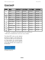
RC5 codes Voxnet 218
[Address] [Command]
Button
*
Name
Code Page 1 *
Code Page 2
Code Page 3
Code Page 4
User 1
[17] [63]
[24] [63]
[25] [63]
[26] [63]
User 2
[20] [63]
[24] [55]
[25] [55]
[26] [55]
Radio
[07] [63]
[24] [56]
[25] [56]
[26] [56]
Disc
[21] [63]
[24] [57]
[25] [57]
[26] [57]
Local input
[19] [63]
[24] [51]
[25] [51]
[26] [51]
Track_down
[**] [33]
[24] [19]
[25] [19]
[26] [19]
Track_up
[**] [32]
[24] [18]
[25] [18]
[26] [18]
Volume_down
[**] [17]
[24] [21]
[25] [21]
[26] [21]
Volume_up
[**] [16]
[24] [20]
[25] [20]
[26] [20]
Power
[**] [12]
[24] [39]
[25] [39]
[26] [39]
Code Page 1 corresponds to the standard RC5 codes of the M series
** RC5 code is combined with the current user / source address
The defined RC5 codes can be checked
through the display on the Voxnet 219.
The infrared mode can be selected with
its Setup button, the received signals
from the IR Link inputs can be detected
and its RC5 address and command can
be displayed.
IR-Display Voxnet 219
25
Voxnet 218
Wall-mounted keypad
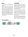
Cabling
Parallel switching
The Voxnet 218 is connected to the
Voxnet 219 over a 3-pin, screwable plug
connector.
In the case of larger rooms it can be
advisable to place two Voxnet 218 wallmounted keypads at two different
locations in the room. Two Voxnet 218s
can be operated in parallel, i.e. all 3
signal cables (GND, IR and VCC) are
connected in parallel.
With the cabling between the Voxnet 219
and the Voxnet 218 wall-mounted
keypad, care must be taken that in the
case of a CAT cable (S/FTP, F/FTP), the
screening is connected to the GND
cable on both sides. In addition, a pair of
cables for one signal should be closed
together. Both these measures raise the
cable cross section and thereby reduce
the voltage drop-off. Cable lengths of up
to 100 metres can be achieved with this
cabling method.
In order to avoid command duplication
when using remote controls, we
recommend deactivating one of the IR
receivers in a Voxnet 218 wall-mounted
keypad. This is done through a DIL
switch (DIL 1) on the rear of the keypad
(please refer also to the next chapter
"Technical data").
The maximum permissible loading on the
IR link, including the Voxnet 219 OUT
trigger, is 80 mA. The nominal power
requirement of one Voxnet 218 is 23 mA.
CAT cable cabling plans
26
Wall-mounted keypad
Voxnet 218
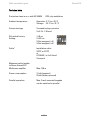
Technical data
Protection class in acc. with IEC 60529
IP20, dry installation
Ambient temperature
Operation -5 °C to +45 °C
Storage: -25 °C to +70 °C
Connection type
Screwable plug connector
3 x 0.15 - 1.50 mm²
DIL switch factory
Setting:
1: IR on
2: LED on
3: Not assigned / off
4: Not assigned / off
Cable1
Installation cable
S/FTP or F/FTP
or
U72 ABG 1 x 4 x 0.5 mm²
Screened
Maximum cable lengths
to Revox Voxnet 219
Multiroom amplifier
Max. 100 m
Power consumption
17 mA (passive) /
23 mA (button pressed)
Parallel operation
Max. 2 wall-mounted keypads
can be switched in parallel
27
Voxnet
Network terminology glossary
NETWORK TERMINOLOGY GLOSSARY
DHCP
DHCP is an abbreviation for Dynamic Host
Configuration Protocol. DHCP is primarily
used to enable clients to fetch their network
configuration automatically from a server or
router. The Voxnet 219 supports DHCP.
DNS
The Domain Name System (DNS) is one of
the most important services in the Internet.
Its main task is that of converting Internet
addresses like www.revox.de for example,
into its corresponding IP address. As a rule,
the router in home networks also fulfils the
function of the DNS. If you should decide for the
manual network configuration (without DHCP).
just enter the address of your router as the
DNS address during network configuration.
Ethernet network
A switch or a router with an integrated
switch ensures the correct connections of
the individual components within a network.
In order to make this possible, each device
within a network must be capable of being
uniquely identified. Each component
therefore, is given its own address, the socalled IP address. The IP address is made up
four blocks of numbers, each of which can
contain up to three digits. These blocks of
numbers are separated by a full stop, e.g
192.168.1.1.
Each of the individual blocks of digits can
have a value between 1 and 254. The values 0
and 255 are in part reserved for special
functions and therefore shouldn't be used. In
order to ensure a secure function of your
network, addresses from a pre-defined range
should be used, i.e. fundamentally, the first
two blocks should be 192.168.xxx.xxx; the
third block can be selected from the values in
the range mentioned above (must be the
same for all the devices within a network
however) and the fourth block should be
used to differentiate each device, e.g.:
Voxnet 219 192.168.001.001
NAS:
192.168.001.002
PC:
192.168.001.003
If you don't just want to use devices within
the local network but also music sources
from the Internet (Internet radio), the client
must have the possibility of being able to
access the Internet. This can be achieved,
for example, through a router with a
connection to a DSL network. This router is
also a part of the network and will be
assigned its own IP address. It must be
ensured that the first three blocks of the
Device IP, the Gateway IP and the DNS 1 are
within the same address range, e.g.
192.168.0.xxx. The fourth block assigns a
unique address ("house number") to the
components in the local network. This
number may only occur once within the local
network. The device IP mask should always
be given the address 255.255.255.0.
Gateway
The computer or router in your network
through which the data traffic with the world
outside your network, i.e. the Internet, is
handled.
IP address
Network address. Each device in the network
needs an IP address through which it can be
reached and uniquely identified. Network
addresses may not occur twice. This is
important if network addresses are assigned
manually. If addresses are issued in your
network through DHCP, you don't need to
worry about the IP address assignment as
the DHCL server automatically handles the
question of address management.
28
Network terminology glossary
Voxnet
LAN
Voxnet IP proxy
Local Area Network – Local cabled network.
A LAN connection is the most fault-tolerant
and problem free transmission technology,
which offers much more security against
eavesdropping than WLANs or Power LANs.
This is a server service in the Voxnet system
that can be used to control third-party
devices through an IP communication, e.g.
with an IP-RS232 converter.
Router (WLAN Router)
MAC Address
The MAC address (Media Access Control) is
the unique hardware address that is used for
the unambiguous identification of the device
in the network.
The MAC address of the Voxnet 219 can be
read out directly from the front display of a
unit that is switched and from the MAC label
on the rear of the amplifier.
NAS
Network Attached Storage. As a rule, this is a
storage device with a very large capacity >
500 GB, which other devices can access.
Power line – LAN
With the power line LAN, data is transmitted
through the existing power cable network.
So-called power line modems are required
on the transmitter and receiver side. As a
rule, power line LANs offer reasonably faultfree data transmission with a data rate
sufficient for audio streaming. We
recommend power line modems with bit
rates of 200 or 200 MBit/s.
Proxy server
General
A proxy or proxy server is a computer in the
network that makes data transfer quicker and
more efficient and that can also increase
security by deploying access control
mechanisms.
29
Central network device that establishes and
manages the communication between the
network devices.
Current devices increasingly combine the
function of the router with the function of an
access
point
for
wireless
data
communication. These combi-devices are
often referred to as WLAN routers. Normally,
the (WLAN) router in a network takes on the
function of the gateway to the outside world.
Server
Network device that makes data and
services available for other devices in the
network. A UPnP-AV server stores for
example, audio and video media data and
makes this data available to other devices,
the streaming clients. Often, UPnP-AV
servers also offer functions for the
cataloguing and easy identification of medial
content according to criteria such as artist,
album name, genre, etc.
Streaming (client)
Network device that draws data out of the
network, decodes it and converts it for
example, into analogue music signals, which
then can be played through amplifiers and
speakers. Streaming clients
also contain functions for displaying media
content and for navigating the Internet or
servers.
Voxnet
Network terminology glossary
UPnP-AV
VLAN
Universal Plug and Play – Audio Video
A Virtual Local Area Network (VLAN) is a
logical network segment within a switch
or within a complete physical network. It
can extend over one or more switches. A
VLAN separates physical networks into
network segmentss by ensuring that
VLAN-capable switches do not forward
the frames (data packets) from one
VLAN to another VLAN, even though the
network segments may be connected to
a common switch.
Network standard that makes media content,
e.g. on PCs or NAS discs accessible in
networks.
A UPnP-AV software must be installed on
PCs /NAS storage so that the clients can
access the stored media data.
Overview of UPnP software:
Windows:
Twonky Media Server
http://www.twonkyvision.de/
Windows Media Player 11
Copyright reference
http://www.microsoft.com/windows/windows
media/de/default.aspx
Explanations and descriptions used in
the "Network terminology glossary"
chapter originate in part or in full from
"Wikipedia - The Free Encyclopaedia".
Mac:
Twonky Media Server for Mac
http://www.twonkyvision.de/
Linux:
Mediatomb
http://mediatomb.cc/
GmediaServer
http://www.gnu.org/software/gmediaserver/
30
Network terminology glossary
Voxnet
APPENDIX
Environmental protection
Warranty
Warranty covers a period of 24 months
from the purchasing date. Your specialist
dealer is your first contact if you need
service help. If he is unable to assist you,
send your device, carriage free, without
accessories to your national Sales
Office.
Please supply a complete description of
the fault together with your address.
Copyright
Voxnet
Voxnet is a registered trademark of
Revox GmbH.
31
Packaging
We recommend keeping the original box
and packaging material so that if
required, the device can be transported
safely.
Voxnet 218/ 219
Please note: The EU Directive
2002/96/EC governs the correct
return, handling and recycling
of used electronic devices. For this
reason, electronic used devices must be
disposed of separately. This device
should not be disposed of with normal
domestic waste. You can take your used
device to recognised disposal points.
You can get further information about
the return of such devices from your
local authority, also in non-EU countries.
Voxnet
Appendix
Voxnet 218 + 219 Operating manual
32