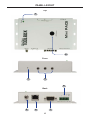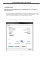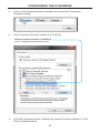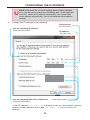
1
Mini PACS
GTB-MINI-PACS
User Manual
www.gefentoolbox.com
ASKING FOR ASSISTANCE
Technical Support:
Telephone
(818) 772-9100
(800) 545-6900
Fax
(818) 772-9120
Technical Support Hours:
8:00 AM to 5:00 PM Monday through Friday, Pacific Time
Write To:
Gefen, LLC
c/o Customer Service
20600 Nordhoff St
Chatsworth, CA 91311
www.gefentoolbox.com
[email protected]
Notice
Gefen, LLC reserves the right to make changes in the hardware, packaging and
any accompanying documentation without prior written notice.
Mini PACS is a trademark of Gefen, LLC
All trademarks are the property of their respective companies.
© 2012 Gefen, LLC, All Rights Reserved
All trademarks are the property of their respective companies
Rev A2
1.11
CONTENTS
1
2
3
4
5
6
6
7
12
12
13
14
15
17
22
26
30
32
33
33
35
36
37
39
41
43
43
56
63
74
77
77
78
80
81
Introduction
Operation Notes
Features
Panel Layout
Panel Descriptions
Connecting the Mini PACS
Wiring Diagram
Configuring the IP Address
Web Interface
The Built-in Web Server
RS-232 Menu
RS-232 Settings
TCP / UDP Bridge Settings
IR Emitters Menu
Adding a new IR device
Adding a new IR device from a Template
Relays Menu
Testing Relays
Configuration Menu
IP Configuration
Telnet Login Settings
Firmware Update
System Reset
System Settings
IP (Telnet) Control Setup
RS-232 / Telnet Commands
IP Configuration
Bridging Settings
IR Device Setup
General Query
Appendix
Controlling the Mini PACS via RS-232
Learning IR Commands via Telnet
Specifications
Warranty
INTRODUCTION
Congratulations on your purchase of the Mini Professional Automation Control
System. Your complete satisfaction is very important to us.
Gefen
Gefen delivers innovative, progressive computer and electronics add-on solutions
that harness integration, extension, distribution and conversion technologies.
Gefen’s reliable, plug-and-play products supplement cross-platform computer
systems, professional audio/video environments and HDTV systems of all sizes
with hard-working solutions that are easy to implement and simple to operate.
The GefenToolBox Mini Professional Automation Control System
The Mini Professional Automation Control System (Mini PACS) is used to
control audio and video devices (such as TVs, Blu-ray players, and set-top
boxes) over a network. It allows control of one RS-232 serial-controlled device,
three IR-controlled devices, and two relay contacts via IP over a network.
The Mini PACS is a scaled-down version of the PACS, providing the
same level of control, but has fewer Input and Output ports. This makes it more
cost-effective for distributed control installations, or where fewer I/O ports are
required.
The Web user interface allows IR and two-way RS-232 commands to be sent
by the Mini PACS to the connected devices to execute the desired functions.
The IR and RS-232 ports can be configured, allowing the Mini PACS to be
compatible with most audio and video devices. It can learn, store, and manage
IR commands from other manufacturers’ remotes. Two normally-open relays
allow control of screens, blinds, or draperies.
The Mini PACS is ideally suited for use with the GAVA, Gefen’s (Audio/Video
Automation) System Processor. However, it can be used with other control
systems capable of IP communications. And, like all GefenToolBox products,
the Mini PACS can be mounted on a wall or any flat surface, close to the
devices being controlled.
How It Works
Connect the locking power supply to the Mini PACS. Connect an Ethernet cable
between the Mini PACS and the local network. Access the Web interface by
typing in the correct IP address on the Web browser. Configure the control
interfaces (IR, RS-232, and relays) via your Web browser. Configure your
automation system to send commands to the Mini PACS via IP. Connect a
serial-controlled device to the RS-232 port on the Mini PACS. Plug the IR
emitters into the Mini PACS and place the infrared LEDs close to the IR sensors
of the A/V devices to be controlled via IR. Connect to the relay outputs as
required (12V DC is also provided for convenience). Two-way RS-232 control
allows device feedback to be returned to the control system over the network for
accurate control.
1
OPERATION NOTES
READ THESE NOTES BEFORE INSTALLING OR OPERATING
THE PROFESSIONAL AUTOMATION CONTROL SYSTEM
•
The Mini PACS is shipped with a static IP address of 192.168.1.72. This
address may need to be changed before the Mini PACS will work on your
Local Area Network. See page 7 for instructions on setting the Mini PACS to
a new IP address.
•
If your network will contain multiple Mini PACS and/or PACS units, each one
must have a unique IP address before it is connected to the network. Install
one Mini PACS at a time, and change its IP address before connecting
another Mini PACS or PACS to the network.
•
As the Mini PACS is programmed, you can download the configuration and
IR files to your computer or an external storage device. We recommend that
you back up files frequently during programming, and save IR files for each
device as it is learned. These files can be transferred to another Mini PACS
or PACS for future projects.
•
RS-232 commands are not stored in the Mini PACS. Only the configuration
data is stored. The Mini PACS acts as a bridge between your controller that
is sending the RS-232 commands over your network, and the actual RS-232
port on the device that is being controlled.
•
Mini PACS allows control to be distributed throughout your system. Multiple
Mini PACS devices may be installed close to the devices being controlled,
rather than near the system controller, to minimize cabling and improve
reliability.
RS-232 Port Wiring Diagram
54321
12345
9876
6789
Only Pins 2 (RX), 3 (TX), and 5 (Ground) are used on the RS-232 serial interface
2
FEATURES
Features
•
Control A/V devices using IR, RS-232 control, and relays over a Web-based
IP control system
•
Configurable Ethernet input supports Telnet, Web browsers, and TCP/IP
•
Web Control: User interface designed to be viewed and controlled by home
automation devices, computers, and mobile devices (e.g. cell phones with
Internet browsers)
•
Two (2) NO (Normally Open) relay outputs plus +12V DC @ 1A and Ground
for convenience
•
Learns IR commands from manufacturer remotes, through front-panel IR
receiver
•
Three (3) discrete IR emitter outputs for multiple device control
•
Store and manage IR commands from manufacturer remotes and access
them via the Web control interface. IR commands may be uploaded from or
downloaded to online libraries or PC files.
•
Mini PACS IR files are compatible with the Gefen PACS
•
Manage RS-232 communications via Web control interface for one RS-232
device
•
Supports data transfer rates up to 115200 baud
•
Firmware upgradeable via Web interface
•
Configurable static IP address for stable operation
•
Wall-mountable
Package Includes
(1) Mini Professional Automation Control System
(1) Single IR emitter
(1) 6 ft. DB-9 cable (M - F)
(1) 12V / 3A DC Locking Power Supply
(1) Quick Start Guide
3
PANEL LAYOUT
Top
1
2
Front
3
4
8
Back
5
6
7
4
PANEL DESCRIPTIONS
1
Power
This LED will indicate the current power state. The LED is green when the unit
is powered ON.
2
IR Sensor
The IR receiver is provided for the Mini PACS to learn new IR commands. Use
the Web Interface or Telnet for this procedure. See pages 17 - 29 for more
information.
3
IP Reset
This button is placed beneath the enclosure surface to prevent an accidental
reset. Use the end of a paperclip to press and hold this button for about 10
seconds to reset the unit’s IP address to 192.168.1.72. This should only be
done if the Mini PACS is moved to a new network or cannot be located on the
network.
4
IR Emitters
Connect up to three (3) single or dual 12V IR emitters (Gefen part nos.
EXT-IREMIT / EXT-2IREMIT or other Xantech-compatible emitters) to these
ports to control A/V of other devices using one-way IR control. These outputs
are capable of transmitter IR signals with 30 - 60 kHz carrier frequencies.
5
12V DC
Connect the included 12V DC locking power supply to this receptacle.
6
IP Control
Connect the Mini PACS to a network in order to use IP control.
7
RS-232
This ports is used to control other devices via bi-directional RS-232 serial
control, using TCP or UDP bridging. This port may also be used with a Terminal
Emulation program for programming and controlling the Mini PACS (See
Appendix for details).
NOTE: Only pins 2 (Receive), 3 (Transmit), and 5 (Ground) are used
for communication. A null-modem adapter should nott be used with
this product when connecting to controlled devices (see page 77 for
connecting to a computer via RS-232).
8
Relay Contacts
Two (2) NO relay contacts with +12V DC and Ground. The maximum current
draw from the 12V is 100 mA.
5
CONNECTING THE MINI PACS
How to Connect the Mini PACS
1.
Connect the included RS-232 cable between the Mini PACS and the RS-232
device.
2.
Connect up to three (3) single or dual IR Emitters to the Mini PACS. Make
sure that each LED emitter is close to the IR sensor of the A/V devices to be
controlled.
3.
Connect the relay leads from the control motors of projection screens, blinds,
or draperies to the relay outputs on the back panel of the Mini PACS.
4.
Connect an Ethernet cable between the Mini PACS and the network. See the
next page for details on configuring the network.
5.
Connect the included 12V DC power supply to the power receptacle on the
Mini PACS. Connect the AC power cord to an available electrical outlet.
Wiring Diagram for the Mini PACS
RS-232
ETHERNET
IR
12V/GND TRIGGERS
Network
Projector
Set Top Box
12V/GND Triggers
GAVA Control System
Mini-PACS
Blu-ray Player
Powered Screen /
Curtains
GTB-HDFST-444
GTB-MINI-PACS
6
CONFIGURING THE IP ADDRESS
Setting the IP Address
The Mini PACS is designed to control devices over a network using a built-in
Web server or via Telnet. Before using Telnet control or the built-in Web Server,
the network settings for the Mini PACS must be configured via IP.
Before connecting the Mini PACS to a network, locate the label on the bottom
of the Mini PACS. The MAC address and the default IP address will be listed on
the label. The default IP address will be used to connect the Mini PACS to the
network.
IMPORTANT: Because all Mini PACS and PACS units have the
same default IP address, only one Mini PACS or PACS may be
connected to a network at a time, until its IP address is changed. If
more than one device with the same IP address is connected to a
network, computers will be unable to locate any of the devices.
MAC Address
Primary MAC address of the Mini PACS.
This address is different for each unit and
cannot be changed.
7
CONFIGURING THE IP ADDRESS
If you computer has an IP address of 192.168.1.(x), and 192.168.1.72 is
an available address, you can access the Mini PACS by entering 192.168.1.72
in your Web browser.
Otherwise use the following procedure to change the Mini PACS IP address to
match your network:
1.
Access the Network Setting control panel in Windows and locate your LAN
connection. Under Windows 7®, this can be done by clicking Start > Control
Panel > Network Sharing Center > Change Adapter Settings.
2.
Click on the Local Area Connection icon to display the Local Area
Connection Status dialog:
8
CONFIGURING THE IP ADDRESS
3.
Click on the Properties button to display the Local Area Connection
Properties dialog.
4.
Click on Internet Protocol Version 4 (TCP/IPv4).
Internet Protocol Version 4 (TCP/IPv4)
Click to highlight this Network protocol.
5.
Click the Properties button to display the Internet Protocol Version 4 (TCP/
IPv4) Properties dialog.
9
CONFIGURING THE IP ADDRESS
STOP: Write down the current IP settings before making changes,
since you will need to restore the old settings later. If the Properties
are set to “Obtain an IP address automatically” and “Obtain DNS
server address automatically”, you do not need the actual address
settings.
6.
Change the IP settings to the following:
Subnet mask
255.255.255.0
Use the following IP address
Click this radio button.
IP address
192.168.1.80*
Use the following DNS server addresses
Click this radio button.
Clear these boxes.
*If the IP address 192.168.1.80 is already in use on your network, choose
another unused address that is not 192.168.1.72 or your router’s IP
address
10
CONFIGURING THE IP ADDRESS
7.
Click the OK button, then close all Control Panel windows.
8.
Refresh your Web browser and go to http://192.168.1.72 to open the
Mini PACS Web Server.
9.
Go to the Configuration Menu (see page 33) and change the Mini PACS IP
address to an appropriate address for your network.
10. Click ”Save Changes”, “Reboot”, and “OK” to save the new IP address.
11. Reopen your computer’s network settings and restore the original settings
(or go back to “Obtain an IP address automatically” and “Obtain DNS server
address automatically”, if those were the original settings).
12. Then refresh your Web browser and go to the new Mini PACS IP address to
reopen the Mini PACS Web Server.
Repeat this procedure to add additional Mini PACS units to your network,
assigning each unit a different IP address.
11
WEB INTERFACE
The Built-in Web Server
The Mini PACS includes a built-in Web server which provides an intuitive Web
interface. If TCP/IP is not configured on the Mini PACS, then see page 7 for
details on configuring the Mini PACS. If the Mini PACS is already configured for
use on a network, then open a Web browser and type in the IP address of the
Mini PACS.
The built-in Web server provides control over RS-232, IR emitters, relays, and
general configuration. Each of these pages will be covered in the following
sections.
Initially, when the Web page is launched, the RS-232 Menu is displayed. The
top portion of the screen has tabs to select RS-232 settings, IR settings, relay
settings, general configuration. Click on the desired tab to bring up the settings
page for those functions.
Main Menu
Click on any of the four menu
selections to access the desired page.
Reboot
The Mini PACS must be rebooted after
making all changes.
12
WEB INTERFACE
RS-232 Menu
The RS-232 Menu allows you to change the RS-232 port settings on the Mini
PACS.
Description
Provide a name to the device
connected to this port
(e.g. “SonyTV”, “Samsung”, etc.)
13
WEB INTERFACE
RS-232 Settings
Some RS-232 settings use a drop-down menu for selecting different options.
For example, to select the Baud Rate, click the arrow icon then click on the
required port speed:
Arrow Icon
Indicates a dropdown list. Click to
list the available
baud rates.
Baud Rate
Sets the baud rate for the port.
Range: [100 bps - 115200 bps]
Parity
Sets the parity bit.
Options: Even, Odd,
None, Mark, Space
Stop Bits
Sets the stop bit.
Range: [1 - 2]
Line Delay (ms)
Range: [0 - 10000]
Character Delay (ms)
Not used.
Data Bits
Sets the number of data bits.
Range: [5 - 8]
UART Mode
Options: TCP Bridge,
UDP Bridge
14
WEB INTERFACE
TCP / UDP Bridging Settings
UDP Protocol is used by some control systems, including Gefen’s GAVA system,
for faster response. When using UDP you can broadcast the message by using
the IP address: 255.255.255.255. Use TCP unless otherwise instructed by your
Control System User Manual, or by Gefen Technical Support. See page 56 for a
full explanation of these settings.
Force Send (bytes)
If the specified number of bytes is received from the controlled device, send
the collected data to the control system.
Force Send (ms)
If no data is received from the controlled
device for the specified time, send the
collected data to the control system.
Use End Delimiter
Options: Use
(Enable / Disable)
End Delimiter
Value in HEX
Range: Same
as Start Delimiter
Use Start Delimiter
Options: Use (Enable / Disable)
Add Delimiters to data sent
Include the delimiter characters in the data sent to the control system.
15
WEB INTERFACE
TCP / UDP Bridging Settings
Start Delimiter Value
Range: 00 - FF (“wildcard” characters are acceptable, e.g. **)
The Start Delimiter can be up to three ASCII characters (3 bytes), in hex
format. For example, 0D0A is CR + LF (Carriage Return + Line Feed).
The delimiters are used by some control systems to filter incoming data.
Contact Gefen Technical Support for details if you need to use them.
TCP Port
Range: 0 - 65535
UDP Remote IP
Factory Default
Sets the selected
RS-232 port to factory
(default) settings.
Save Changes
Saves all changes to the
selected RS-232 port. This
button must be pressed after
changing each output setting. in
order to save any changes.
UDP Remote Port
Range: 1024 - 65535
UDP Local Port
Range: 1024 - 65535
16
WEB INTERFACE
IR Emitters Menu
The Mini PACS has three (3) IR Emitter (IR back-channel) ports. The Mini PACS
can use any one of these IR Emitter ports to send IR commands to the source
device. Up to 64 IR commands can be stored per device. IR configuration files
can be saved, downloaded, uploaded, edited, and deleted.
Select Outputs To Test Commands
List of IR Emitter output
p p
ports used to test the IR commands.
Select Device
List of devices which have
been stored in the PACS.
The PACS can store up to 20
devices.
Rename Device
Renames the currently selected
device in the list.
Add D
Device
i
Adds a device to the list. This
action must be performed before
learning a device.
D l t Current
Delete
C
Device
Deletes the currently selected
device from the list.
17
WEB INTERFACE
Command Name
Used to enter / edit the name of each
IR command. This is a required field.
Up to sixty-four (64) IR commands can be
stored per device. Each Command Name
can be up to 20 Alphanumeric characters
or spaces.
Advanced View
Click this link to toggle between
Basic View and Advanced
View.
18
Test
Press the Test button to
validate the learned IR
command. One or more
outputs must be selected and
an IR Emitter plugged in before
test can be sent.
WEB INTERFACE
Learn All
Performs a “stepthrough” when learning
IR commands from a
template (see page
26).
Advanced View
Click the Advanced View link
to display additional options
for learning or deleting IR commands.
Learn
Click the Learn button to learn a
new IR command (see page 22).
Delete
Click the Delete button to delete
a learned IR command. Deleted
commands will be permanently
removed after saving changes.
19
WEB INTERFACE
Model No. (optional)
This is the device model number (e.g. KDL40EX729, etc.)
This field is used by the GAVA to sort the IR library.
Max. Length: 10 characters (no dashes, slashes, etc).
Manufacturer (optional)
This is the device manufacturer’s name (e.g. Sony,
Yamaha, etc). This field is used by the GAVA to sort to the
IR library. Max. Length: 10 characters
Class (optional)
This is the generic class of the device: Display, Disc, AVR
(A/V Receiver), or STB (Set-Top Box). This field is used
by the GAVA to select the proper control template.
Max. Length: 10 characters
Name
This is the Device Name of the currently-displayed Device.
It is case-sensitive. You cannot edit the name. If you
change it, then a new device will be added.
20
WEB INTERFACE
Bro
owse...
Click this button to open a list of files on
your computer to Upload. It will open the
last selected folder on your computer with a
default selection of All Files (*.*).
Download IR File to PC
Press this button to save the currently-displayed Device IR
commands to an XML file on your computer. Choose a folder
location and filename that will allow you to easily locate the file at a
later time.
Save Changes
Press this button to save any changes to the currently-displayed Device.
Be sure to press “Save Changes” before navigating away from this page
or selecting another Device, or your changes will be lost
Device ID
The Mini PACS assigns an internal number to each Device in memory.
You can use this number to keep track of the number of Devices you
have stored in the Mini PACS.
21
WEB INTERFACE
Adding a new IR Device
The Mini PACS can hold up to 20 IR devices in memory. Each device may have
up to 64 Commands. If you are building a library, you may need to delete some
devices from the Mini PACS once they are learned and saved, to make room for
more devices. However, if you have several of the same devices with separate
IR emitters, you can use the same IR “Device Name” for all of them, but specify a
different output for each one when you send the commands.
Be sure to “Save Changes” after learning any new commands before navigating
away from the learning page.
1.
Press “Add Device” button on Mini PACS IR Emitters page.
2.
If you have an existing Iearned IR code file, or wish to download an empty
Command Name template for the new device, click the “Browse” button, and
navigate to the location on your computer where the IR files and templates
are located. Select the desired “*.gfn” file and click “Open”. Otherwise, skip
to Step 8.
3.
Enter a Name for the new device. The name can be up to 20 characters
long, and will be used to identify the device for sending IR commands.
4.
Enter the Class, Manufacturer, and Model Number of the device (optional).
5.
Click “Save Changes” to store the file
6.
Select the stored device from the “****Select Device ****” pull-down menu.
7.
If the IR commands were already learned for that device, the Command
Names will be green, and the commands may be tested by installing an IR
Emitter in front of the device’s IR window, connecting the emitter to an IR
Output port on the Mini PACS, selecting that Output in the Web browser,
and clicking on the “Test” button for that command. Verify that the device
responds as expected.
8.
If a blank template was stored for that device, the Command Names will
appear, but they will be yellow, rather than green. This means that only
the names, and not the IR data, have been stored. See “Adding a New IR
Device from a Template” on page 26.
9.
If you are starting a new device file, the Command Names will be empty, and
the fields will be light blue. Click on the first empty Command Name window,
and enter a name for the command (note that only letters, numbers, and
spaces can be entered. Spaces will be replaced with underscores when the
file is saved). The Command Name and Device Name are case-sensitive.
10. Click on the “Advanced View” button above the Command Name list. This
adds the “Learn” and “Delete” buttons for each Command.
22
WEB INTERFACE
10. Find the IR remote for the new device. Make sure the batteries are fresh!
Hold the remote so it is pointing at the IR window on the Mini PACS, and is
about 6” away from the window.
11. Click the “Learn” button for the first named Command.
12. You will be prompted to press the remote button that matches the Command
Name you are learning. Press the button firmly- do not hold it down, or just
hit it quickly.
Learning IR MODE Enabled:
Please have your remote control and get ready to press the remote key...
Please press the 1 button.
Please press the 1 button again.
13. You will be prompted to press the same button a second time. The Mini
PACS will confirm that the two codes match. Some IR remotes use “toggle
codes”, where the IR code toggles between two different codes each time
the button is pressed. The Mini PACS will recognize this, and ask you to
press the button a third and fourth time.
Learning IR MODE Enabled:
Please have your remote control and get ready to press the remote key...
Please press the 4 button.
Please press the 4 button again.
1st and 2nd command captures were not identical, please press the 4 button
with your remote.
Please press the 4 button again.
23
WEB INTERFACE
14. If the commands match, the Mini PACS will return to the main screen, and
the new command will now be green.
15. If a code is learned incorrectly, you may overwrite it by repeating steps 11 13. The Mini PACS will warn you that the command is already in memory,
and ask you to confirm that you want to overwrite the existing code. Press
“OK” to do so. Once a Command is learned, its Command Name may not
be changed. If the name is incorrect, you must delete the Command Name,
and add a new command and re-learn the code.
ADVANCED: If you are familiar with editing XML files, you can
download the Config file, edit the XML file, and upload it again to the
Mini PACS. This is an advanced feature and not recommended for
new users.
16. Learn each command in turn by repeating the “Learn” procedure (after
entering each Command Name if necessary).
17. Press “Test” to verify that each command performs as expected (see
Step 6).
18. Press “Save Changes” to save the learned Commands to the Mini PACS.
Be sure to do this before navigating away from the page, or the changes
will be lost! You can leave the page after saving changes, and return later
to learn new commands, or test/modify existing commands. All named
commands must be learned before saving the changes. Command names
that do not contain IR data will be deleted when changes are saved.
19. Once a new device has been learned, you should download the new device
IR file to your computer and save it. Press the “Download IR File” button to
do this.
20. Mini PACS will prompt to “Open” or “Save” the file. You probably should
click “Open” to see and check the file before saving it. A sample XML file is
shown on the next page.
24
WEB INTERFACE
<?xml version=”1.0” encoding=”UTF-8”?>
<ir_emitter>
<dn>Bedroom_DVD</dn>
<class>Disc</class>
<manufacturer>Sony</manufacturer>
<model>BDPS580</model>
<cs>
<c>
<cn>power_toggle</cn>
<freq>1175</freq>
<p_len>64</p_len>
<p_dat>564 149 279 ... 149 137 5149 0</p_dat>
<p_rep>1</p_rep>
</c>
<c>
<cn>power_off</cn>
<freq>1200</freq>
<p_len>64</p_len>
<p_dat>564 148 280 ... 136 5007 0</p_dat>
<p_rep>1</p_rep>
</c>
<c>
<cn>volume_up</cn>
<freq>1200</freq>
<p_len>64</p_len>
<p_dat>564 148 137 ... 137 5291 0</p_dat>
<p_rep>1</p_rep>
</c>
</cs>
</ir_emitter>
NOTE: The series of numbers contained within the opening and
closing <p_dat> tags have been abbreviated due to limited page
space.
21. Verify that the commands contain data, and click “File > Save as . . .”,
and enter a location and filename for the new file. Do not use the default
“ir_emitter_xml.xml” filename, as it will overwrite earlier stored files. We
recommend that you use a filename that contains the manufacturer name
and model number of the device, so you can easily identify the file later.
The maximum filename size is 25 characters.
22. Press “Save” to actually save the file to your computer
23. Repeat the above procedure for each device you wish to add to the Mini
PACS.
25
WEB INTERFACE
Adding a new IR device from a Template
Templates are useful when you want to ensure that similar commands for
different product models have identical Command Names. This will simplify the
process of programming your control system, and allow you to replace one disc
player, for example, with another model, without having to change the control
system programming.
Gefen’s GAVA Control System requires that IR commands have specific name
conventions that are matched to the GAVA User Interface buttons, so Templates
provide an easy way to ensure that new devices have the proper names.
Using a Template also allows you to just push buttons on your IR remote as
prompted, without having to simultaneously enter names and navigate the screen
on your computer.
Mini PACS has several pre-configured templates for the Gefen GAVA control
system, available from the Gefen Web site, which are needed to build a GAVA
Library. These correspond to the different Classes of IR-controlled devices:
Template
Definition
avr
Audio/Video Receiver or Amplifier
display
Display, TV, Projector, or Monitor
disc
Disc Player (Blu-ray, DVD, CD, Music Server)
stb
Set-Top Box (Cable or Satellite Receiver)
To add a new device, using a Mini PACS Template File:
1.
Press “Add Device” button on Mini PACS IR Emitters page.
2.
Enter a Name for the new device. The name can be up to 20 characters
long, and will be used to identify the device for sending IR commands.
3.
Optionally, enter the device Manufacturer and Model Number.
4.
Click the “Browse” button, and navigate to the location on your computer
where the IR templates are located. Select the desired “*.gft” file and click
“Open”.
5.
Click “Save Changes” to store the file.
6.
Select the stored device from the “****Select Device ****” pull-down menu.
26
WEB INTERFACE
6.
Since this is a template file, the Command Names will be yellow, rather than
green. This means that only the names, and not the IR data, have been
stored.
7.
Click on the “Advanced View” button above the Command Name list. This
adds the “Learn” and “Delete” buttons for each Command, and a button
named “Learn ALL” above.
8.
Find the IR remote for the new device. Make sure the batteries are fresh!
Hold the remote so it is pointing at the “IR” window on the Mini PACS, and is
about 6” away from the window.
9.
Click the “Learn ALL” button.
10. You will be prompted to press the remote button that matches the Command
Name you are learning. Press the button firmly- do not hold it down, or just
hit it quickly.
11. You will be prompted to press the same button a second time. The Mini
PACS will confirm that the two codes match. Some IR remotes use “toggle
codes”, where the IR code toggles between two different codes each time
the button is pressed. The Mini PACS will recognize this, and ask you to
press the button a third and fourth time.
27
WEB INTERFACE
12. If the commands match, the Mini PACS will prompt you for the next
Command in the list.
13. If you are prompted for a command that does not exist on your remote,
you can press the “SKIP Command” button, and you will be prompted for
the next button on the list, or you can press “EXIT IR Learning” to end the
process. If you start the Learn ALL process again, it will start with the first
un-learned command, and skip any commands that have previously been
learned.
AUTO IR Learning MODE Enabled:
Please have your remote control and get ready to press the remote key for 3
Please press the 3 button.
14. Learn each command in turn until all have been learned.
15. The learned command will now be green. Any commands that were skipped
or not learned successfully will still be yellow.
16. You can manually add any commands that were not in the template
afterwards. Since commands are accessed by name, and not by number,
the sequence of learning commands is not critical. Commands that are
in the Template cannot be re-named. They can be deleted, and then new
commands may be added at the bottom after saving the changes. There is
a maximum of 64 commands per device, so you may need to delete some
unused commands to create room for any new ones.
17. Press “Test” to verify that each command performs as expected.
28
WEB INTERFACE
18. You can delete any commands that are not available for that specific remote
by clicking the “Delete” button for those commands. Deleted buttons will be
removed when changes are saved. Un-learned template commands will be
saved for later learning.
19. Press “Save Changes” to save the learned Commands to the Mini PACS.
Be sure to do this before navigating away from the page, or the changes will
be lost! You can leave the page after saving changes, and return later to
learn new commands, or test/modify existing commands.
20. Once a new device has been learned, you should click the “Download
IR File to PC” button to download and save the new device IR file to your
computer.
21. Mini PACS will prompt to “Open” or “Save” the file. You probably should
click “Open” to see and check the file before saving it.
22. Verify that the commands contain data, and click “File > Save as . . .”,
and enter a location and filename for the new file. Do not use the default
“ir_emitter_xml.xml” filename, as it will overwrite earlier stored files. We
recommend that you use a filename that contains the manufacturer name
and model number of the device, so you can easily identify the file later.
23. Press “Save” to actually save the file to your computer.
24. Repeat the above procedure for each device you wish to add to the Mini
PACS.
IMPORTANT: Be sure to “Save Changes” after learning any new
commands before navigating away from the learning page.
NOTE: The Mini PACS and PACS both use the same IR files and
format. IR files may be transferred between the Mini PACS and
PACS.
29
WEB INTERFACE
Relays Menu
The Mini PACS provides two Normally-Open (NO) relays which can be used for
controlling lighting systems, curtains, motorized screens, or various other automation
devices. Each relay contact is rated for 1A at 30V DC. +12V DC and Ground are
also provided for convenience.
Relay Buttons
Click one of these buttons to name and
configure a relay.
When a relay has been associated to
a specific event, the event will appear
under Devices. See the next page for
information on naming an event.
30
WEB INTERFACE
Save Changes
Saves the trigger
event.
Delete
Deletes the trigger
name and resets
settings to default.
Pulse Duration (ms)
Required when Type
is set to Pulse.
Range: 0 -10000.
(1000 = 1 sec.)
Default State
Sets the default state
of the trigger. Options:
Open, Close.
Device Name
Enter the name of the device
associated with this trigger.
31
Type
Sets the type of relay trigger.
If set to Pulse, the Pulse
Duration (ms) must be
specified. Level stays at the
new state until changed.
WEB INTERFACE
Testing Relays
Press the “Set Closed” or “Set Open” buttons to manually change the state of a
relay. If the “Type” is set to “Pulse”, the relay will revert to its default state after
the Pulse Duration period has expired.
Relay ID
Relay 1 and Relay 2
Relay State
Indicates the current state of the relay. If the
relay is open, then Open is displayed in red.
If the relay is closed, then Closed displayed in
green. Press the Set Close or Set Open button
to change the current state of a relay. By
default, each relay is open.
32
WEB INTERFACE
Configuration Menu
The Configuration Menu allows management of TCP/IP configuration, login
credentials, firmware upgrades, and system resets.
IP Configuration
IP Address
Sets the IP address.
This must be a valid and
unused address on your
local network.
Maximum value for each
number is 255.
MAC Address
The MAC address cannot be
changed.
NOTE: The top row (Current) indicates the current settings. The
second row (Default) indicates the default settings. The default
settings cannot be changed.
33
WEB INTERFACE
Subnet
Sets the subnet mask.
The default settings is
255.255.255.0
Gateway
Sets the IP address of
your router (IP gateway).
Maximum value for each
number is 255.
Web UI Port
Sets the HTTP listening
port. The default setting
is 80.
Refresh
Refreshes the IP
configuration to obtain
the latest changes.
Telnet Port
Sets the Telnet listening
port. The default port
setting is 23.
Factory Default
Sets the IP Configuration
settings to factory
(default) settings.
34
Save Changes
Saves the current
changes to the IP
Configuration settings.
WEB INTERFACE
Telnet Login Settings
Force Password on Connect
Forces password prompt when
connecting via Telnet.
Display Welcome Message on Connect
Displays a “Welcome to PACS Telnet
Server” message when Telnet connection
opens.
Save Changes
Saves the current changes to the Telnet Login Settings.
Password
Sets the password. Maximum password length is 20
characters. The password is case-sensitive.
UserName
Sets the user name. Maximum user name length is 20
characters. The user name is case-sensitive.
35
WEB INTERFACE
Firmware Update
Get Firmware
Checks the Gefen Web site for the latest firmware. The current version of
firmware is displayed above this button.
Browse...
Click the Browse... button to select the
firmware file after it has been downloaded.
Update
Click the Update button
after the firmware file has
been selected using the
Browse... button.
Reboot
Reboot the PACS after making any configuration changes.
36
WEB INTERFACE
System Reset
Yes To All
Check this box to perform a
System-Wide Reset during a
reset procedure.
Set Triggers To default
Place a check mark in this box to set
triggers to default settings when resetting
the PACS.
ATTENTION: A System-Wide Reset will delete alll Commands and
Device data, reset the IP address, and reset the PACS to factory
(default) settings.
WARNING: Your IP connection will be dropped if you change the IP
address. You must reset your computer to communicate with the
new IP address and then reopen your Web browser and go to the
new address.
37
WEB INTERFACE
Delete IR Commands
Place a check mark in the
box to delete all learned IR
commands during a reset.
Delete IR Devices & Commands
Place a check mark in the box to delete
all IR devices and learned IR commands
during a reset.
Delete IR Commands
Place a check mark in the box to set the
serial ports to their default settings.
38
WEB INTERFACE
System Settings
The System Settings section allows you to upload or restore a file containing
all of the IP settings, RS-232 settings, trigger settings, and all IR files, devices,
and commands. The default name of this XML file is “Settings_xml.gfn”.
This file may be copied to another Mini PACS, which will then be an exact
duplicate of the source Mini PACS (please note that you will have to change the
IP address of the duplicate Mini PACS if both units will be connected to the same
network).
Browse...
Click the Browse... button
to select the settings file to
upload.
Update
Click the Update button to
upload the settings file to
the Mini PACS.
Download
Saves the Mini PACS
settings to a file on your
computer.
39
WEB INTERFACE
It is important to understand that this XML file does not actually exist in the Mini
PACS. Rather, it is created “on-the-fly” by the Web GUI when it is downloaded.
When a new settings file is presented for an update, it is parsed by the Mini
PACS firmware, and the data is stored in the appropriate locations in the Mini
PACS memory.
When a new settings file is uploaded, any new data is added to the existing
data in the Mini PACS, and if there are conflicts, the new data will overwrite the
existing data.
For example, if the Mini PACS has an IR device named “TV” that has a
“power_toggle” command, and a new device is uploaded that is also
named “TV”, but has “power_on” and “power_off” commands instead of the
“power_toggle” command, the Mini PACS IR file will now have the new power on/
off commands, but the old “power_toggle” button from the old device will remain,
since it was not overwritten.
Therefore, if you are replacing old IR files with new ones, you should delete the
old devices before adding the new ones.
IMPORTANT: The Mini PACS settings files are not compatible with
the PACS settings files. Only the IR files are compatible between
the Mini PACS and the PACS.
40
IP (TELNET) CONTROL SETUP
The Mini PACS may be manually operated using the Web server Graphical User
Interface (GUI), or by an automation system (such as the Gefen GAVA System)
that is capable of sending Telnet serial commands to the Mini PACS via IP.
The Web interface allows setting RS-232 communications parameters.
RS-232 device commands are not stored in the Mini PACS, and cannot be sent
through the Web interface. The Mini PACS serves only as an IP-to-RS-232
bridge, allowing a control system to communicate with a remote device through
its network connection to the Mini PACS, instead of through a dedicated serial
connection.
To send RS-232 commands to the Mini PACS, the control system needs to
communicate with the IP address of the Mini PACS (Default is 192.168.1.72- see
page 7 to change the IP address), and the TCP Port Number that is associated
with the RS-232 Port. The Port Number is set in the RS-232 menu in the Web
page. The default TCP Port setting for the RS-232 port is 49202.
RS-232 parameters must also be set to match the requirements of the device
being connected. The user manual for the device should list the proper RS-232
settings. Note that “handshaking” or “flow control” for the connected device must
be set to “None”, as Mini PACS does not support hardware or XON/XOFF flow
control.
For example, to control a Gefen 4x1 HD Switcher (GTV-AUDDEC-N) connected
to the RS-232 port:
1.
Open the Mini PACS Web interface, and click on the RS-232 Tab.
2.
Enter the following settings:
Description
Gefen 4x1 HD Switcher
Baud Rate
19200
Data Bits
8
Parity
None
Stop Bits
1
Line Delay
0
UART Mode
TCP Bridge
TCP Port
49200 (default)
41
IP (TELNET) CONTROL SETUP
3.
Click “Save Settings”.
4.
Open HyperTerminal or another Terminal Emulation program on your
computer.
5.
Open a new session with a Host Address that matches the IP address of the
Mini PACS, and set the Port Number to 49202.
6.
Type “help ?” in the terminal window, and a list of commands from
the AUDDEC-N should scroll in the window, indicating successful
communication with the AUDDEC-N.
Once communications are verified, your control system should be able to connect
to the Mini PACS using the same IP address and Port Number, send commands,
and receive feedback from the connected device.
IMPORTANT: When sending RS-232 commands, a carriage return
and a line feed character must be included at the end of each line.
Telnet Commands, Device Names, and Command Names are all
case-sensitive.
42
RS-232 / TELNET COMMANDS
IP Configuration
Command
Description
#change_relay_state
Changes the current relay state
#display_telnet_welcome
Set Telnet welcome message on login
#load_relay_params
Loads relay parameters from memory
#save_relay_params
Saves relay parameters to memory
#set_http_port
Sets the Web server listening port
#set_pass
Prompts for password when using Telnet
#set_relay_params
Sets the relay parameters
#set_serial_mode
Sets the specified serial port mode
#set_serial_params
Sets the serial port parameters
#set_telnet_port
Sets the Telnet listening port
#set_user_name
Sets the user name for the login procedure
#sgateway
Sets the IP gateway address
#show_pass
Prompts for password when using Telnet
#show_relay_params
Displays the current relay parameters
#show_serial_connect
Displays the serial port connection status
#show_serial_mode
Displays the current serial port modes
#show_serial_params
Displays the current serial port parameters
#show_user_name
Prompts for user name when using Telnet
#sipadd
Sets the IP address of the Mini PACS
#snetmask
Sets the IP network mask
#system_wide_reset
Resets parts of / or the entire Mini PACS
#use_telnet_pass
Use password during Telnet sessions
43
RS-232 / TELNET COMMANDS
#change_relay_state Command
The #change_relay_state command changes the state of a relay. Specify the
relay number and then the initial state (open or closed) of the relay.
Syntax
y
:
#change_relay_state param1 param2
Parameters:
param1
Relay
[1 - 2]
param2
State
[0 - 1]
State
Meaning
0
Open
1
Closed
#display_telnet_welcome Command
The #display_telnet_welcome sets (enables/disables) the Telnet
welcome message on login.
Syntax
y
:
#display_telnet_welcome param1
Parameters:
param1
State
[0 - 1]
State
Meaning
0
Do not display welcome
message
1
Display welcome message
44
RS-232 / TELNET COMMANDS
#load_relay_params Command
The #load_relay_params command loads relay settings from memory.
Syntax
y
:
#load_relay_params
Parameters:
None
#save_relay_params Command
The #save_relay_params command saves relay settings to memory.
Syntax
y
:
#save_relay_params
Parameters:
None
#set_http_port Command
The #set_http_port command sets the Web server listening port.
Syntax
y
:
#set_http_port param1
Parameters:
param1
Port
[0 - 65535]
Default:
80
45
RS-232 / TELNET COMMANDS
#set_pass Command
The #set_pass command sets Telnet password. The maximum length of the
param1 is 20 characters. The password is case-sensitive.
Syntax
y
:
#set_pass param1
Parameters:
param1
Password
Default:
Admin
#set_relay_params Command
The #set_relay_params command sets the input trigger parameters.
Syntax
y
:
#set_relay_params param1 param2 param3
Parameters:
param1
Relay channel
[1 - 2]
param2
State
[0 - 1]
param3
State
Meaning
0
Low
1
High
Pulse duration (ms)
[0 - 10000]
Notes:
Set param1 to 0 to apply each relay parameter to both relay channels.
46
RS-232 / TELNET COMMANDS
#set_serial_mode Command
The #set_serial_mode command sets the serial port mode.
Syntax
y
:
#set_serial_mode param1
Parameters:
param1
Mode
[1 - 3]
Mode
Meaning
1
Terminal
2
TCP Bridge
3
UDP Bridge
Example:
p
#set_serial_mode 1
Default:
Default is “TCP Bridge” mode.
47
RS-232 / TELNET COMMANDS
#set_serial_params Command
The #set_serial_params command sets the serial port parameters.
Syntax
y
:
#set_serial_params param1 param2 param3 param4 param5 param6
Parameters:
param1
Word length
[5 - 8]
param2
Stop bitss
[1 - 2]
param3
Parity
Parity
Meaning
n
None
e
Even
o
Odd
m
Mark
s
Space
param4
Baud rate
[9600 - 115200]
param5
Line delay (ms)
[0 - 10000]
Example:
p
#set_serial_params 1 8 1 N 9600 0
Default:
Data Bits: 8
Stop Bits: 1
Parity: None
Baud Rate: 19200
Line Delay: 0
48
RS-232 / TELNET COMMANDS
#set_telnet_port Command
The #set_telnet_port command sets the Telnet listening port. The default port
value is 23.
Syntax
y
:
#set_telnet_port param1
Parameters:
param1
Port
[0 - 65535]
#set_user_name Command
The #set_user_name command sets the Telnet user name. The maximum length
of param1 is 20 characters. The user name is case-sensitive.
Syntax
y
:
#set_user_name param1
Parameters:
param1
User name
Default:
Admin
49
RS-232 / TELNET COMMANDS
#sgateway Command
The #sgateway sets the IP gateway (router) address. Dot-decimal notation must
be used when specifying the IP address.
Syntax
y
:
#sgateway param1
Parameters:
param1
IP gateway
Example:
p
#sgateway 192.168.1.1
Default:
192.168.1.254
#show_pass Command
The #show_pass command shows the Telnet password for login (if required).
Syntax
y
:
#show_pass
Default:
Admin
#set_telnet_port Command
The #set_telnet_port command sets the Telnet listening port. The default port
value is 23.
Syntax
y
:
#set_telnet_port param1
Parameters:
param1
Port
[0 - 65535]
50
RS-232 / TELNET COMMANDS
#show_relay_params Command
The #show_relay_params command displays the current relay parameters.
param1 specifies the relay channel (1 - 10) to query. Set param1 to 0 to display
the parameters for each of the 10 channels.
Syntax
y
:
#show_relay_params param1
Parameters:
param1
Channel
[1 - 10]
Example:
p
#show_relay_params 1
Show Relay Parameters:
Channel = 1
Description = Screen_Down
CurrentState = RELAY_OPEN
PulseDuration = 200 ms
51
RS-232 / TELNET COMMANDS
#show_serial_params Command
The #show_serial_params command displays the serial port parameters.
Syntax
y
:
#show_serial_params
Parameters:
None
Example:
p
#show_serial_params
Serial Port 1 parameters:
Word length = 8 bits
Stop bits = 1 bit
Parity = No
Baud rate = 19200 Bps
Line delay = 0 ms
#show_user_name Command
The #show_user_name command returns the user name required for login.
Syntax
y
:
#show_user_name
Parameters:
None
Default:
Telnet login: Admin
52
RS-232 / TELNET COMMANDS
#sipadd Command
The #sipadd command sets the IP address for the Mini PACS. Dot-decimal
notation must be used when specifying the IP address. The default IP address is
192.168.1.72. The Mini PACS must be rebooted to change the IP address.
WARNING: Your IP connection will be dropped if you change the IP
address. You must reset your computer to communicate with the
new IP address and then reopen your Web browser and go to the
new address.
Syntax
y
:
#sipadd param1
Parameters:
param1
Default:
192.168.1.72
#snetmask Command
The #snetmask command sets the IP network mask. Dot-decimal notation must
be used when specifying the IP network mask. The default network mask
is 255.255.255.0
Syntax
y
:
#snetmask param1
Parameters:
param1
Network mask
Default:
255.255.255.0
53
RS-232 / TELNET COMMANDS
#system_wide_reset Command
The #system_wide_reset command performs a system-wide reset. Each parameter specifies the hardware to reset.
Syntax
y
:
#system_wide_reset param1
Parameters:
param1
Setting
[0 - 6]
Parity
Meaning
0
Reboot only
1
Delete IP settings
2
Delete Serial settings
3
Delete IR devices and
commands
4
Delete IR commands
5
Delete relays
6
Delete All
Notes:
The “System Wide Reset” command in the Web interface is identical to
#system_wide_reset 6 (Delete All).
54
RS-232 / TELNET COMMANDS
#use_telnet_pass Command
The #use_telnet_pass command requires or disables login credentials.
Syntax
y
:
#use_telnet_pass param1
Parameters:
param1
State
[0 - 1]
Value
Meaning
0
Disable password
1
Enable (force) password
Default:
Disabled (no password required)
55
RS-232 / TELNET COMMANDS
Bridging Settings
RS-232 Feedback and Delimiters
One advantage of RS-232 serial control over IR control is that RS-232 offers
2-way communications between a device and the control system. This allows
the controlled device to provide feedback to confirm that its operating state
matches the control system’s assumptions. For example, when the control
system sends Volume Up or Volume Down commands to the device, feedback
allows the device to send its current volume setting back to the control system.
This prevents the device from getting out of sync with the controller, especially if
the user changes the volume manually on the device, or with an IR remote.
It also allows the control system to accurately track the current power state, input
settings, and other important data.
However, in some cases, the controlled device might send more data than the
control system can easily decode (parse) and act on, or may send random data
that the control system does not require or understand.
Delimiters are supported by the Mini PACS to control feedback data sent from a
controlled device to the control system. Delimiters allow the Mini PACS to ignore,
or to collect and store the data, until a recognizable command arrives, and then
send that complete command to the control system.
If a “Start Delimiter” is specified, the Mini PACS will ignore feedback from the
controlled device until the specified string of characters arrives. The string may
be one, two, or three specified hex characters (bytes) from “00” – “ff” each. Each
character can be specified, or “**”may be used if any character can appear in the
string (a “wild card”).
When the “Start Delimiter” is detected, the Mini PACS will begin to collect the
data string that follows in an internal buffer memory until either:
1.
An “End Delimiter” has been specified and is detected,
2.
The specified time-out is exceeded, or
3.
A specified maximum number of bytes (up to 255) are collected
When any of these events occur, the data in the buffer is sent to the control
system over the IP connection.
The Start Delimiter, End Delimiter, Force Send Timeout, and Force Send Byte
Count can all be specified in the Web Interface, or through Telnet commands.
The End Delimiter has the same parameters as the Start Delimiter- zero, one,
two, or three characters or “wild cards”.
Note that the delimiters only affect feedback from a controlled device- they have
no effect on commands sent from the Mini PACS to the device.
56
RS-232 / TELNET COMMANDS
Command
Description
#set_addel
Sets add delimiter mode
#set_end_del
Sets end-delimiter mode and value
#set_send_byte_cnt
Sets the end-delimiter mode and value
#set_send_time_out
Sets the time-out value for sending data collected
from a device
#set_start_del
Sets start-delimiter mode and value
#set_tcp_br_port
Sets the TCP Bridge server listening port
#set_udp_br_port
Sets the UDP port
#set_udp_remote_br
Sets UDP bridge parameters
#set_adddel Command
The #set_adddel command enables / disables the option to include the delimiter
characters in the data sent to the control system.
Syntax
y
:
#set_adddel param1
Parameters:
param1
State
[0 - 1]
Value
Meaning
0
Off
1
On
Example:
p
#set_adddel 0
Add delimiter mode to OFF
57
RS-232 / TELNET COMMANDS
#set_end_del Command
The #set_end_del command sets the end-delimiter mode and value.
Syntax
y
:
#set_end_del param1 param2
Parameters:
param1
On / Off
[0 - 1]
param2
Delimiter value
[00 - FF]
Example:
p
#set_end_del 1 B0
Notes:
If param2 is set to 0, then the start delimiter is turned “off”. param2
2 is used to
“enable” or “disable” the delimiter value.
#set_send_byte_cnt Command
The #set_send_byte_cnt command sets the end-delimiter mode and value.
Syntax
y
:
#set_send_byte_cnt param1
Parameters:
param1
Byte count
[0 - 255]
Example:
p
#set_send_byte_cnt 100
Notes:
Default value for param2
2 is 64.
58
RS-232 / TELNET COMMANDS
#set_send_time_out Command
The #set_send_time_out command sets the timeout value for sending data
collected from a device to the control system in Bridging Mode when a Start
Delimiter and End Delimiter have been set. If no data has been collected for the
specified time, the data is sent without waiting for the End Delimiter.
Syntax
y
:
#set_send_time_out param1
Parameters:
param1
Time out value (ms)
Example:
p
#set_send_time_out 30
Notes:
Default value for param2
2 is 30 milliseconds.
59
[0 - 255]
RS-232 / TELNET COMMANDS
#set_start_del Command
The #set_start_del command sets the start-delimiter mode and value.
Syntax
y
:
#set_start_del param1 param2
Parameters:
param1
param2
State
[0 - 1]
Value
Meaning
0
Off
1
On
Delimiter value
[00 - FF]
Examples:
p
#set_start_del 1 A0
#set_start_del 0
Notes:
If param1 is set to 0, then the start delimiter is turned “off”. In that case, param2
is optional and is ignored by the Mini PACS. param1 is used to “enable” or
“disable” the delimiter value.
60
RS-232 / TELNET COMMANDS
#set_tcp_br_port Command
The #set_tcp_br_port command sets the TCP Bridge server listening port.
Syntax
y
:
#set_tcp_br_port param1
Parameters:
param1
Port Number
Example:
p
#set_tcp_br_port 49202
TCP Bridge port set to: 49202
Default:
TCP Bridge to Serial Port: 49202
Notes:
Do not change the TCP Bridge server port values unless instructed by Gefen
Technical Support.
61
RS-232 / TELNET COMMANDS
#set_udp_br_port Command
The #set_udp_br_port command sets the UDP server listening port.
Syntax
y
:
#set_udp_br_port param1
Parameters:
param1
Port number
[0 - 65535]
Example:
p
#set_udp_br_port 50202
UDP Bridge port set to: 50202
Default:
UDP Bridge to Serial Port: 50202
#set_udp_remote_br Command
The #set_udp_remote_br command sets the UDP bridge parameters.
Syntax
y
:
#set_udp_remote_br param1 param2
Parameters:
param1
IP address
param2
Remote port number
[0 - 65535]
Example:
p
#set_udp_remote_br 172.155.1.70 51000
Notes:
The IP address must be in dot-decimal notation, as shown in the example above.
62
RS-232 / TELNET COMMANDS
IR Device Setup
Command
Description
#add_class
Specifies the Class of the device
#add_device
Adds a new device
#add_manufacturer
Specifies the Manufacturer for the device
#add_mod_num
Specifies the Model Number for the device
#delete_device
Deletes a device from the Mini PACS
#delete_ir_cmd
Deletes a device by removing it from the IR list
#learn_ir_cmd
Initializes the learning of a new IR command
#play_ir_cmd
Plays an IR command stored in memory
#show_device_tags
Displays the existing tags (Class, Manufacturer
and Model Number) for a specified device
#show_devices
Displays all devices in the IR list
#show_ir_cmds
Displays all IR commands for a stored device
#show_ir_data
Displays raw data from memory
#add_class Command (optional)
The #add_class command adds or updates the “Class” tag for the specified
device. The “Class” tag is used by GAVA to specify the proper Control Template
for the User Interface.
Syntax
y
:
#add_class param1 param2
Parameters:
param1
Device Name
param2
Class Name
Example:
p
#add_class SonyDVD disc
IMPORTANT: Device Names and Command Names are all
case-sensitive.
63
RS-232 / TELNET COMMANDS
#add_device Command (required)
The #add_device command adds a new device. The ADD_DEVICE command
must be excuted before learning a new device. The Device Name must be
alphanumeric characters and spaces, and is limited to 20 characters in length.
(Note that spaces will be replaced with underscores (_) in the XML files).
Syntax
y
:
#add_device param1
Parameters:
param1
Device Name
Example:
p
#add_device SonyDVD
#add_manufacturer Command (optional)
The #add_manufacturer command adds or updates the “Manufacturer” tag for
the specified device. The “Manufacturer” tag is used by GAVA to sort the IR
Library, and can be helpful for the user to identify the device.
Syntax
y
:
#add_manufacturer param1 param2
Parameters:
param1
Device Name
param2
Manufacturer Name
Example:
p
#add_manufacturer SonyDVD Sony
64
RS-232 / TELNET COMMANDS
#add_mod_num Command (optional)
The #add_mod_num command adds or updates the “Model No.” tag for the
specified device. The “Model No.” tag is used by GAVA to identify devices, and
along with the “Manufacturer” tags, may be helpful for users to identify their IR
library files.
Syntax
y
:
#add_mon_num param1 param2
Parameters:
param1
Device Name
param2
Model Number
Example:
p
#add_mon_num SonyDVD BDPS580
#delete_device Command
The #delete_device command deletes a device from the Mini PACS.
Syntax
y
:
#delete_device param1
Parameters:
param1
Device Name
Example:
p
#delete_device SonyDVD
65
RS-232 / TELNET COMMANDS
#delete_ir_cmd Command
The #delete_ir_cmd command deletes the IR command from the specified
device.
Syntax
y
:
#delete_ir_cmd param1 param2
Parameters:
param1
Command Name
param2
Device Name
Example:
p
#delete_ir_cmd play SamsungTV
IR Command play for device SamsungTV was removed from
FLASH!
66
RS-232 / TELNET COMMANDS
#learn_ir_cmd Command
The #learn_ir_cmd command initializes the learning of a new IR command.
Syntax
y
:
#learn_ir_cmd param1 param2
Parameters:
param1
Command Name
param2
Device Name
Example:
p
#learn_ir_cmd mute tv
IR RMT Learning mode
Press the desired RMT command mute for device tv
Captured timing array 1
Cap timing array 1 end
Press again the same RMT command
Cap timing array 2
Data compare ok, checking for available space in FLASH
Command mute for device tv already in FLASH, overide it
(y/n) ?
y
Command mute for device tv will overide the one in FLASH
New command saved in FLASH !.
End of learning mode
IMPORTANT: Device Names and Command Names are all casesensitive.
67
RS-232 / TELNET COMMANDS
#play_ir_cmd Command
The #play_ir_cmd command plays an IR command stored in memory.
Syntax
y
:
#play_ir_cmd param1 param2 param3
Parameters:
param1
Command Name
param2
Device Name
param3
Emitter Port
[1 - 3]
Notes:
Emitter Port 0 is all Ports.
Multiple Emitter Port Numbers may be entered.
Example:
p
#play_ir_cmd play TV 1 2
Playback IR Command: pwr for Device: TV
End of emitter output signal
IMPORTANT: Device Names and Command Names are all casesensitive.
68
RS-232 / TELNET COMMANDS
#show_device_tags Command
The #show_device_tags command shows the existing tags (Class,
Manufacturer and Model Number) for a specified Device. The Device Name is
actually used by Mini PACS to send an IR command. The additional tags are not
required by Mini PACS, but are used by GAVA, and may be helpful for users to
keep their IR files organized.
For example, it may be convenient to call a device, “Bedroom_Blu_Ray” for programming purposes. In this case, the Tags would remind the user that
“Bedroom_Blu_Ray” is actually a Sony BDP-S580 Blu-ray disc player.
Syntax
y
:
#show_device_tags param1
Parameters:
param1
Device name
Example:
p
#show_device_tags SonyDVD
Tags for Device = SonyDVD
Class = disc
Manufacturer = Sony
Model Number = BDPS580
69
RS-232 / TELNET COMMANDS
#show_devices Command
The #show_devices command displays all devices in the IR list.
Syntax
y
:
#show_devices
Parameters:
None
Example:
p
#show_devices
Devices listed in system:
Device #01: SamsungTV
Device #02: panasonic
Device #03: SonyDVD
Device #04: Panasonic_Blu_ray
Device #05: apple_ipod
Device #06: dish_network
Device #07: DirecTV
70
RS-232 / TELNET COMMANDS
#show_ir_cmds Command
The #show_ir_cmds command displays all IR commands for a stored device.
Syntax
y
:
#show_ir_cmds param1
Parameters:
param1
Device Name
Example:
p
#show_ir_cmds tv
Display IR commands for device tv:
Command
Command
Command
Command
Command
Command
Command
Command
Command
Command
#01,
#02,
#03,
#04,
#05,
#06,
#07,
#08,
#09,
#10,
power_toggle
channel_up
channel_down
volume_up
volume_down
mute
1
2
3
4
71
RS-232 / TELNET COMMANDS
#show_ir_data Command
The #show_ir_data command displays raw data from the memory.
Syntax
y
:
#show_ir_cmd param1 param2
Parameters:
param1
Command Name
param2
2
Device Name
Example:
p
#show_ir_data pwr tv
Command: pwr for Device: tv
Carrier frequency = 40.000 Khz
Carrier value = 1200
Clock frequency = 48000000Hz
Timer prescaler = 200
Timing Size = 52
Repeat Command = 1
Main Bits
Data table:
630
312
100
99
206
100
100
99
100
99
219
326
115
115
221
220
115
115
115
115
99
99
99
100
100
99
99
100
99
206
221
115
115
115
115
115
115
115
115
20043
72
99
100
99
99
205
100
100
99
100
0
115
115
115
115
20043
115
114
115
115
99
99
100
99
631
312
100
100
205
115
115
115
115
219
325
115
114
222
RS-232 / TELNET COMMANDS
For remotes with toggle bits there will be additional data:
Command: 9 for Device: tv
Carrier frequency = 40.000 Khz
Carrier value = 1200
Clock frequency = 48000000Hz
Timer prescaler = 200
Timing Size = 52
Repeat Command = 1
Toggle Bits
Data table:
629
99
100
99
99
631
100
99
100
99
0
219
219
115
115
115
219
218
115
115
115
100
206
99
100
206
99
206
100
99
206
220
113
115
115
221
220
114
114
115
221
73
100
100
100
99
99
100
99
100
100
100
115
115
115
115
115
115
115
115
114
115
99
99
99
100
206
99
100
99
100
205
115
115
115
115
20043
115
115
115
115
20043
RS-232 / TELNET COMMANDS
General Query
Command
Description
#help
Displays a complete list of commands
#ipconfig
Displays all TCP/IP settings
#show_ver_data
Displays the Mini PACS version information
#help Command
The #help command displays help on the specified command. If param1 is not
included, then the full list of commands is displayed.
Syntax
y
:
#help [param1]
Parameters:
param1
Command
[optional]
Example:
p
#help #show_serial_params
Cmd #show_serial_params: Show Serial Port parameters:
e.g: #show_serial_params
74
RS-232 / TELNET COMMANDS
#ipconfig Command
The #ipconfig displays all TCP/IP settings.
Syntax
y
:
#ipconfig
Parameters:
None
Example:
p
#ipconfig
------------- Mini PACS TCP/IP settings ------------MAC addr = 00:1C:91:02:90:01
IP addr
= 192.168.1.72
Net Mask = 255.255.255.0
Gateway
= 192.168.1.254
Web Server Port = 80
Telnet Server Port = 23
TCP Bridge Port = 49202
TCP Bridge Port = 4920
75
RS-232 / TELNET COMMANDS
#show_ver_data Command
The #show_ver_data command displays the Mini PACS version information.
Syntax
y
:
#show_ver_data
Parameters:
None
Example:
p
#show_ver_data
Hardware version 0
Firmware version 1.11
Release date:
Mar 29 2012
Release time:
16:19:35
76
APPENDIX
Controlling the Mini PACS via RS-232
The Mini PACS is generally intended to be controlled via IP, in order to control
RS-232, IR, and trigger-operated devices that are connected to it. Under some
circumstances, it may be useful to control the Mini PACS via an RS-232 port,
such as to use the Mini PACS as an RS-232-to-IR or RS-232-to-trigger converter
or if it is more convenient to use an RS-232 connection than an IP connection for
configuration. To do this, the RS-232 port must be configured to run in “Terminal”
mode.
1.
First access the Mini PACS RS-232 Menu via IP. Set the UART Mode to
“Terminal”, then click “Save Settings”
2.
Connect a “null-modem cable” (sold at most computer stores) between the
Mini PACS RS-232 port and the serial port on the computer (an RS-232-toUSB adapter can also be used), and run HyperTerminal or another Terminalemulation program. Default settings are 19200, N, 8, 1.
3.
Type “#help” on the terminal emulation program- a list of commands should
display to verify that the connection is working.
The Telnet commands starting on page 43 provide the same functionality as the
Web Server interface
Default Serial Port Settings
Bits per second ............................................................................................ 19200
Data bits ............................................................................................................... 8
Parity ............................................................................................................. None
Stop bits ................................................................................................................1
Flow Control .................................................................................................. None
77
APPENDIX
Learning IR Commands via Telnet
The Mini PACS has eight (3) IR Emitter outputs. Each of these IR Emitters can
be connected to device. The Mini PACS can learn new IR commands and then
send the learned IR command to any or all of the devices at once. The Mini
PACS can store commands for up to 20 devices. Each of the stored devices can
have up to 64 commands.
In the example below, we will have the Mini PACS learn a play command for a
Sony DVD player.
1.
Access the Mini PACS using Telnet. See page 7 - 11 for setting up Telnet.
2.
Add a new device to the Mini PACS by executing the #add_device
command (page 64). Provide the name of the device when running the
command :
Example:
add_device sonyDVD
New device sonyDVD was added to system!
3.
Execute the learn_ir_cmd
d command followed by the command name, then
the device name:
Example:
learn_ir_cmd play sonyDVD
4.
When prompted, press the button to be learned, on the IR remote control:
IR RMT Learning mode
Press the desired RMT command play for device sonyDVD
Captured timing array 1
Cap timing array 1 end
5.
After the button has been pressed, the Mini PACS will process the
command. When prompted, validate the command by pressing the same
button on the IR remote control:
Press again the same RMT command
Cap timing array 2
78
APPENDIX
NOTE: If the Mini PACS is unable to validate the IR command,
the Mini PACS will prompt you to repeat steps 4 and 5. If the
IR command data is valid, then the IR command will be saved
to memory. The Mini PACS will ignore IR data that cannot be
validated.
6.
If the Mini PACS verifies that the data is the same, then it is saved:
Data compare ok, checking for available space in FLASH
New command saved in FLASH!
7.
If the command already exists, the Mini PACS will prompt you:
Command mute for sonyDVD already in FLASH, override it
(y/n) ?
Enter y for yess or n for no:
Command mute for sonyDVD already in FLASH, override it
(y/n) ?
y
Command mute for device sonyDVD will override the one in
FLASH
New command saved in FLASH !.
End of learning mode
8.
If the Mini PACS is unable to capture the IR command data, the following will
be displayed:
First and Second capture are not the same
Press again the same RMT command
Cap timing array 3
Cap timing array 3 end
None of the matches are ok, aborting learning mode!
End of learning mode
79
SPECIFICATIONS
Relays........................................ (2) NO relay contacts with +12V DC and Ground
Relay Connections............................................. 6-position Phoenix terminal block
Relay Contact Rating........................................................................ 1A @ 30V DC
Ethernet Port............................................................................. (1) RJ-45, shielded
RS-232 serial ports.......................................................................... (1) DB-9, male
IR ports....................................................................... (3) 3.5 mm mini-mono jacks
Power Supply.............................................................................................. 12V DC
Power Consumption........................................................ 20 W (max.)* / 1 W (idle)
Operating Temperature............................................................................ 0° - 40° C
Dimensions (W x H x D)................ 3.4” W x 1.2” x 4.9” (86mm x 31mm x 125mm)
Shipping Weight................................................................................ 2 lbs. (0.9 kg)
*Includes all IR Emitters ON, all triggers drawing 100 mA each.
80
WARRANTY
Gefen warrants the equipment it manufactures to be free from defects in material
and workmanship.
If equipment fails because of such defects and Gefen is notified within two (2)
years from the date of shipment, Gefen will, at its option, repair or replace the
equipment, provided that the equipment has not been subjected to mechanical,
electrical, or other abuse or modifications. Equipment that fails under conditions
other than those covered will be repaired at the current price of parts and labor in
effect at the time of repair. Such repairs are warranted for ninety (90) days from
the day of reshipment to the Buyer.
This warranty is in lieu of all other warranties expressed or implied, including
without limitation, any implied warranty or merchantability or fitness for any
particular purpose, all of which are expressly disclaimed.
1.
Proof of sale may be required in order to claim warranty.
2.
Customers outside the US are responsible for shipping charges to and from
Gefen.
3.
Copper cables are limited to a 30 day warranty and cables must be in their
original condition.
The information in this manual has been carefully checked and is believed to
be accurate. However, Gefen assumes no responsibility for any inaccuracies
that may be contained in this manual. In no event will Gefen be liable for
direct, indirect, special, incidental, or consequential damages resulting from
any defect or omission in this manual, even if advised of the possibility of such
damages. The technical information contained herein regarding the features and
specifications is subject to change without notice.
For the latest warranty coverage information, refer to the Warranty and Return
Policy under the Support section of the Gefen Web site at www.gefen.com.
PRODUCT REGISTRATION
Please register your product online by visiting the Register Product page
under the Support section of the Gefen Web site.
81
Rev A2
1.11
20600 Nordhoff St., Chatsworth CA 91311
1-800-545-6900
818-772-9100
www.gefentoolbox.com
Pb
This product uses UL or CE listed power supplies.
fax: 818-772-9120
[email protected]