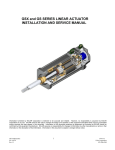
1
Installation Instructions
Logic Module, Internal CompactFlash, and RAM
Catalog Numbers 2711P-Rxxxx
Topic
Page
About the Components
1
Important User Information
2
Safety Precautions
3
About the Logic Module
3
Electrostatic discharge (ESD) wristband
5
Install or Replace RAM
7
Install or Replace the Internal CompactFlash
8
Marine Applications
11
Install a Logic Module
12
Replace a Logic Module
13
Additional Resources
14
About the Components
This document provides information on how to install these components:
• Logic module on a PanelView Plus or PanelView Plus CE device
• Memory (RAM and internal CompactFlash) in the logic module
For complete information on installing, wiring, and troubleshooting the terminals, refer to the
publications listed under Additional Resources.
This document refers to FactoryTalk View ME software that was previously named RSView
ME software.
2
Logic Module, Internal CompactFlash, and RAM
Important User Information
Solid state equipment has operational characteristics differing from those of electromechanical equipment.
Safety Guidelines for the Application, Installation and Maintenance of Solid State Controls (Publication
SGI-1.1 available from your local Rockwell Automation sales office or online at
http://literature.rockwellautomation.com) describes some important differences between solid state
equipment and hard-wired electromechanical devices. Because of this difference, and also because of the
wide variety of uses for solid state equipment, all persons responsible for applying this equipment must
satisfy themselves that each intended application of this equipment is acceptable.
In no event will Rockwell Automation, Inc. be responsible or liable for indirect or consequential damages
resulting from the use or application of this equipment.
The examples and diagrams in this manual are included solely for illustrative purposes. Because of the many
variables and requirements associated with any particular installation, Rockwell Automation, Inc. cannot
assume responsibility or liability for actual use based on the examples and diagrams.
No patent liability is assumed by Rockwell Automation, Inc. with respect to use of information, circuits,
equipment, or software described in this manual.
Reproduction of the contents of this manual, in whole or in part, without written permission of Rockwell
Automation, Inc., is prohibited.
Throughout this manual, when necessary, we use notes to make you aware of safety considerations.
WARNING
IMPORTANT
ATTENTION
Identifies information about practices or circumstances that can cause an explosion in
a hazardous environment, which may lead to personal injury or death, property
damage, or economic loss.
Identifies information that is critical for successful application and understanding of
the product.
Identifies information about practices or circumstances that can lead to personal injury
or death, property damage, or economic loss. Attentions help you identify a hazard,
avoid a hazard and recognize the consequences.
SHOCK HAZARD
Labels may be on or inside the equipment, for example, a drive or motor, to alert
people that dangerous voltage may be present.
BURN HAZARD
Labels may be on or inside the equipment, for example, a drive or motor, to alert
people that surfaces may reach dangerous temperatures.
Publication 2711P-IN004J-EN-P - September 2009
Logic Module, Internal CompactFlash, and RAM
3
Safety Precautions
Before installing or replacing components and modules, disconnect power from the terminal.
During the installation, be careful not to touch any of the exposed electronic components.
SHOCK HAZARD
ATTENTION
Disconnect all power from the terminal before installing or replacing any components.
Failure to disconnect power may result in electrical shock or damage to the terminal.
Be careful when touching any of the exposed electronic components to prevent damage
from electrostatic discharge (ESD). Work in a static free environment and wear a properly
grounded ESD wristband.
About the Logic Module
The logic module has these features:
•
•
•
•
Status indicators
Input power, DC or AC
Ethernet port, serial port, two USB ports, CompactFlash card slot
RAM and internal CompactFlash with firmware or operating system
Logic Module
Display Module
Logic modules are available as separate catalog numbers for field installation and are shipped
with or without memory installed. If RAM and internal CompactFlash are ordered separately,
you must install these components before attaching the logic module to the display module.
Publication 2711P-IN004J-EN-P - September 2009
4
Logic Module, Internal CompactFlash, and RAM
PanelView Plus and PanelView Plus CE Logic Modules
Cat. No.
Description
PanelView Plus or PanelView Plus CE 700 to 1500 Logic Modules (1)
2711P-RP
Logic module without flash/RAM memory, DC input
2711P-RPA
Logic module without flash/RAM memory, AC input(2)
2711P-RPD
Logic module without flash/RAM memory, isolated DC input(2)
PanelView Plus 700 to 1500 Logic Modules
2711P-RP1
Logic module with 64 MB flash/64 MB RAM, DC input
2711P-RP1A
Logic module with 64 MB flash/64 MB RAM, AC input(2)
2711P-RP1D
Logic module with 64 MB flash/64 MB RAM, isolated DC input(2)
2711P-RP2
Logic module with 128 MB flash/128 MB RAM, DC input
2711P-RP2A
Logic module with 128 MB flash/128 MB RAM, AC input(2)
2711P-RP2D
Logic module with 128 MB flash/ 128 MB RAM, isolated DC input(2)
2711P-RP2DK
Conformal-coated logic module with 128 MB flash/128 MB RAM, isolated DC input
2711P-RP2K
Conformal-coated logic module with 128 MB flash/128 MB RAM, DC input
2711P-RP3
Logic module with 256 MB flash/256 MB RAM, DC input
2711P-RP3A
Logic module with 256 MB flash/256 MB RAM, AC input(2)
2711P-RP3D
Logic module, 256 MB flash/256 RAM, isolated DC input(2)
PanelView Plus CE 700 to 1500 Logic Modules
2711P-RP6
PanelView Plus CE logic module with 128 MB flash/128 MB RAM, DC input
2711P-RP6A
PanelView Plus CE logic module with 128 MB flash/128 MB RAM, AC input(2)
2711P-RP6D
PanelView Plus CE logic module with 128 MB flash/128 MB RAM, isolated DC input(2)
2711P-RP6K
PanelView Plus CE conformal-coated logic module with 128 MB Flash/128 MB RAM, DC input
2711P-RP6DK
PanelView Plus CE conformal-coated logic module with 128 MB flash/128 MB RAM, isolated
DC input
2711P-RP7
PanelView Plus CE logic module with 256 MB flash/256 MB RAM, DC input
2711P-RP7A
PanelView Plus CE logic module with 256 MB flash/256 MB RAM, AC input(2)
2711P-RP7D
PanelView Plus CE logic module with 256 MB flash/256 MB RAM, isolated DC input(2)
(1)
These logic modules are compatible with any of the 2711P-RWx internal CompactFlash cards.
(2)
These logic modules are approved for marine applications.
Publication 2711P-IN004J-EN-P - September 2009
Logic Module, Internal CompactFlash, and RAM
5
Required Tools
The following tools are required for installation:
• #1 and #2 Phillips screwdriver
• Electrostatic discharge (ESD) wristband
Component Compatibility for PanelView Plus CE Terminals
It is important to match the series of the internal CompactFlash card with the correct series
of the logic module and software version. The series of the CompactFlash determines the
version of FactoryTalk View ME software and version of the operating system. The logic
module is available with or without memory installed.
Logic Module Compatibility
6189-RPx, 6189-RPRHx, 6189-RPEHx,
2711P-RPx, 2711P-RPx, 2711P-RP6x,
2711P-RP7x
Internal CompactFlash
6189-RW2, 6189-RW3,
6189-RW4, 2711P-RW6,
2711P-RW7, 2711P-RW8
FactoryTalk View ME and
OS Software Version
Series A: 6189-RPxH/A(1)
Series B: 6189-RWx/B
FactoryTalk View ME 3.0
Windows CE 3.0
Series B: 6189-RPxH/B
Series C: 6189-RWx/C
FactoryTalk View ME 3.10
Windows CE 4.1
Series B: 6189-RPxH/B
Series C: 6189-RPxH/C
Series D: 6189-RPxH/D
Series E: 6189-RPxHx/E
Series D: 6189-RWx/D
Series E: 6189-RWx/E
FactoryTalk View ME 3.20
Windows CE 4.1
FactoryTalk View ME 4.0
Windows CE 4.1
Series F: 2711P-RPxx/F(2)
Series F: 6189-RWx/F
Series G: 6189-RWx/G
Series H: 2711P-RWx/H
Series G: 2711P-RPxxx/G(2)
Series J: 2711P-RWx/J
FactoryTalk View ME 5.0 or 5.1
Windows CE 4.1
(1)
When upgrading from FactoryTalk View ME software, version 3.0 to 3.10 or later, the Firmware Upgrade Kit is
recommended.
(2)
Series F and later logic modules work with PanelView Plus and PanelView Plus CE CompactFlash cards.
Publication 2711P-IN004J-EN-P - September 2009
6
Logic Module, Internal CompactFlash, and RAM
Component Compatibility for PanelView Plus Terminals
It is important that you match the series of the internal CompactFlash card with the correct
series of the logic module and software version. The series of the CompactFlash determines
the version of FactoryTalk View ME software. The logic module is available with or without
memory installed.
Logic Module Compatibility
2711P-RPx, 2711P-RP1x,
2711P-RP2x, 2711P-RP3x
Internal CompactFlash
2711P-RW1, 2711P-RW2,
2711P-RW3
FactoryTalk View ME
Software Version
Series A: 2711P-RPx/A(1)
Series B: 2711P-RWx/B
FactoryTalk View ME 3.0
Series B: 2711P-RPx/B
Series C: 2711P-RWx/C
FactoryTalk View ME 3.10
Series B: 2711P-RPx/B
Series C: 2711P-RPx/C
Series D: 2711P-RPx/D
Series E: 2711P-RPxx/E
Series D: 2711P-RWx/D
Series E: 2711P-RWx/E
FactoryTalk View ME 3.20
FactoryTalk View ME 4.0
Series F: 2711P-RPxx/F(2)
Series F: 2711P-RWx/F
Series G: 2711P-RWx/G
Series H: 2711P-RWx/H
Series G: 2711P-RPxxx/G(2)
Series J: 2711P-RWx/J
FactoryTalk View ME 5.0 or 5.1
(1)
Series A logic modules are compatible with series B CompactFlash cards. When upgrading from FactoryTalk View ME
software, version 3.0 to 3.10 or later, the Firmware Upgrade Kit is required.
(2)
Series F and later logic modules work with PanelView Plus and PanelView Plus CE CompactFlash cards.
Compatibility After Upgrade
FactoryTalk View ME terminals are compatible with .MER applications that are the same or a
previous revision. For example, FactoryTalk View ME 3.20 terminals can run .MER
applications for FactoryTalk View ME software, versions 3.0, 3.10, and 3.20.
For PanelView Plus CE devices, the appropriate changes are made to the OS, from Windows
CE software, version 3.0 to 4.1, when upgrading from FactoryTalk View ME software,
version 3.0 to 3.10 or later.
Publication 2711P-IN004J-EN-P - September 2009
Logic Module, Internal CompactFlash, and RAM
7
Install or Replace RAM
The logic module is available with or without RAM installed. If ordered separately, you must
install the RAM before attaching the logic module to the display module.
RAM Memory Modules
Cat. No.
Description
2711P-RR64
64 MB SODIMM RAM for PanelView Plus and PanelView Plus CE terminals
2711P-RR128
128 MB SODIMM RAM for PanelView Plus and PanelView Plus CE terminals
2711P-RR128K
Conformal-coated 128 MB SODIMM RAM for PanelView Plus and PanelView
Plus CE terminals
2711P-RR256
256 MB SODIMM RAM for PanelView Plus and PanelView Plus CE terminals
Follow these steps to install or replace RAM.
1. Turn the logic module over to expose the circuit board.
2. Locate the RAM module on the circuit board.
3. Pull the metal retaining clips away from the module and slide out the RAM module.
4. Insert the new RAM module at a 45° angle and snap down.
Retaining Clip
Screw
CompactFlash Card
RAM
Module
Retaining Clips
Publication 2711P-IN004J-EN-P - September 2009
8
Logic Module, Internal CompactFlash, and RAM
Install or Replace the Internal CompactFlash
The logic module is available with or without CompactFlash installed. If ordered separately,
you must install the CompactFlash before attaching the logic module to the display module.
Internal CompactFlash
Cat. No.(1)
Description
2711P-RW1
64 MB internal CompactFlash with FactoryTalk View ME software for PanelView Plus
logic modules
2711P-RW2
128 MB internal CompactFlash with FactoryTalk View ME software for PanelView Plus
logic modules
2711P-RW3
256 MB internal CompactFlash with FactoryTalk View ME software for PanelView Plus
logic modules
2711P-RW6
128 MB internal CompactFlash with FactoryTalk View ME software for PanelView Plus CE
logic modules
2711P-RW7
256 MB internal CompactFlash with FactoryTalk View ME software for PanelView Plus CE logic
modules
2711P-RW8
512 MB internal CompactFlash with FactoryTalk View ME software for PanelView Plus CE logic
modules
(1)
The 2711P-RP, 2711P-RPD, and 2711P-RPA logic modules are compatible with any of the internal CompactFlash options.
Follow these steps to replace the internal CompactFlash.
1. Turn the logic module over to expose the circuit board.
2. Unscrew and remove the retaining clip that secures the internal CompactFlash card.
3. Pull out the internal CompactFlash card.
4. Insert the new internal CompactFlash card.
5. Reattach the retaining clip.
Publication 2711P-IN004J-EN-P - September 2009
Logic Module, Internal CompactFlash, and RAM
9
Battery Precautions
When you connect or disconnect the battery, an electrical arc can occur. This could cause
an explosion in hazardous location installations. Be sure that power is removed or the
area is nonhazardous before proceeding.
WARNING
For safety information on the handling of lithium batteries, including handling and
disposal of leaking batteries, see Guidelines for Handling Lithium Batteries, publication
AG 5-4. Replace the battery only with the indicated catalog number.
Do not dispose of battery in a fire or incinerator. Dispose of used batteries in accordance
with local regulations.
Store batteries in a cool, dry environment. We recommend 25 °C (77 °F) with 40…60%
relative humidity. You may store batteries for up to 30 days between -45…85 °C
(-49…185 °F), such as during transportation. To avoid possible leakage, do not store
batteries above 60 °C (140 °F) for more than 30 days.
Replace the Battery in PanelView Plus Terminals
Follow these steps to replace the battery in the logic module of PanelView Plus or PanelView
Plus CE terminals.
1. Disconnect power from the terminal.
2. Place the terminal, display side down, on a flat stable surface.
3. Detach the communication module, if attached, from the logic module by removing
the four screws.
4. Loosen the six captive screws that attach the logic module to the display module.
Communication Module
Screw
Logic Module
Captive
Screw
Display Module
5. Carefully lift the logic module away from the terminal and turn over to expose the
circuit board.
Publication 2711P-IN004J-EN-P - September 2009
10
Logic Module, Internal CompactFlash, and RAM
6. Locate the battery on the circuit board.
Lift up the edge of the
battery indicated by
the arrow.
7. Remove the battery by lifting up the side of the battery.
8. Insert the new battery.
9. Reattach the logic module by aligning the two connectors on the bottom of the
module with the connectors on the terminal.
10. Push down on the logic module until it is firmly seated.
11. Tighten the six captive screws that secure the logic module to a torque of 0.58 N•m
(5…7 lb•in).
12. Reattach the communication module, if necessary, and tighten the four screws to a
torque of 0.58 N•m (5…7 lb•in).
Publication 2711P-IN004J-EN-P - September 2009
Logic Module, Internal CompactFlash, and RAM
11
Ethernet Cable
Use Belden 7921A shielded Ethernet Category 5e cable according to TIA 568-B.1 and RJ45
connector according to IEC 60603-7 for compliance with Marine emissions limits and
European Union 89/336/EEC EMC Directive.
The maximum cable length between the terminal’s Ethernet port and a 10/100 Base-T port
on an Ethernet hub (without repeaters or fiber) is 100 m (328 ft). For additional information,
refer to the EtherNet/IP Media Planning and Installation Manual, publication ENET-IN001.
Marine Applications
Isolated DC logic modules require a line filter for use in marine applications. Use Corcom
6VW1 or equivalent filter type.
PanelView Plus
Marine Terminal
GND
DC- DC+
1 m (39 in.) max.
Earth/ground
GND to ground bus
Line
Filter
DCEarth/ground
GND to ground bus
DC+
Publication 2711P-IN004J-EN-P - September 2009
12
Logic Module, Internal CompactFlash, and RAM
Install a Logic Module
If the display module and logic module are ordered as separate components, attach the logic
module to the display module before panel installation.
1. Disconnect power from the terminal.
2. Set the display module of the terminal display-side down on a clean, flat, stable
surface to avoid scratches.
3. Position the logic module over the back of the display module until the two
connectors on the bottom of the logic module align with the connectors on the
display module.
Captive
Screw
4. Push down on the logic module until firmly seated.
5. Tighten the six captive screws that secure the logic module to the display module to a
torque of 0.58 N•m (5…7 lb•in).
Logic Module
Captive Screws
on Top and Bottom
Publication 2711P-IN004J-EN-P - September 2009
Logic Module, Internal CompactFlash, and RAM
13
Replace a Logic Module
Before replacing the logic module, you must remove the communication module, if attached.
Remove the internal CompactFlash card and RAM from the logic module if you want to
reuse the memory in the new logic module.
Follow these steps to replace the logic module.
1. Disconnect power from the terminal.
2. Disconnect all power and communication cables.
WARNING
Do not connect or disconnect any communication cable with power applied to this device
or any device on the network. An electrical arc could cause an explosion in hazardous
location installations. Be sure that power is removed or the area is nonhazardous before
proceeding.
3. Set the terminal display-side down on a clean, flat, stable surface to prevent scratches
if the terminal is removed from a panel.
4. Remove the four screws that secure the communication module, if attached, to the
logic module and carefully lift the communication module away from the logic
module.
Communication Module
Screw
Logic Module
Screw
Display Module
5. Loosen the six captive screws that secure the logic module.
6. Carefully lift the logic module away from the back of the display module.
Publication 2711P-IN004J-EN-P - September 2009
14
Logic Module, Internal CompactFlash, and RAM
7. If reusing the memory in the new logic module:
• remove the RAM and CompactFlash from the logic module.
• insert the RAM and CompactFlash in the new logic module.
To verify component compatibility, refer to the tables on page 5 and 6.
8. Install the new or used logic module.
9. Install the communication module, if necessary.
Additional Resources
For additional information on the PanelView Plus and PanelView Plus CE terminals, refer to
these publications.
Resource
Description
PanelView Plus User Manual, publication
2711P-UM001
Provides an overview of the PanelView Plus and PanelView
Plus CE terminals and gives information on how to install,
operate, configure, and troubleshoot these devices.
PanelView Plus Terminals and Display
Modules Installation Instructions, publication
2711P-IN001
Provides specific guidelines and procedures on how to install
PanelView Plus, PanelView Plus CE terminals, and display
modules in a panel.
High-bright Display Modules Installation
Instructions, publication 2711P-IN026
Provides specific guidelines and procedures on how to install
a high-bright display module to a PanelView Plus or
PanelView Plus CE terminal in outdoor environments.
Wiring and Grounding Guidelines for
PanelView Plus Devices Technical Data,
publication 2711P-TD001
Provides additional grounding and wiring guidelines for
PanelView Plus and PanelView Plus CE terminals.
You can view or download publications at http://literature.rockwellautomation.com. To
order paper copies of technical documentation, contact your local Rockwell Automation
distributor or sales representative.
Publication 2711P-IN004J-EN-P - September 2009
Logic Module, Internal CompactFlash, and RAM
15
Notes:
Publication 2711P-IN004J-EN-P - September 2009
Rockwell Automation Support
Rockwell Automation provides technical information on the Web to assist you in using its
products. At http://support.rockwellautomation.com, you can find technical manuals, a
knowledge base of FAQs, technical and application notes, sample code and links to software
service packs, and a MySupport feature that you can customize to make the best use of these
tools.
For an additional level of technical phone support for installation, configuration and
troubleshooting, we offer TechConnect support programs. For more information, contact
your local distributor or Rockwell Automation representative, or visit
http://support.rockwellautomation.com.
Installation Assistance
If you experience a problem within the first 24 hours of installation, please review the
information that's contained in this manual. You can also contact a special Customer Support
number for initial help in getting your product up and running.
United States
1.440.646.3434
Monday – Friday, 8 a.m. – 5 p.m. EST
Outside United
States
Please contact your local Rockwell Automation representative for any
technical support issues.
New Product Satisfaction Return
Rockwell Automation tests all of its products to ensure that they are fully operational when
shipped from the manufacturing facility. However, if your product is not functioning and
needs to be returned, follow these procedures.
United States
Contact your distributor. You must provide a Customer Support case number
(see phone number above to obtain one) to your distributor in order to
complete the return process.
Outside United
States
Please contact your local Rockwell Automation representative for the return
procedure.
PanelView Plus, PanelView Plus CE, RSView ME, FactoryTalk View, Allen-Bradley, Rockwell Automation, and TechConnect are trademarks
of Rockwell Automation, Inc.
Trademarks not belonging to Rockwell Automation are property of their respective companies.
Publication 2711P-IN004J-EN-P - September 2009
Supersedes Publication 2711P-IN004I-EN-P - September 2008
PN-54637
Copyright © 2009 Rockwell Automation, Inc. All rights . Printed in the U.S.A.