1
Installation
Manual
PT-602CZ Camera
.
© 2012 FLIR Commercial Systems, Inc. All rights reserved worldwide. No parts of this manual, in whole or in part,
may be copied, photocopied, translated, or transmitted to any electronic medium or machine readable form without
the prior written permission of FLIR Commercial Systems, Inc.
Names and marks appearing on the products herein are either registered trademarks or trademarks of FLIR
Commercial Systems, Inc. and/or its subsidiaries. All other trademarks, trade names, or company names
referenced herein are used for identification only and are the property of their respective owners.
This product is protected by patents, design patents, patents pending, or design patents pending.
If you have questions that are not covered in this document, or need service, contact FLIR customer support.
http://support.flir.com/
Phone - US: 888.747.FLIR (888.747.3547)
International: +1.805.964.9797
The contents of this document are subject to change.
Proper Disposal of Electrical and Electronic Equipment (EEE)
The European Union (EU) has enacted Waste Electrical and Electronic Equipment Directive 2002/96/EC
(WEEE), which aims to prevent EEE waste from arising; to encourage reuse, recycling, and recovery of EEE
waste; and to promote environmental responsibility.
In accordance with these regulations, all EEE products labeled with the “crossed out wheeled bin” either on the
product itself or in the product literature must not be disposed of in regular rubbish bins, mixed with regular
household or other commercial waste, or by other regular municipal waste collection means. Instead, and in
order to prevent possible harm to the environment or human health, all EEE products (including any cables that
came with the product) should be responsibly discarded or recycled.
To identify a responsible disposal method where you live, please contact your local waste collection or recycling service, your
original place of purchase or product supplier, or the responsible government authority in your area. Business users should
contact their supplier or refer to their purchase contract.
Important Instructions and Notices to the User:
Modification of this device without the express authorization of FLIR Commercial Systems, Inc. may void the user’s
authority under FCC rules to operate this device.
Note 1: This equipment has been tested and found to comply with the limits for a Class B digital device, pursuant to
Part 15 of the FCC rules. These limits are designed to provide reasonable protection against harmful interference in
a residential installation. This equipment generates, uses, and can radiate radio frequency energy and, if not
installed and used in accordance with the instructions, may cause harmful interference to radio communications.
However, there is no guarantee that the interference will not occur in a particular installation. If this equipment does
cause harmful interference to radio or television reception, which can be determined by turning the equipment off
and on, the user is encouraged to try to correct the interference by one or more of the following measures:
• Reorient or relocate the receiving antenna;
• Increase the separation between the equipment and receiver;
• Connect the equipment into an outlet on a circuit different from that of the receiver; and/or
• Consult the dealer or an experienced radio/television technician for help.
Note 2: This equipment was tested for compliance with the FCC limits for a Class B digital device using a shielded
cable for connecting the equipment to an analog video output to a monitor and using a shielded USB cable for
connecting the equipment to a personal computer. When making such connections, shielded cables must be used
with this equipment.
Industry Canada Notice:
This Class B digital apparatus complies with Canadian ICES-003.
Avis d’Industrie Canada:
Cet appareil numérique de la classe B est conforme à la norme NMB-003 du Canada.
PT-602CZ-12, Rev. 100—PT-602CZ Installation Manual, April 2012
ii
Table of Contents
1 PT-602CZ Camera Installation
1.1 Warnings and Cautions .............................................................................................. 1-1
1.2 References ................................................................................................................. 1-1
1.3 Installation Overview ................................................................................................... 1-2
1.4 Installation Components ............................................................................................. 1-3
1.5 Location Considerations ............................................................................................. 1-3
1.6 Prior to Cutting/Drilling Holes ...................................................................................... 1-4
1.7 Camera Mounting ....................................................................................................... 1-4
1.8 Removing the Back Cover .......................................................................................... 1-5
1.8.1 Cable Gland Sealing .......................................................................................... 1-5
1.8.2 Cable Glands and Spare Parts Kit ..................................................................... 1-5
1.8.3 Cable Gland Seal Inserts ................................................................................... 1-6
1.9 Electrical Connections ................................................................................................ 1-7
1.10 Connecting power .................................................................................................... 1-8
1.11 Video Connections ................................................................................................... 1-8
1.12 Ethernet Connection ................................................................................................. 1-9
1.13 Serial Communications Overview ............................................................................. 1-9
1.14 Serial Connections ................................................................................................... 1-9
1.15 Setting Configuration Dip Switches ........................................................................ 1-10
1.16 PT-602CZ Camera Specifications .......................................................................... 1-12
2 Verify Camera Operation
2.1 Power and analog video ............................................................................................. 2-1
2.2 Initial Power Up ........................................................................................................... 2-1
2.2.1 Cool Down Period .............................................................................................. 2-1
2.3 Verify Serial Communications ..................................................................................... 2-2
2.4 Verify IP Communications .......................................................................................... 2-2
2.5 Using FLIR Sensors Manager (FSM) .......................................................................... 2-3
2.5.1 Running FSM ..................................................................................................... 2-3
2.5.2 Non- Uniformity Correction (NUC) ..................................................................... 2-5
2.6 Troubleshooting Tips .................................................................................................. 2-8
2.6.1 Camera not discovered ..................................................................................... 2-8
2.6.2 Unable to control the camera ............................................................................. 2-9
2.6.3 General Errors ................................................................................................. 2-10
2.6.4 Image Artifacts (Ghosting) in the Video ........................................................... 2-10
2.6.5 Unable to View Video Stream .......................................................................... 2-10
2.7 Restoring the Factory Network Settings ................................................................... 2-12
3 PT-602CZ Configuration
3.1 LAN Settings ............................................................................................................. 3-2
3.2 Date and Time ............................................................................................................ 3-3
3.3 Serial Remote Menu ................................................................................................... 3-4
3.4 Configuration File ....................................................................................................... 3-5
3.5 Mechanical ICD Reference ......................................................................................... 3-6
4 Serial Addresses: Decimal To Binary Conversion
PT-602CZ-12, version 100
April 2012
-iii
Table of Contents
iv
PT-602CZ Installation Manual
PT-602CZ-12, version 100
1
PT-602CZ Camera Installation
1
PT-602CZ Camera Installation
The PT-602CZ is a pan/tilt thermal security camera for medium- to long-range applications and can be
used with traditional analog video installations or IP video networks. It incorporates a high-sensitivity
thermal camera and a long-range daylight camera with a precision pan/tilt platform.
The PT-602CZ camera includes a cooled, high-performance thermal imager which is optimized for
medium- to long-range surveillance.The thermal imager brings together a sensitive third generation midwave FPA detector with 640x512 pixels, powerful video-processing electronics, and continuous zoom
optics incorporated into a compact package.
This manual describes the installation of the PT-602CZ cameras. If you have questions that are not
covered in this document, or need service, contact FLIR customer support.
http://support.flir.com/
Phone - US: 888.747.FLIR (888.747.3547)
International: +1.805.964.9797.
This manual includes the following topics:
•
•
•
•
Installation Overview
Mounting the camera and its components
Connecting the electronics
Basic configuration and operation
For safety, and to achieve the highest levels of performance from the camera system, always follow the
warnings and cautions in this manual when handling and operating the PT-602CZ.
1.1
Warnings and Cautions
WARNING!
If mounting the PT-602CZ camera on a pole, tower or any elevated location, use industry standard
safe practices to avoid injuries.
Caution!
Except as described in this manual, do not open the PT-602CZ camera for any reason. Disassembly
of the camera (including removal of the cover) can cause permanent damage and will void the
warranty.
Be careful not to leave fingerprints on the PT-602CZ camera’s infrared optics.
The PT-602CZ camera requires a power supply of 24 Volts. Operating the camera outside of the
specified input voltage range or the specified operating temperature range can cause permanent
damage.
When lifting the PT-602CZ camera use the camera body and base, not the tubes.
1.2
•
References
Nexus IP Camera Configuration Guide (FLIR document # 427-0030-00-28)
PT-602CZ-12, version 100
April 2012
1-1
1
PT-602CZ Camera Installation
•
1.3
PT-602CZ Mechanical Interface Control Document (ICD) available on the documentation CD or
from the FLIR website (FLIR document # T1002.M100- ICD PT 602 CZ)
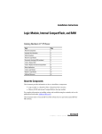
Installation Overview
The PT-602CZ Camera is a multi-sensor camera system on a pan/tilt platform. Combinations of an
infrared thermal imaging camera and a visible-light video camera are intended for outdoor
installations.
Shipping plugs only Remove before installing
Figure 1-1: PT-602CZ Camera
The PT-602CZ camera is intended to be mounted on a medium-duty fixed pedestal mount or wall
mount commonly used in the CCTV industry. Cables will exit from the back of the camera housing.
The mount must support up to 45 LBS. (20 KG).
The PT-602CZ camera is both an analog and an IP camera. The video from the camera can be
viewed over a traditional analog video network or it can be viewed by streaming it over an IP network
using MPEG-4, M-JPEG and H.264 encoding. Analog video will require a connection to a video monitor or an analog matrix/switch. The IP video will require a connection to an Ethernet network switch,
and a computer with the appropriate software for viewing the video stream.
The camera can be controlled through either serial or IP communications.
The camera operates on 20 - 30 VAC or 21 - 30 VDC.
Important Note
Install all cameras with an easily accessible Ethernet connection to support future software upgrades.
In order to access the electrical connections and install the cables, it is necessary to temporarily
remove the back cover of the camera housing.
Important Note
To account for pixel variations across the detector array (640x512 = 327,680 pixels), it is
recommended a NUC operation is executed each time the camera is powered up, and periodically or
as needed after that to improve the quality of the image. Refer to section 2.5.2 “Non- Uniformity
Correction (NUC)” on page 2-5.
1-2
PT-602CZ-12 Rev 100
April 2012
1
PT-602CZ Camera Installation
1.4
Installation Components
The PT-602CZ camera includes these standard components:
•
•
•
•
Multi-sensor Pan/Tilt Camera Unit
Cable Glands and Spare Parts kit
FLIR Sensors Manager CD
PT-602CZ Camera Documentation Package (including Documentation CD)
The installer will need to supply the following items; the lengths are specific to the installation.
•
Electrical wire, for system power. Refer to section 1.9 “Electrical Connections” on page 1-7 for
additional information)
Camera grounding strap
Coaxial RG59U video cables (BNC connector at the camera end) for analog video
Shielded Category 6 Ethernet cable for control and streaming video over an IP network; and also
for software upgrades.
Optional serial cable for serial communications.
Miscellaneous electrical hardware, connectors, and tools
•
•
•
•
•
1.5
Location Considerations
The camera will require connections for power, communications (IP Ethernet, and/or RS232/RS422},
and video (two video connections may be required for analog video installations). The PT-602CZ
camera must be mounted upright on top of the mounting surface, with the base below the camera.
The unit should not be hung upside down.
Not to scale
Maximum exclusion cylinder
Ø25.5” x 17.4” high
Ø650mm x 445mm high
Figure 1-2: PT-602CZ Pan and Tilt Exclusion Zone
PT-602CZ-12 Rev100
April 2012
1-3
PT-602CZ Camera Installation
1.6
Prior to Cutting/Drilling Holes
When selecting a mounting location for the PT-602CZ camera, consider cable lengths and cable
routing. Ensure the cables are long enough given the proposed mounting locations and cable routing
requirements. Use cables that have sufficient dimensions to ensure safety (for power cables) and
adequate signal strength (for video and communications).
Ensure that cable distances do not exceed the Referenced Standard specifications and adhere to all
local and Industry Standards, Codes, and Best Practices.
1.7
Camera Mounting
Caution!
When lifting the PT-602CZ camera use the camera body and base, not the tubes.
Not to scale
Dimensions in inches (and millimeters)
0
2X 2.72 ± .02
(2X 69 ± .5)
The PT-602CZ camera can be secured to the mount with four 5/16 or M8 bolts, as shown below.
2X 2.72 ± .02
(2X 69 ± .5)
1
4X Ø.354 (9.0) THRU
2X 3.19 ± .02
(2X 80.5 ± .5)
0
Tilt Axis
0.28
(7.5)
2X 3.19 ± .02
(2X 80.5 ± .5)
Pan Axis
Figure 1-3: PT-602CZ Camera Mounting
Once the mounting location has been selected, verify both sides of the mounting surface are
accessible.
Important Note
Connect and operate the camera as a bench test at ground level prior to mounting the camera in its
final location.
1-4
PT-602CZ-12 Rev 100
April 2012
1
PT-602CZ Camera Installation
Once the holes are drilled in the mounting surface, install four (4) 5/16 or M8 bolts through the base of
the camera. Use a thread locking compound such as Loctite 242 or equivalent with all metal to metal
threaded connections.
1.8
Removing the Back Cover
Use a cross-tip screwdriver to loosen
the six captive screws and remove the
cover, exposing the connections at the
back of the camera. There is a
grounding wire connected between the
case and the back cover; if the wire is
temporarily disconnected during
installation, reconnect the wire to
ensure proper grounding.
1.8.1
Cable Gland Sealing
Proper installation of cable sealing
glands and use of appropriate
elastomer inserts is critical to long term
reliability. Cables enter the camera
mount enclosure through liquid-tight
compression glands. Be sure to insert the cables through the cable glands on the enclosure before
terminating and connecting them (the connectors will not fit through the cable gland). Leave the gland
nuts loosened until all cable installation has been completed. Inspect and install gland fittings in the
back cover with suitable leak sealant and tighten to ensure water tight fittings. Teflon tape or pipe
sealant (i.e. DuPont RectorSeal T™) are suitable for this purpose.
1.8.2
Cable Glands and Spare Parts Kit
The kit contains the two 3/4” cable glands and gland
seal plugs required for non-conduit installations.
The remaining parts included in the kit are:
•
•
•
•
•
•
a spare ground wire
a spare ground nut and lock washer
two spare power terminal block plugs
two spare serial port terminal block plugs
four spare F-Series back cover screws
four spare PT-Series back cover screws
PT-602CZ-12 Rev100
April 2012
1-5
1
PT-602CZ Camera Installation
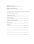
1.8.3
Cable Gland Seal Inserts
The PT-602CZ camera comes with two 3/4”
NPT cable glands, each with a three hole
gland seal insert. Cables may be between
0.23" to 0.29" (0.59cm to 0.73cm) od. Up to
six cables may be installed. Plugs are
required for the insert hole(s) not being used.
The photograph at the right shows two power
cables, an Ethernet cable, a serial control
cable (no analog video is installed), and two
gland seal plugs.
gland seal plugs
Ground
Lug
Ethernet
Camera
Power
If non-standard cable diameters are used, you
may need to locate or fabricate the
appropriate insert to fit the desired cable.
FLIR Commercial Systems, Inc. does not
Serial Control
provide cable gland inserts other than what is
supplied with the system.
Heater
Power
Note
Insert the cables through the cable glands on the enclosure before terminating and connecting them.
In general, the terminated connectors will not fit through the cable gland. If a terminated cable is
required, you can make a clean, singular cut in the gland seal to install the cable into the gland seal.
1-6
PT-602CZ-12 Rev 100
April 2012
PT-602CZ Camera Installation
1.9
Electrical Connections
Serial and IP Communications
Main Analog Video
Auxiliary Analog Video and Power
Male
BNC
Ethernet
Male
BNC
3
2
1
{
{
24 VAC/DCEarth Ground
24 VAC/DC+
3/4” NPT for Cable
Gland or Conduit
{
RS422
TX+
GND
RX+
RS232
Auxiliary
Port
3
2
1
Main
Port
24 VAC/DCEarth Ground
24 VAC/DC+
5 4 3 2 1
TD(B)+
TD(A)GND
RD(B)+
RD(A)-
1
20 AWG MAX
Chassis
GND
16 AWG Shielded
Back Cover
16 AWG Shielded
Serial
Control
Ethernet
Video
24
VAC/DC
24
VAC/DC
Gland B Camera End
Gland A Camera End
PT-602CZ-12 Rev100
Video
Local
GND
April 2012
1-7
1
PT-602CZ Camera Installation
IP Network
Analog Video
(monitoring output only)
Analog Visible Video
Not used
Serial Connector
for local control
Camera Power
Heater Power
Analog Infrared Video
Figure 1-4: PT-602CZ Camera Connections
1.10
Connecting power
The camera itself does not have an on/off switch. Generally the PT-602CZ camera will be connected
to a circuit breaker and the circuit breaker will be used to apply or remove power to the camera. If
power is supplied to it, the camera will be in one of two modes: Booting Up or Powered On.
The power cable supplied by the installer must use wires that are sufficient size gauge (16 AWG
recommended) for the supply voltage and length of the cable run, to ensure adequate current
carrying capacity. Always follow local building codes!
Ensure the camera is properly grounded. Typical to good grounding practices, the camera chassis
ground should be provided using the lowest resistance path possible. FLIR requires using a
grounding strap anchored to the grounding lug on the back plate of the camera housing and
connected to the nearest earth-grounding point.
Note
The terminal blocks for power connections will accept a maximum 16 AWG wire size.
1.11
Video Connections
The analog video connections on the back of the camera are BNC connectors. A video monitoring
connection (RCA jack) is intended for temporary use and allows the video to be monitored without
disconnecting the BNC connections.
The video cable used should be rated as RG59U or better to ensure a quality video signal.
1-8
PT-602CZ-12 Rev 100
April 2012
1
PT-602CZ Camera Installation
1.12
Ethernet Connection
The camera provides a standard RJ 45 Ethernet jack. The cable gland seal is designed for use with
Shielded Category 6 Ethernet cable.
1.13
Serial Communications Overview
The installer must first decide if the serial communications settings will be configured via hardware
(DIP switch settings) or software. If the camera has an Ethernet connection, then generally it will be
easier (and more convenient in the long run) to make configuration settings via software. Then
configuration changes can be made over the network without physically accessing the camera. Also
the settings can be saved to a file and backed up or restored as needed.
If the camera is configured via hardware, then configuration changes in the future may require
accessing the camera on a tower or pole, dismounting it, and removing the back and so on. If the
camera does not have an Ethernet connection, the DIP switches must be used to set the serial
communication options.
Important Note
The serial communications parameters for the PT-602CZ camera are set or modified either via
hardware DIP switch settings or via software, through a web browser interface. A single DIP switch
(SW102-9, Software Override determines whether the configuration comes from the hardware DIP
switches or the software settings.
Note
The DIP switches are only used to control serial communications parameters. Other settings, related
to IP camera functions and so on, must be modified via software (using a web browser).
1.14
Serial Connections
For serial communications, it is necessary to set the parameters such as the signalling standard (RS232 or RS-422), baud rate, number of stop bits, parity and so on. It is also necessary to select the
communication protocol used (either Pelco D or Bosch) and the camera address.
Note
Typical Bosch systems operate using a biphase connection and the FLIR cameras do not accept
biphase signals directly. It may be necessary to install a biphase converter in order to use the Bosch
protocol.
The camera supports RS-422 and RS-232 serial communications using common protocols. When
using the RS-422 standard, ensure the transmit pair of the camera goes to the receive pair of the
other device, and vice versa.
Note
The terminal blocks for serial connections will accept a maximum 20 AWG wire size.
PT-602CZ-12 Rev100
April 2012
1-9
1
PT-602CZ Camera Installation
1.15
Setting Configuration Dip Switches
The figure below shows the locations of dip switches SW102 and SW103.
SW103
SW102
Switch
Position
Off
On
Figure 1-5: PT-602CZ Camera Configuration
Address: This is the address of the system when configured for serial communications. The available
range of values is from decimal 1 to 255. The dip switches are interpreted as a binary number, with
switch 1 representing the least significant bit (the switches are in the reverse order of the bits). For
convenience, a table of serial addresses and their binary equivalents is included at the end of the
manual. See “Serial Addresses: Decimal To Binary Conversion” on page 4-1.
Table 1-1: Dip Switch Address/ID Settings—SW102
Address
Sw1
Sw 2
Sw 3
1
ON
OFF
OFF
2
OFF
ON
3
ON
…
255
Sw4
Sw 5
Sw 6
Sw 7
Sw 8
OFF
OFF
OFF
OFF
OFF
OFF
OFF
OFF
OFF
OFF
OFF
ON
OFF
OFF
OFF
OFF
OFF
OFF
…
…
…
…
…
…
…
…
ON
ON
ON
ON
ON
ON
ON
ON
Other Serial Communication Parameters. The tables below defines the switch locations, bit
numbering and on/off settings.
Table 1-2: Dip Switch Settings—SW103
Settings
Baud rate: This is the baud rate of the system user serial
port. The available values are 2400, 4800, 9600, 19200
kbaud.
1-10
PT-602CZ-12 Rev 100
Description
Bit 1
Bit 2
OFF
OFF
2400
ON
OFF
4800
OFF
ON
9600
ON
ON
19200
April 2012
1
PT-602CZ Camera Installation
Table 1-2: Dip Switch Settings—SW103
Settings
Camera Control Protocol: This is the communication
protocol selected for the system when operating over the
serial port. The available protocols are Pelco-D and Bosch
(see Note below regarding Bosch systems).
Serial Communication Standard: This determines the
electrical interface selected for the user serial port. The
available settings are RS422 and RS232.
Not Used
Software Override DIP Switch: This setting determines
whether the system will use software settings for
configuration or if the dip switch settings will override the
software settings. Default is Off.
Description
Bit 3
Bit 4
OFF
OFF
Pelco-D
ON
OFF
NA
OFF
ON
Bosch
ON
ON
NA
Bit 5
Bit 6
OFF
OFF
NA
ON
OFF
RS422
OFF
ON
RS232
ON
ON
N/A
Bit 7
Bit 8
X
X
X
X
X
X
X
X
Bit 9
OFF
Software select
ON
Hardware select
Bit 10
Not Used
X
Note
Typical Bosch systems operate using a biphase connection and the FLIR cameras do not accept
biphase signals directly. It may be necessary to install a biphase converter in order to use the Bosch
protocol.
PT-602CZ-12 Rev100
April 2012
1-11
1
PT-602CZ Camera Installation
1.16
PT-602CZ Camera Specifications
Thermal Camera Specifications
Array Format
640 × 480 (NTSC), 640 x 512 (PAL)
Detector Type
Cooled Mercury Cadmium Telluride (MCT)
Spectral Range
3.7 to 4.8 μm
Thermal Sensitivity
<30 mK @ 25 °C
Effective Resolution
307,200 (NTSC), 327,680 (PAL)
Field Of View
WFOV: 28° x 22.4° (PAL) 28° x 21° (NTSC)
NFOV: 2° x 1.6° (PAL)
2° x 1.5° (NTSC)
Focus
Auto focus or manual focus
Optical zoom
Continuous
Image frequency
25 Hz / 30 Hz video standard PAL/NTSC
Visible Camera Specifications
Detector Type
1/4” Exview HAD CCD
Effective resolution
380,000 (NTSC), 444,000 (PAL)
Field Of View
Field of view: 57.8° (H) to 1.7° (H)
Lens
3.4mm (wide) to 122.4 mm (narrow), F1.6 to F4.5
Outputs
Composite Video
NTSC or PAL Standard
Video Streaming
MPEG-4, H.264, or M-JPEG
Control
Ethernet
FLIR Sensors Manager Standard
Serial
RS-232/-422 (Pelco D, Bosch)
External Analytics Compatible
yes
Pan/Tilt
Pan Angle/Speed
Continuous 360°; 0.1° to 60°/sec
Tilt Angle/Speed
+90° to -90°; 0.1° to 30°/sec
Programmable presets
128
General
Weight
~40 lb (18.5kg)
Dimensions (L,W,H)
13.8” × 19” × 13.1” (352 mm x 495 mm x 333 mm)
Power
Input Voltage
24 VAC (21-30 VAC) ; 24 VDC (21-30 VDC)
Power Consumption
24 VAC: 70 VA max w/o heaters; 260 VA w/heaters
24VDC: 60 W max w/o heaters; 230W w/heaters
Note
Power consumption is independent of the input voltage when the heater is off. The power drawn by
the heaters increases with the input voltage to a maximum at 30 Volts.
1-12
PT-602CZ-12 Rev 100
April 2012
2
Verify Camera Operation
2
Verify Camera Operation
Prior to installing the camera, use a bench test to verify camera operation and configure the camera for
the local network. The camera provides analog video and can be controlled through either serial or IP
communications providing streaming video over an IP network.
2.1
Power and analog video
Step 1
Connect the power, video, and serial cables to the camera as described in section 1.9
“Electrical Connections” on page 1-7.
Step 2
Connect the video cable from the camera to a display/monitor and connect the power cable to
a power supply.
The camera operates on 21 - 30 VAC or 21 - 30 VDC.
Verify that video is displayed on the monitor.
Step 3
If serial communications will be used, connect the serial cable from the camera to a serial
device such as a keyboard, and confirm that the camera is responding to serial commands.
Before using serial communications, it may be necessary to configure the camera to operate
with the serial device.
2.2
Initial Power Up
After the connections have been made, apply power to the camera. After the camera is turned and the
server has booted up (approximately 90 seconds), the video temporarily displays system information
including the serial number, IP address, Pelco address, Baud rate, and setting of the serial control DIP
switch: SW - software control (the default) or HW - hardware.For example:
S/N: 1234567
IP Addr: 192.168.250.116
PelcoD (Addr:1): 2400 SW
Just after the power is turned on, the zoom lens will execute a Built In Test (BIT). Then it will be
automatically set to the wide field of view (28°).
2.2.1
Cool Down Period
The thermal imager is cooled by a compact integral Stirling cooler
(also known as a cryocooler) which starts automatically when the
camera is powered on. The cryocooler makes an audible noise
when it is operating, and it requires up to 8 minutes to cool the
detector down to its operating temperature. When it is cooling down,
the video image shows a fixed test pattern, rather than live video.
PT-602CZ-12, version 100
April 2012
2-1
2
Verify Camera Operation
2.3
Verify Serial Communications
If using serial communications with the camera, use the serial control device (such as a keyboard) to
move the camera pan/tilt and zoom in/out. By default, commands from a serial device have higher
priority than commands from an IP client such as FLIR Sensors manager.
The camera supports the following Pelco D Aux commands.
Pelco command
Aux 1 ON
Aux 1 OFF
Aux 2 ON
Aux 2 OFF
Aux 3 OFF
Aux 4 ON
Aux 4 OFF
Aux 5 OFF
Aux 9 OFF
2.4
Command
FF 01 00 09 00 01 0B
FF 01 00 0B 00 01 0D
FF 01 00 09 00 02 0C
FF 01 00 0B 00 02 0E
FF 01 00 0B 00 03 0F
FF 01 00 09 00 04 0E
FF 01 00 0B 00 04 10
FF 01 00 0B 00 05 11
FF 01 00 0B 00 09 15
PT series
IR polarity Black Hot IR polarity White Hot
DLTV change active source
IR change active source
Toggle AGC type (manual/auto)
Toggle Autofocus
IR start NUC calibration (blurred NUC)
Toggle IR polarity White Hot/Black Hot
Go to Park Position
Verify IP Communications
As shipped from the factory, the PT-602CZ camera has an IP address of 192.168.250.116 with a
netmask of 255.255.255.0.
Step 1
Configure a laptop or PC with another IP address from this network (for example,
192.168.250.1).
Step 2
Connect the camera and the laptop to the same Ethernet switch (or back-to-back with an
Ethernet crossover cable).1
Step 3
Open a web browser, enter http://192.168.250.116 in
the address bar, and press Enter.
The Web Configuration Tool will start at the Login
screen. If the Login screen appears, then you have
established IP communications with the camera. It is
not necessary to log in and use the Web Configuration
Tool right away. At this time, perform a bench test of
the camera using the FLIR Sensors Manager software
and the factory configured IP address. Refer to
section 2.5 “Using FLIR Sensors Manager (FSM)” on
page 2-3 for more information.
1. In some cases, a straight Ethernet cable can be used, because many PCs have
auto detect Ethernet interfaces.
2-2
PT-602CZ-12 Rev 100
April 2012
2
Verify Camera Operation
2.5
Using FLIR Sensors Manager (FSM)
The following provides a brief description of how to use FSM to control a camera and stream video
from the camera. For more detailed information on how to use FSM, refer to the FLIR Sensors
Manager User Manual.If the FSM software has not been installed yet, locate the CD that came with
the camera (or download it from http://support.flir.com/) and install it on the PC.
2.5.1
Running FSM
Step 1
Run the FSM software by double clicking the icon on the desktop, or click on
the Windows Start button and select Programs > FLIR Sensors Manager
2012 > FLIR Sensors Manager.
Initially the FLIR Sensors Manager splash screen will be displayed. The software version
may be different than the version displayed below.
After a brief while, the FSM main window will appear, and a popup FSM Notification
window will appear in the lower right of the screen indicating that no cameras (servers)
have been discovered yet.
PT-602CZ-12 Rev100
April 2012
2-3
2
Verify Camera Operation
Step 2
Click on the Accept button to acknowledge the notification.
The FLIR Sensors Manager uses a “client/server” architecture. The FSM software is
considered a client, and the cameras are considered servers or sensors.
The Sensors Panel in the upper left of the window indicates no sensors have been
discovered and added to the list of Active Sensors.
Step 3
Click on Setup, then the Discovery button on the side panel to bring up the Discovery
Panel. The FSM software can automatically discover FLIR cameras on the network.
Step 4
When the Discovery Panel is displayed, click Refresh.
The FLIR camera will appear in the list of Discovered Servers. The camera will appear as
“(*)FLIR”, and the asterisk in parenthesis “(*)” indicates the camera has not been added to
the list of Active Servers on the right.
Step 5
Click on the center bar “>” to move the camera over to the list of Active Servers.
By default, the FSM software will automatically discover sensors in the network, connect to
the first camera it finds, take control of the camera, and display the video from the camera
in Video Wall 0.
No Sensors Discovered
Zoom/Pan/Tilt
Camera Controls
2-4
3. Refresh
1. Setup
2. Discovery
4. Move to Active
PT-602CZ-12 Rev 100
April 2012
2
Verify Camera Operation
Step 6
Confirm that video is streamed to the monitor and it is possible to control the camera using
the zoom controls and so on. For example, click on the zoom button (magnifying glass with
+), and the video will zoom in. Once operation of the camera has been confirmed, the
camera can be configured to an IP address that matches the installation network.
Step 7
Return to the Web Configuration Tool screen
shown at the right and select Login as Basic
User or enter basic as the User and click
Login.
No password is required.
The Web Configuration Tool will display the
Help screen listing information on the
camera’s software and hardware
configuration. The menu on the left allows
you to select various configuration web
pages in order to set the camera parameters.
Refer to section “Refer to the Nexus IP
Camera Configuration Guide (FLIR
document # 427-0030-00-28) for more information about camera configuration.” on page 25 for basic information about how to configure the camera for your network and application.
Refer to the Nexus IP Camera Configuration Guide (FLIR document # 427-0030-00-28) for
more information about camera configuration.
2.5.2
Non- Uniformity Correction (NUC)
To account for pixel variations across the detector array (640x512 = 327,680 pixels), it is
recommended a NUC operation is executed each time the camera is powered up, and periodically or
as needed after that to improve the quality of the image. If there is a change in ambient temperature or
if the camera integration time is adjusted, it may be necessary to perform a NUC operation.
A NUC operation is in some ways like a brief calibration step. With a one-point external NUC, the
objective is to point the camera toward a fairly uniform temperature source, then get a “reading” from
each pixel. The average temperature is calculated, and each pixel is corrected with a factor based on
it’s offset from average.
When a fairly uniform temperature scene is available (such as the sky, for example), the fastest
method is to point the camera toward the scene and execute an External NUC operation.The video
momentarily freezes and the NUC is performed in under a second. During the NUC, the lens can be
in any zoom position, but it is preferable to have the lens zoomed in to the NFOV position.
Alternatively, it is possible to use the Blurred NUC operation, whereby the camera can point at an
ordinary scene, and the lens is temporarily moved to a blurred position as part of the NUC. The
disadvantage is the Blurred NUC is that it takes approximately 40 seconds to complete, and the video
is frozen on the current scene while executing the operation. This type of NUC does not require a
completely uniform scene, but it works best when the scene does not have high contrast (large
temperature variations).
PT-602CZ-12 Rev100
April 2012
2-5
2
Verify Camera Operation
Using FSM, there are several possible methods for performing a NUC.
Various buttons on the Control Panel or Toolbar can be used to execute a
NUC operation. By default in FSM, the NUC buttons are not displayed on
the Control Panel. It is possible to reassign one of the buttons that is not
used often (for example, the PT Initialize button is not needed for the PT-602CZ, since the pan/tilt
initializes automatically at startup). To reassign the button, right click on the button, and select an
alternate function from the pop-up menu.
Similarly, if using the Toolbar, it is possible to right-click anywhere on the Toolbar and turn on or turn
off a button by selecting it or deselecting it. The IR External NUC button is enabled by default but the
IR Blurred NUC button is not enabled.
2-6
PT-602CZ-12 Rev 100
April 2012
2
Verify Camera Operation
To execute either NUC operation with FSM, it is necessary to have control of the camera and the
camera must be the active camera. When the NUC button is selected, a pop-up notification appears
in the lower right of the screen.When the Accept button is selected, the NUC operation begins.
Note
Since the PT-602CZ does not have an internal shutter, the IR NUC button has no effect on
the pixels and simply causes the image to freeze momentarily.
PT-602CZ-12 Rev100
April 2012
2-7
2
Verify Camera Operation
2.6
Troubleshooting Tips
If you need help during the installation process, contact your local FLIR representative or, call 877773-3547 inside the US.
Before using serial communications, it may be necessary to configure the camera’s serial interface to
operate with the other serial device. For more information, refer to section 3.3 “Serial Remote Menu”
on page 3-4.
2.6.1
Camera not discovered
By default the camera will broadcast a “discovery” packet two times per second. When FSM starts up,
it listens to the network for the discovery packets. If no cameras are listed in the Discovered Servers
list, press the Refresh button. If the list is still empty, it indicates no discovery packets were received.
This could be due to a wide variety of problems with the network, the PC, or the camera.
First check to ensure the physical connections are intact and that the camera is powered on and providing analog video to the monitor. Confirm that the IP address for the PC (for example,
192.168.250.1) is on the same network as the camera. When the camera is turned on, confirm the
startup information is displayed on the analog monitor after approximately 90 seconds. For example:
S/N: 1234567
IP Addr: 192.168.250.116
PelcoD (Addr:1): 2400 SW
Next determine if Windows Personal Firewall is blocking the packets. You can turn off the firewall or
add an exception for the FSM program. Typically when FSM runs for the first time, a pop-up
notification may ask for permission to allow the FLIR Sensors Manager (fsm.exe) to communicate on
the network, as in the following notification. Select the check boxes that are appropriate for your
network.
If necessary, use a packet sniffer utility such as Wireshark to capture packets and confirm the packets
are being received by the PC from the camera.
2-8
PT-602CZ-12 Rev 100
April 2012
2
Verify Camera Operation
2.6.2
Unable to control the camera
If you are unable to control the camera with serial communications, ensure the communication
parameters of the camera (such as baud rate, address, and communication standard) match the
parameters of the other serial device. If using RS-422, confirm the receive pair on the camera are
connected to the transmit pair of the other device. Also confirm that the Software Override DIP switch
(SW102-9) is set correctly. This switch determines whether the serial configuration comes from the
hardware DIP switches or the software settings. Refer to the camera installation manual for
information on how to set the DIP switches.
If the camera does not respond to commands from FSM (for example, the camera does not zoom
when the zoom in button is clicked), the camera may not be the “Active” camera, or you may not have
control of the camera. By default FSM will automatically request control of the camera and make it
active, but if there are multiple cameras and/or multiple FSM clients, it may be necessary to manually
make the camera active and take control of it.
In the Sensors Panel, if the camera is the active sensor, there will be an “(Active)”
notification next to the name of the camera. Only one camera or sensor can be
active at a time. To make the camera active, right click on the icon to the left of the
camera name and select “Set Active”, or simply double-click on the icon.
The icon to the left of the camera name indicates the status of the sensor. The following is a list of the
possible icons and the meaning of each one.
Connected and Controlled
This icon indicates the camera has been discovered and added to the list of active servers, and the
camera is actively “connected” to the FSM client and receiving status updates. The joystick in the icon
indicates the user has control of the camera. To release control of the camera, right click on the icon
and select “Release Control”.
Discovered
This icon indicates the camera has been discovered and added to the list of
active servers, but the camera is not actively “connected” to FSM, and
therefore FSM is not receiving status updates. To connect to the camera, right
click on the icon and select “Connect”. Alternatively, it is possible to doubleclick the icon to connect.
Connected
This icon indicates the camera has been discovered and added to the list of
active servers, and the camera is actively “connected” to FSM and receiving
status updates. To take control of the camera, right click on the icon and
select “Request Control”. Alternatively, it is possible to double-click the icon to
take control.
Not Connected
PT-602CZ-12 Rev100
April 2012
2-9
2
Verify Camera Operation
This icon indicates the camera has been discovered and added to the list of active servers, and the
camera is actively “connected” to the FSM client and receiving status updates. To connect to the
camera, right click on the icon and select “Connect”.
2.6.3
General Errors
In the status bar at the bottom of the screen there may be an indication that an error has occurred.
When you position the cursor over the error icon (exclamation mark), the error will be displayed in a
temporary pop-up. It is possible to view all the error messages by selecting the Tools tab at the top of
he screen, and then select the Log button to the left.
2.6.4
Image Artifacts (Ghosting) in the Video
If the camera is pointed at a non-uniform temperature scene when the External NUC operation is
executed, it is likely the video image will contain artifacts or ghosting as a result. Point the camera at a
uniform temperature source (for example, the sky) and execute the External NUC again. For best
results, position the lens in the NFOV zoom position.
2.6.5
Unable to View Video Stream
If the video stream from the camera is not displayed in FSM, it could be that the packets are blocked
by the firewall, or there could be a conflict with video codecs that are installed for other video
programs.
When displaying video with FSM for the first time, the Windows Personal Firewall may ask for
permission to allow the FLIR Video Player (vp.exe) to communicate on the network, as in the following
notification. Select the check boxes that are appropriate for your network.
2-10
PT-602CZ-12 Rev 100
April 2012
2
Verify Camera Operation
If necessary, test to make sure the video from the camera can be viewed by a generic video player
such as VLC media player (http://www.videolan.org/vlc/).To view the video stream, specify RTSP port
554 and the appropriate stream name such as “ch0”. For example:
rtsp://192.168.250.116:554/ch0.
Refer to the Nexus IP Camera Configuration Guide for more information about video streaming
parameters.
PT-602CZ-12 Rev100
April 2012
2-11
2
Verify Camera Operation
2.7
Restoring the Factory Network Settings
The camera comes configured from the factory with a default IP address (192.168.250.116). In some
cases, it may be necessary to restore the network settings of the camera to the original factory
settings. If necessary, the camera IP address can be restored to this factory default address by
temporarily connecting a loopback device to the Ethernet port during initial power-up. Approximately
30 seconds after power is turned on, the loopback should be removed to allow the camera to finish
booting up.
At each power-up, the system transmits a packet and then checks to determine if that same packet
has been received. Detection of the received packet indicates the camera has a custom loopback
connector installed on its Ethernet interface. The detection of the loopback packet cues the camera to
restore Factory Defaults and to revert to the same configuration and behavior as when the camera left
the factory.
The custom loopback connector is described below.
Pin #
Signal
Tied to pin #
1
Transmit +
3
2
Transmit -
6
3
Receive +
1
4
Unused
N/A
5
Unused
N/A
6
Receive -
2
7
Unused
N/A
8
Unused
N/A
The RJ45 loopback termination ties pin 1 to pin 3, and pin 2 to pin 6. The other pins are not
connected.
Important Note
The camera will not finish booting up when the loopback is connected to the Ethernet. Approximately
30 seconds after power is turned on, the loopback should be removed to allow the camera to finish
booting up.
When the camera is turned on, confirm the startup information is displayed on the analog monitor
after approximately 90 seconds. For example:
S/N: 1234567
IP Addr: 192.168.250.116
PelcoD (Addr:1): 9600 SW
2-12
PT-602CZ-12 Rev 100
April 2012
3
PT-602CZ Configuration
3
PT-602CZ Configuration
After logging in as “basic”, the Help screen is displayed. This screen has information about the camera
including hardware and software revision numbers, part numbers, and serial numbers. If you need to
contact FLIR for support, this information will be useful to the support engineer. Use the Menu entries at
the left of the screen shown in Figure 3-1 to configure the PT-602CZ camera.
Figure 3-1: Web Configuration Tool Help Screen
The following paragraphs show how to configure some of the most commonly set parameters, such as a
new IP address for a camera on a local area network, the camera date and time, and so on.
Before making any configuration changes, it may be a good idea to save the existing configuration file.
And after making any configuration changes, be sure to save a backup of the new configuration file also.
Refer to paragraph 3.4 “Configuration File” on page 3-5 for information about how to save a backup.
PT-602CZ-12, version 100
April 2012
3-1
3
PT-602CZ Configuration
3.1
LAN Settings
Prior to putting the camera on the video security network, it will most likely be necessary to assign a
new IP address (rather than the factory IP address). Once you have changed the IP address, you
typically will no longer be able to access the camera from the same PC used for the bench test until
you change the IP address on the PC also.
Step 1
Click LAN Settings. The following screen will be displayed.
Step 2
Enter the Hostname, Gateway, IP Address, and Netmask that are appropriate for the local
area network. Then click Save.
A message will appear indicating the IP address has been changed and the browser will no
longer be able to communicate with the camera.
If necessary, change the IP address on the PC also so it is compatible with the new IP address of the
camera. Connect the camera to the appropriate local area network (LAN) and continue configuring
the camera again using its new IP address.
Note
In FSM, the new camera name will not appear in the Discovery Panel until the camera is rebooted. In
the Server Status web page, the Reboot button can be used to initiate a camera reboot.
3-2
PT-602CZ-12 Rev 100
April 2012
3
PT-602CZ Configuration
3.2
Date and Time
Note, you may be logged out when changing the Date or Time. Simply log back in again to continue
configuring the camera. When making configuration changes, the server will have to be stopped and
restarted to make the changes effective.
Step 1
Click Server Status. The following screen will be displayed.
Step 2
Set the Date Format from the pull down menu. Click Set.
Step 3
Set the Date by typing in the dialog boxes. Click Set.
Step 4
Set the Time by typing in the dialog boxes. Click Set.
If it ever becomes necessary to update the camera software or firmware, the other sections of the
Server Status page are used to upload the new files to the camera. Refer to the software update
instructions for information about how to do an update.
PT-602CZ-12 Rev100
April 2012
3-3
3
PT-602CZ Configuration
3.3
Serial Remote Menu
The settings you make in this screen will become active when the software override DIP switch is set
to Off (the default), allowing software settings to control the camera. Refer to paragraph 1.15 “Setting
Configuration Dip Switches” on page 1-10.
Step 1
Click Serial Remote. The following screen will be displayed.
Step 2
Select the Protocol for your serial control configuration
(Pelco-D Serial Remote in this example).If the setting is changed, click Save.
Step 3
After the page refreshes, select Device ID: 1 to see the Pelco-D settings.
Select Device ID 1
Step 4
After the page refreshes, enter the parameters for your specific location.
Step 5
After the parameters are set, select Save and stop and restart the server to make the
changes effective.
3-4
PT-602CZ-12 Rev 100
April 2012
3
PT-602CZ Configuration
3.4
Configuration File
Step 1
Click Configuration File. At the top of the screen the configuration is shown in a scrollable
window.
Step 2
In the Customer Backup and Recovery section, make a backup of your final custom
settings.Type in a backup name and click Backup.
Step 3
The configuration can be downloaded as a file
(server.ini) to a PC and this be useful if you ever
need help from a support engineer. In the Upload
and Download section, download a copy for safe
keeping by selecting the Download Configuration
File link.When the dialog box appears, select Save.
After you select the location for the file, click Save
again.
If necessary, click Restore in the Factory Backup and
Restore section to reconfigure the camera to the settings sent from the factory. This file can not be
modified or deleted, so it is always available.
PT-602CZ-12 Rev100
April 2012
3-5
3
PT-602CZ Configuration
3.5
Mechanical ICD Reference
The Mechanical Interface Control Document, available on the documentation CD or from the FLIR
website, details the outline and mounting for the PT-602CZ cameras. These documents are provided
for reference only. You may wish to consult your local sales representative or application engineer to
obtain current ICD information.
3-6
PT-602CZ-12 Rev 100
April 2012
4
Serial Addresses: Decimal To Binary Conversion
4
Serial Addresses: Decimal To Binary Conversion
Note, the order of the switches 1-8 is the reverse of the binary digits. For example, for address 1 the
binary equivalent is 00000001 and the left-most switch (switch1) is on.
Address
Sw1
Sw 2
Sw 3
1
ON
OFF
OFF
2
OFF
ON
3
ON
…
255
Sw4
Sw 5
Sw 6
Sw 7
Sw 8
OFF
OFF
OFF
OFF
OFF
OFF
OFF
OFF
OFF
OFF
OFF
ON
OFF
OFF
OFF
OFF
OFF
OFF
…
…
…
…
…
…
…
…
ON
ON
ON
ON
ON
ON
ON
ON
The following table shows the binary equivalent for each decimal address between 1 and 255.
Decimal
Binary
Decimal
Binary
Decimal
Binary
Decimal
Binary
1
00000001
65
01000001
129
10000001
193
11000001
2
00000010
66
01000010
130
10000010
194
11000010
3
00000011
67
01000011
131
10000011
195
11000011
4
00000100
68
01000100
132
10000100
196
11000100
5
00000101
69
01000101
133
10000101
197
11000101
6
00000110
70
01000110
134
10000110
198
11000110
7
00000111
71
01000111
135
10000111
199
11000111
8
00001000
72
01001000
136
10001000
200
11001000
9
00001001
73
01001001
137
10001001
201
11001001
10
00001010
74
01001010
138
10001010
202
11001010
11
00001011
75
01001011
139
10001011
203
11001011
12
00001100
76
01001100
140
10001100
204
11001100
13
00001101
77
01001101
141
10001101
205
11001101
14
00001110
78
01001110
142
10001110
206
11001110
15
00001111
79
01001111
143
10001111
207
11001111
16
00010000
80
01010000
144
10010000
208
11010000
17
00010001
81
01010001
145
10010001
209
11010001
18
00010010
82
01010010
146
10010010
210
11010010
19
00010011
83
01010011
147
10010011
211
11010011
20
00010100
84
01010100
148
10010100
212
11010100
21
00010101
85
01010101
149
10010101
213
11010101
22
00010110
86
01010110
150
10010110
214
11010110
23
00010111
87
01010111
151
10010111
215
11010111
24
00011000
88
01011000
152
10011000
216
11011000
PT-602CZ-12, version 100
April 2012
4-1
4
Serial Addresses: Decimal To Binary Conversion
25
4-2
00011001
89
01011001
153
10011001
217
11011001
26
00011010
90
01011010
154
10011010
218
11011010
27
00011011
91
01011011
155
10011011
219
11011011
28
00011100
92
01011100
156
10011100
220
11011100
29
00011101
93
01011101
157
10011101
221
11011101
30
00011110
94
01011110
158
10011110
222
11011110
31
00011111
95
01011111
159
10011111
223
11011111
32
00100000
96
01100000
160
10100000
224
11100000
33
00100001
97
01100001
161
10100001
225
11100001
34
00100010
98
01100010
162
10100010
226
11100010
35
00100011
99
01100011
163
10100011
227
11100011
36
00100100
100
01100100
164
10100100
228
11100100
37
00100101
101
01100101
165
10100101
229
11100101
38
00100110
102
01100110
166
10100110
230
11100110
39
00100111
103
01100111
167
10100111
231
11100111
40
00101000
104
01101000
168
10101000
232
11101000
41
00101001
105
01101001
169
10101001
233
11101001
42
00101010
106
01101010
170
10101010
234
11101010
43
00101011
107
01101011
171
10101011
235
11101011
44
00101100
108
01101100
172
10101100
236
11101100
45
00101101
109
01101101
173
10101101
237
11101101
46
00101110
110
01101110
174
10101110
238
11101110
47
00101111
111
01101111
175
10101111
239
11101111
48
00110000
112
01110000
176
10110000
240
11110000
49
00110001
113
01110001
177
10110001
241
11110001
50
00110010
114
01110010
178
10110010
242
11110010
51
00110011
115
01110011
179
10110011
243
11110011
52
00110100
116
01110100
180
10110100
244
11110100
53
00110101
117
01110101
181
10110101
245
11110101
54
00110110
118
01110110
182
10110110
246
11110110
55
00110111
119
01110111
183
10110111
247
11110111
56
00111000
120
01111000
184
10111000
248
11111000
57
00111001
121
01111001
185
10111001
249
11111001
58
00111010
122
01111010
186
10111010
250
11111010
59
00111011
123
01111011
187
10111011
251
11111011
60
00111100
124
01111100
188
10111100
252
11111100
61
00111101
125
01111101
189
10111101
253
11111101
62
00111110
126
01111110
190
10111110
254
11111110
63
00111111
127
01111111
191
10111111
255
11111111
64
01000000
128
10000000
192
11000000
PT-602CZ-12 Rev 100
April 2012
FLIR Systems, Inc.
70 Castilian Drive
Goleta, CA 93117
USA
PH: + 1 805.964.9797
PH: + 1 877.773.3547 (Sales)
PH: + 1 888.747.3547 (Support)
FX: + 1 805.685.2711
www.flir.com
Corporate Headquarters
FLIR Systems, Inc.
27700 SW Parkway Ave.
Wilsonville, OR 97070
USA
PH: +1 503.498.3547
FX: +1 503.498.3153
[email protected]
Document:
Language:
Version:
Date:
PT-602CZ-12
English (US)
100
April 2012