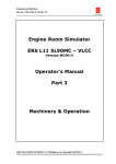
1
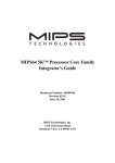
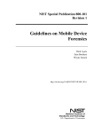
▲
Application Note
C OM P UT I NG
This application note describes protocol tests for the UMTS Iu interface between the Radio Network Controller
(RNC) and the Core Network (CN). It is the first in a series of documents on third-generation (3G) wireless
networks. Each note addresses one of the new network interfaces and provides guidelines for equipment
designers, manufacturers, operators and maintenance personnel to meet the measurement challenges with
testing solutions. Examples are given in this document for testing:
• Messaging and procedures on the Radio Access Network (RANAP)
• Mobile Radio Interface Layer 3 (CC/MM/GPRS MM/GPRS SM)
• Traffic channel signaling (AAL2 layer3)
• Tunneling (GTP-U).
Due to space limitations, only brief descriptions are presented here. Complete detailed information needed to
perform these and other tests can be found in the user handbooks for the K1297 and K1205 Protocol Testers
and in other training materials. Please contact Tektronix sales support to obtain the most recent information.
V I DE O
▲
Protocol Testing in the 3G Wireless Network
T E L E C OM
Testing the UMTS
Iu Interface
Testing the UMTS Iu Interface
▲
▲
Application Note
Table of Contents
1.
Testing the UMTS Iu Interface
INTRODUCTION – THE Iu INTERFACE AND PROTOCOLS ..................................................................................................................................................3
1. Introduction – The Iu Interface and
Protocols
Application Note
All traffic over the Iu interface uses the Asynchronous Transfer Mode (ATM) as
the physical transport technology, regardless of the data source. As a result, all
data will be segmented into 53-byte ATM-cells and transported
1.1. TRANSPORT PROTOCOLS FOR THE CONTROL PLANE ........................................................................................................................................3
1.2. TRANSPORT PROTOCOLS FOR THE USER PLANE ..............................................................................................................................................3
2.
This document describes test applications for the Iu interface as it was defined
by 3GPP at the end of 1999 (UMTS Rel. ‘99). Change requests have been
1.3. CONTROL PROTOCOLS FOR CALL CONTROL, SESSION AND MOBILITY MANAGEMENT..........................................................................................4
introduced and new features have been proposed every three months since
1.4. PROTOCOLS FOR USER TRAFFIC ....................................................................................................................................................................4
that definition was adopted, so it is possible that there will be revisions in more
MEASUREMENT CHALLENGES AND SOLUTIONS ............................................................................................................................................................4
Monitoring ............................................................................................................................................................................4
2.1.2.
Simulation ............................................................................................................................................................................5
2.1.3.
Emulation ..............................................................................................................................................................................5
2.1.4.
Conformance Testing. ............................................................................................................................................................5
2.2. CONFIGURING THE TEST EQUIPMENT ..............................................................................................................................................................6
Transport protocols for the control plane consist of the SSCS signaling
The Iu interface is defined in the 3GPP document series TS25.410-419. Iu is
subdivided into two different interfaces: Iu-CS for the circuit switched domain
and Iu-PS for the packet switched domain. Figures 1 and 2 show the protocol
stacks for each of the Iu interfaces.
datagrams. Loss of signaling messages can be detected and
retransmitted. SCCP is used to setup specific connections for the
connection-oriented communications. Iu normally uses the connection-
The protocols can be grouped according to their usage into:
oriented mode.
Hardware Connection Issues ....................................................................................................................................................6
• transport protocols for control plane
2.2.2.
Setting the Operating Parameters ............................................................................................................................................7
• transport protocols for user plane
MTP3b handles the routing and traffic management function for upper
2.2.3.
Defining Protocol Stacks ........................................................................................................................................................7
• control protocols for call, session, mobility management
layer protocols. It delivers messages to the destination point and
2.2.4.
Defining Emulation Parameters ................................................................................................................................................8
• protocols for user traffic
2.3.2.
manages the load sharing mechanism for the operation. MTP3b is
responsible for routing messages within a network with one operator;
SCCP routes messages beyond the board of an operator. While the
Simulation of AAL2 layer 3 ......................................................................................................................................................9
Radio
Network
Control
Plane
Emulation of AAL2 layer 3 ....................................................................................................................................................11
Transport
Network
Control
Plane
User
Plane
Data
Services
RANAP
AAL2L3
RLP
SCCP
STC
CC/MM/GPRS
MM/GPRS SM
2.4. TESTING RANAP AND DMTAP ........................................................................................................................................................................12
connections between the RNC and Core Network nodes are shown here
User
Plane
Voice
Services
as point-to-point, these connections could also be incumbent networks
consisting of several interim nodes.
TAF
AMR Codec
Iu UP
2.5. TESTING OF THE GTP-U PROTOCOL ..............................................................................................................................................................13
MTP3-b
SSCF-UNI
CONCLUSION ..............................................................................................................................................................................................................14
The most logical approach for Iu-PS would be to use the IP protocol stack
SSCOP
to transport the control signaling information. For this reason, the Internet
AAL2
AAL5
APPENDIX I ................................................................................................................................................................................................................15
Engineering Task Force (IETF) has proposed to replace SSCS and MTP3b
ATM
4.1. RECOMMENDED DOCUMENTS AND STANDARDS ............................................................................................................................................15
with M3UA and SCTP protocols on top of UDP/IP. Since this protocol stack
▲
4.2. GLOSSARY ..................................................................................................................................................................................................16
5.
ensure the signaling links between network nodes with numbered
2.2.1.
2.3.1.
4.
protocols (SSCOP and SSCF) as they are used in broadband networks to
different control signaling protocols, enabling both connectionless and
2.3. TESTING AAL2 LAYER 3 ..................................................................................................................................................................................9
3.
1.1. Transport Protocols for the Control Plane
recent releases of the standard.
2.1. SELECTING THE APPROACH – MONITORING , SIMULATION, EMULATION, CONFORMANCE ....................................................................................4
2.1.1.
asynchronously.
is still under development, there are no application tests for it in this
Figure 1: Iu-CS protocol stack
release of the note.
APPENDIX II – UMTS – Entering the Third Generation of Mobile Networks ................................................................................................................20
Radio Network
Control Plane
Transport Network
Control Plane
User Plane
CC/MM/GPRS MM/GPRS SM
IP
RANAP
Iu UP
1.2. Transport Protocols for the User Plane
SCCP
MTP3-b
M3UA
SSCF-NNI
SCTP
GTP-U
UDP
SSCOP
IP/UDP
AAL5
IP
AAL5
ATM
All signaling traffic for the control plane at the Iu interface is based on
AAL type 5. Signaling messages are packet data with variable lengths.
However, transport protocols for the user plane use both AAL5 and AAL2
(AAL5 for packet data, AAL2 for circuit-switched transmission).
▲
2 www.tektronix.com/commtest
Figure 2: Iu-PS protocol stacks
www.tektronix.com/commtest
3
Testing the UMTS Iu Interface
Testing the UMTS Iu Interface
▲
▲
Application Note
Application Note
For circuit switched data, the Iu User Plane (Iu-UP) protocol is used to
domain (Fax) in order to ensure compatibility with the existing network. IP
Interface monitoring can collect data and present results in
2.1.4. Conformance Testing
initialize and control the connection Rate Control, Time Alignment and
incorporates hundreds protocols used in the Internet and computer world.
the following way:
Standards allow different manufacturers to develop systems which
Handling of Error Events in accordance with the requested QoS
• data review for evaluation: The storage of measured data for
parameters. Circuit switched data are usually real time transmissions
such as voice or video streams.
Packet data are transported using GTP-U, UDP and IP protocols in the
packet switched domain of the network. In this domain, the Iu-UP
2. Measurement Challenges and Solutions
2.1. Selecting the Approach – Monitoring,
Simulation, Emulation, Conformance
subsequent review and analysis. The amount of data is
an implementation is declared conformant when its capabilities and
normally reduced through the filtering of specified events
external behavior meet those defined in the referenced standards.
(such as abnormal call termination), the use of statistical
Conformance testing is the verification process that determines
methods or the selection of specific conditions (tracing data at
whether a system or an implementation is conformant. While
a defined address, tracing a call set-up, etc.).
specific conformance tests are defined in UMTS for the air interface
(see 3G TS 34.xxx), conformance tests of the remaining UTRAN
protocol is in transparent mode and the GTP-U portion of the GTP
protocol is responsible for the data transmission. RANAP controls the
GTP-U channels – each GTP-U tunnel refers to a single mobile user
identified by the tunneling ID. The QoS parameter can be assigned to the
GTP-U tunnel. IP is used to address the GTP-U entity. Only four GTP
messages are used to ensure data traffic.
can interoperate and exchange and handle information. A system or
Nearly all measurement situations can be considered in three categories
2.1.2. Simulation
with related approaches. Even though there are situations where two or
Simulation is the representation or imitation of a process or system
more approaches could be applied to the same interface, the first steps
by another device. In a test environment, a simulator can be used in
in protocol testing should always be to determine the characteristics of
place of a network element or a part of the network to produce
the system under test and the test objectives.
desired conditions. For instance, when testing an RNC, the test
interfaces are still dependent upon mutual agreement between
manufacturers, operators, and measurement suppliers.
equipment can simulate the Core Network behavior, keeping the
1.3. Control Protocols for Call, Session and Mobility
Management
➔Do you have a living network that you should not, or are not,
allowed to influence?
Use the non-intrusive Monitoring approach
radio interface layer 3 represents the highest layer control function. It
handles the communication between core network and mobile handsets
and determines Handover, Location Update, Authentication and Call
conformance testing where standardized conditions are
Use the Simulation/Emulation approach.
applied to the NE.
• To substitute missing network elements or parts of a
RANAP carries out transmission activities based on the control decisions.
equipment?
For example, RANAP manages the Radio Access Bearer (RAB), which can
Use the Conformance approach
weak points of an item can be discovered in the development
2.1.1. Monitoring
used to setup, maintain and release user channels for the circuit
Monitoring is the process of collecting data from the interface using
switched domain. AAL2 layer 3 also handles the layer management
either the K1205, a pure monitoring device, or the K1297, which
function, which takes care of the transport layer itself.
can also perform simulation and emulation. The major objectives for
monitoring are:
• to get an overall view of the actual performance level
4 www.tektronix.com/commtest
process, before introducing it to an operating network.
2.1.3. Emulation
Emulation is a higher form of simulation where the behaviors of
selected layers of communication protocols are simulated
• to determine a possible need for an improvement
• to discover the differences between specified/ predicted
RLP are used to support data applications within the circuit switched
a realistic operating environment for the item under
• To save development and installation costs. The strong and
mobile user. RANAP initiates, modifies and releases RAB. However, the
packet data. Codec is usually not addressed in protocol testing. TAF and
network during the development process. Simulation creates
development.
be seen as a logical connection over the Iu interface related to a specific
User traffic protocols are embedded in Codec for voice (AMR) and IP for
will perform in the field. Simulations are also used for
stimulated?
➔Do you need to verify compatibility with standards or with other
1.4. Protocols for User Traffic
element (NE). Normal and abnormal situations are specified
environment allows the operator to predict how well the NE
➔Do you have a ‘dead’ node or system that needs to be externally
Handling.
control of the real physical connection is done by AAL2 layer 3, which is
• To get information about the dependability of a network
and simulated, and the NE’s ability to cope with the simulated
Control protocols for circuit-switched transmission are AAL2 layer 3,
mobile radio interface layer 3 (CC/MM/GPRS MM/GPRS SM). The mobile
RNC independent of the network. Simulators are used:
characteristics
• to improve predictions of behavior and potential problems
automatically and in conformance with standards. For instance, the
simulation of the Iu RANAP is based on an emulation of the
corresponding lower layers. While the lower layers are defined to
act as specified, the simulated layer can be used to deliberately
add faults to test an element’s ability to handle them.
www.tektronix.com/commtest
5
Testing the UMTS Iu Interface
Testing the UMTS Iu Interface
▲
▲
Application Note
Application Note
2.2.1. Hardware Connection Issues
Note: For Monitoring applications, you may proceed to capturing and
analyzing data after you have completed the hardware portion of the
Securing the proper cables is often a major issue for connecting to
tester configuration (Step 2.2.2).
the SUT. There are many different connectors and cables that it is
nearly impossible to predict what you will need in advance. To be on
the safe side, you should assume that none of the standard cables
2.2. Configuring the Test Equipment
delivered with the test equipment is the proper one and check to
see that you have the necessary adapters to suit each SUT.
Adapters for STM1 optical interfaces are provided with the K1297
Figure 3 shows two diagrams that illustrate how to connect the K1297
to overcome the problem for those connections.
with the system under test (SUT).
Another issue is the mode of operation (single- or multi-mode).
Even though the K1297 interface boards can handle both modes,
Simulation/Emulation
the receiver of the system under test could be overpowered if it
Figure 4: Dialog box for physical interface
ensure a stable multi-mode connection.
▲
K-1297
▲
were operated in multi-mode. Power reduction should be inserted to
Figure 6: Simulation pipeline and Emulations Scenario Editor
the digital data. Thousands of virtual connections can exist in a
Tx
single ATM physical connection, so it is critical to know the VPI/VCI
Rx
in order to configure the correct logical links between the test
Active Monitoring
instrument and the lower layer. Figure 5 shows the window for
SUT
K-1297
configuring the VPI and VCI. This window also allows the assignment
of a protocol stack to each of the logical links. The “Browse”
Tx = Transceivers
Rx = Receiver
Tx
Tx
function enables the selection of predefined protocol stacks for this
Rx
Rx
purpose.
SUT
SUT
The hardware configuration is now completed, and
Monitoring applications can be started.
K-1297
Passive Monitoring
2.2.3. Defining Protocol Stacks
For Simulation/Emulation applications, the first step is to create a
▲
K-1297
Figure 5: LDS settings for the ATM link
2.2.2. Setting the Operating Parameters
Once the equipment is physically connected, parameters for the
fiber or electrical connections must be set to conform to the SUT.
Figure 4 shows an example of the parameter windows where values
Monitoring Ports
and options are selected. To view this window, select “Cards
K-1297
simulation pipeline. A protocol emulation stack can be defined for
each of the pipelines using the “Emulation Scenario Editor” (Figure
6). The emulation protocols are stacked together by logically
connecting the upper-layer and lower-layer service access points to
represent the protocol instances for each communication
connection.
Overview” in the main dialog box of the K1297. Detailed
descriptions of the parameters are included in the user manual.
“Logical Data Source” (LDS) represents the configured physical links
which can be connected to the upper layer protocols. In the
The most important settings are the “VPI,” virtual path id, and “VCI,”
K-1297
virtual channel id, which are used to address the connections for
example shown in Figure 6 two protocol emulations are selected
and connected, NNISSCS and NNIMTP3b. NNISSCS emulates the
▲
Figure 3: Connecting the K1297 with the system under test (SUT).
6 www.tektronix.com/commtest
www.tektronix.com/commtest
7
Testing the UMTS Iu Interface
Testing the UMTS Iu Interface
▲
▲
Application Note
Application Note
and tested.
into specific primitives according to the signaling transport in use, as
Detailed descriptions of each of the emulations can be found in the
defined in Q.2150.1 and Q.2150.2. This can be the MTP3b for the Iu and
directory c:\K1297\hlp. Please refer to these files to configure the
Iur interfaces, or the SSCS for the Iub interface.
emulations completely and accurately.
Depending on test objectives, the K1297 provides either Simulation or
Emulation for AAL2 layer 3. The following sections provide guidelines for
each approach.
2.3. Testing AAL2 layer 3
This section describes guidelines for AAL2 layer 3 Simulation/Emulation.
This protocol layer is responsible for signaling traffic channels on behalf
of users such as RANAP. Figure 11 shows the logical structure of AAL2
layer 3 protocol.
2.3.1. Simulation of AAL2 layer 3
The K1297 provides a “Message Building System” to compose
correct and incorrect messages and a “Message Sequence Chart”
to describe test sequences graphically. A predefined configuration
▲
▲
Figure 7: Parameters of the SSCP emulation
Figure 9: Parameters of the SSCOP emulation
Timers need to be defined for SSCS (SSCOP/SSCF) in order to
specify the quality of the SSCOP service that is provided to the
The Access Link Control Application Part (ALCAP) consists of three parts:
set for AAL2 layer 3 Simulation can be loaded by selecting
Layer Management, AAL type 2 Signaling, and Signaling Transport
“c:\k1297\umtsaal2l3.s.” This configuration is designed to provide
Converter (STC). STC converts the AAL2 layer3 messages or primitives
an environment for back-to-back testing.
upper layers. For example, the timer for keeping the connection
alive addresses a critical issue when configuring SSCS for Proving.
Defining routing information, such as DPC, OPC and link set,
AAL type 2 served user
configures MTP3b and provides the signaling information to
(Note 2)
(Note 2)
AAL type 2 served user
destinations in the network. SIO values are needed to forward the
messages to the upper service access points (SAPs), so an SIO
SAP
bits are defined.
SAP
AAL type 2 signaling
Primitives
and OPC is defined with 14 bits, except in North America where 24
Primitives
AAL type 2
signaling messages
AAL type 2 signaling
SAP
SAP
Signaling Connection Control Part (SCCP) ensures the connection
▲
Figure 8: Parameters of the MTP3b
Service Specific Convergence Sublayer for the Network-NodeInterface, while NNIMTP3b is the broadband MTP layer 3. These
emulations contain the AAL2 layer 3 protocol information.
Generic Primitives
database beyond the board of an operator (for global title
Signaling transport converter
connectionless services and operates on a database of subsystems
SAP
Signaling transport
subsystems and users must be defined. In order to test RANAP, for
Primitives
Specific Primitives
Signaling transport
Primitives
example, we need to set the subsystem number (SSN) to 142
(Figure 7). Once these protocols are configured for use, Mobile
▲
Network control protocols can be put on top of this protocol stack
8 www.tektronix.com/commtest
SAP
Specific Primitives
Before SCCP can be put into operation, parameters for supported
delivered with pre-configured emulation (Figure 9).
Signaling transport converter
translation). SCCP emulation provides both connection-oriented and
2.2.4. Defining Emulation Parameters
“Parameter View” for each protocol. Most protocol test functions are
Generic Primitives
for signaling protocol, especially for messages accessing the
and users.
Parameters for configuring the protocol emulations are listed in the
Layer management
must be named for each of the MTP3b links. The length of the DPC
Primitives
SAP
SAP
upper layer protocols (Figure 8). A destination point code (DPC)
This Recommendation
(Note 1)
Primitives
Layer management
value must be defined for each SAP depending on the expected
Figure 10: Protocol structure of AAL2 layer 3
www.tektronix.com/commtest
9
Testing the UMTS Iu Interface
Testing the UMTS Iu Interface
▲
▲
Application Note
Figure 14: Message Sequence Chart
When the previous steps are completed, messages for AAL2 layer 3
Now, we are ready to develop test scenarios with the K1297
services for protocols, such as RANAP, and for layer management
“Message Sequence Chart” (MSC). An MSC can be created as
can be created and modified. Figure 13 displays the window for
shown in Figure 14. TC represents the test tool (in this case, the
parameter definition of an ESTABLISH REQUEST message.
K1297) and IUT means implementation under test. The first
Messages for served users are:
▲
Figure 13: Parameter definition for an ESTABLISH REQUEST message
▲
▲
▲
Figure 11: Protocols in STK-umts_iu_cs-pool1.pdc
Application Note
Figure 15: An example of Simulation of AAL2 layer 3
This emulation will be described in greater detail in the next release
of this application note.
message shown in Figure 14 is the Establish Request message
enclosed in an MTP3_UserData_Req primitive.
- Establish Request
- Establish Confirm
A Forth language script is provided with the AAL2 layer 3 Software
- Release Request
Product. This script is loaded when the system configuration
- Release Confirm
“umtsaal2l3.s” is opened. The script includes messages that can be
sent very easily. In this example the IUT only contains the MTP
Messages for layer management are:
- Block Request
▲
Figure 12: Messages and primitives
emulation without user (AAL2 layer 3). Therefore, after the program
sends one of the messages, the MTP emulation of the opposite side
responds with UPU message (Figure 15).
- Block Confirm
You can either open an existing message pool or create a new one.
- Unblock Request
In addition to the Forth programming environment, which allows the
During the creation of a new message pool one appropriate protocol
- Unblock Confirm
development of Simulation test sequences, the K1297 provides the
- Reset Request
C-API interface for the programming of test scripts for AAL2 layer 3.
stack must be selected and linked with the pool. Figure 11
illustrates the protocols created in a message pool labeled “ STK-
umts_iu_cs-pool1.pdc”.
- Reset Confirm
- Confusion
2.3.2. Emulation of AAL2 layer 3
The Emulation of AAL2 layer 3 is set up to act and react
In order to create new messages and new primitives, the underlying
automatically to either Layer Management or protocols. For
emulation must be connected to the protocol by defining the
Once the necessary messages are defined, primitives to the lower
property of the protocol (Figure 12).
layer protocol should be created for each of the receiving and
transmission messages.
10 www.tektronix.com/commtest
example, RANAP procedures such as RAB Assignment Request, IuRelease Complete and Iu Bearer Reconfiguration will trigger AAL2
layer 3 emulations for setting up or releasing an AAL2 connection.
www.tektronix.com/commtest 11
Testing the UMTS Iu Interface
Testing the UMTS Iu Interface
▲
▲
Application Note
Application Note
2.4. Testing RANAP
RANAP is much more complex than AAL2 layer 3 and therefore requires
more sophisticated testing. Supported RANAP messages and elementary
procedures are shown in the following tables.
Elementary Procedure
Unsuccessful Outcome
Response Message
Successful Outcome
Response Message
Initiating Message
Iu Release
Iu Release Command
Iu Release Complete
Relocation Preparation
Relocation Resource Allocation
Relocation Cancel
SRNS Context Transfer
Relocation Required
Relocation Command
Relocation Preparation Failure
Relocation Request
Relocation Cancel
Relocation Request Acknowledge
Relocation Failure
Security Mode Control
Data Volume Report
Security Mode Command
Security Mode Complete
Data Volume Report
Security Mode Reject
Data Volume Report Request
CN Information Broadcast
CN Information Broadcast Request
CN Information Broadcast Confirm
CN Information Broadcast Reject
Reset
Reset Resource
Reset
Reset Acknowledge
Reset Resource Acknowledge
SRNS Context Request
Figure 16: Packet Generation
▲
▲
Rest Resource
Relocation Cancel Acknowledge
SRNS Context Response
2.5. Testing of the GTP-U Protocol
Figure 17: Protocol stacks and parameter views
two Forth programs, UMTSPGEN.4th and UMTSPCOM.4th, are included
for both the transmission and receiving sides.
GPRS Tunneling Protocol for User Plane (GTP-U) consists of four
messages:
Elementary Procedure
UMTSPGEN sets the necessary header information for the different
Message
RAB Release Request
RAB Release Request
Iu Release Request
Relocation Detect
Relocation Complete
SRNS Data Forwarding Initiation
SRNS Context Forwarding from Source RNC to CN
Paging
Iu Release Request
Common ID
CN Invoke Trace
CN Deactivate Trace
Location Reporting Control
Location Report
Initial UE Message
Direct Transfer
Overload Control
Error Indication
Common ID
Relocation Detect
Relocation Complete
protocol layers such as IP, UDP and GTP-U. For a switch to accept the
generated packet, the header information must be set in accordance with
- Echo Request
the switch settings. Some parameters are defined by other signaling
- Echo Response
protocols in RANAP such as TEID (Tunneling Endpoint ID).
- Version Not Supported
The Packet Generator is an emulation with extended features like an
SRNS Data Forward Command
Forward SRNS Context
Paging
CN Invoke Trace
CN Deactivate Trace
Location Reporting Control
Location Report
Initial UE Message
Direct Transfer
Overload
Error Indication
- T-PDU
application supporting the following protocols: GTP-U (TS 29.060), UDP
(RFC 769), IP (RFC 791, 1483, 2225). Data packets can be generated for
each of these protocol layers. Figure 17 shows protocol stacks and
Echo-Messages check the availability of a link. T-PDU’s carry user data
between GTP-U Tunnel Endpoints.
The K1297 supports two GTP-U test objectives – you can test the GTP-U
protocol elements themselves or test the data services that GTP-U
provides. For the first purpose, GTP-U MBS and MSC can be used to
simulate the protocol by inserting correct or incorrect messages and
timers. These tests follow the same test sequences as the other protocols
(see Section 2.3, above).
Elementary Procedure
RAB Assignment
Initiating Message
Response Message
RAB Assignment Request
RAB Assignment Response x N (N>=1)
To keep messages as short as possible, RANAP uses the ASN.1 packed
Mobility Management, Call Control, GPRS Mobility Management and
encoding rules. A byte board is used to separate the message and
GPRS Session Management are provided on top of the RANAP.
12 www.tektronix.com/commtest
(C:\K1297\config\umts_pgen.s) loads this software for the user (Figure
16). In addition to the message pool and the necessary protocol stack,
▲
information elements.
The software tools “Packet Generator” and “Comparator” are provided to
test the GTP-U data services. A predefined configuration
Figure 18: Result of Packet Generation
www.tektronix.com/commtest 13
Testing the UMTS Iu Interface
Testing the UMTS Iu Interface
▲
▲
Application Note
corresponding parameter views. PKTGEN can be configured and run for
• Monitor and emulation software for 8xSSCOP
up to 16 data links by using the configuration tool within the “Parameter
• TTCN Compiler for Conformance Test Suites
View.” In the example, Forth scripts are used to configure and to start
• Executable Test Suites (SSCOP(SSCF), Q.2931, UNI3.1, Q.2763, MTPL3b)
4. Appendix I
4.1 Recommended Documents and Standards:
3G TS 23.110
UMTS Access Stratum Services and Functions
3G TS 25.301
Radio Interface Protocol Architecture
UMTSCOMP receives the data, collects statistical information and
3G TS 25.321
Medium Access Control (MAC) Protocol Specification
calculates delays. Figure 18 shows the results of a typical test.
3G TS 25.322
Radio Link Control (RLC) Protocol Specification
3G TS 25.323
Packet Data Convergence Protocol (PDCP) protocol
3G TS 25.324
Radio Interface for Broadcast/Multicast Services
3G TS 25.331
Radio Resource Control (RRC) Protocol Specification
3G TS 25.401
UTRAN Overall Description
3G TS 25.410
UTRAN Iu Interface: General Aspects and Principles
3G TS 25.411
UTRAN Iu interface Layer 1
3G TS 25.413
UTRAN Iu Interface: RANAP Signaling
3G TS 25.420
UTRAN Iur Interface: General Aspects and Principles
3G TS 25.423
UTRAN Iur interface RNSAP Signaling
3G TS 25.430
UTRAN Iub Interface: General Aspects and Principles
and emulation of IP packet generator and comparator; English documentation;
3G TS 25.433
UTRAN Iub interface NBAP Signaling
Requirements (7KK1220-0SCxx) >= V1.0 and ATM-HW
3G TS 29.060
3rd Generation Partnership Project; Technical
packet generation for a single data link.
• Support for AAL 3/4, AAL 5, STM 4, STM 1 optical/electrical/TP,
E3/DS3, E1/DS1, ATM 25.6 interfaces.
IETF RFC 2225
Classical IP and ARP over ATM
IETF RFC 2460
“Internet Protocol, Version 6 (IPv6) Specification.”
ITU-T I.361
B-ISDN ATM layer specification.
ITU-T I.363.2
B-ISDN ATM Adaptation Layer Type 2
ITU-T I.363.5
B-ISDN ATM Adaptation Layer Type 5
ITU-T Q.711
Functional description of the Signaling connection
The following software packages are available:
control part
ITU-T Q.712
• UMTS Monitor SW (G20) for Iu-PS user plane interface; incl.: GTP-U (TS29.060)
3. Conclusion
and IP as well as underlying protocols UDP/IP and IP over ATM; English
documentation; Required basic package >=V1.0 (7KK1220-0SCxx) and ATM-HW
The K1297 Protocol Tester is a powerful tool for the design, development and
deployment of new 3G networks. The K1297 is a comprehensive solution,
• UMTS Test SW (G20) for Iu control-plane; incl.: Emulations of SSCOP, MTP3B,
adding simulation and emulation capabilities and an enhanced graphical user
SCCP emulation and simulation of AAL2L3(Q.2630.1, Q.2150.2),
interface to the extensive monitoring functions of its predecessor, the K1205.
RANAP(TS25.413) and Mobile Radio Layer 3 (TS24.008); English documentation;
The K1297 is compact and configurable to help you meet a variety of
Required basic package >= V1.0 (7KK1220-0SCxx) and ATM-HW
measurement challenges with ease, including:
• protocol functional tests
• node simulations, where the entire protocol stack is emulated/simulated,
including the user plane.
• UMTS Test SW (G20) for Iu-PS user plane; incl.: simulation of GTP-U (TS29.060)
Service (GPRS); GPRS Tunneling Protocol (GTP) across
For additional information please also access our web site at www.tektronix.com/commtest.
ITU-T Q.713
Signaling connection control part formats and codes
ITU-T Q.714
Signaling connection control part procedures
ITU-T Q.715
Signaling connection control part user guide
ITU-T Q.716
Signaling Connection Control Part (SCCP) performance
ITU-T Q.2100
B-ISDN Signaling ATM Adaptation Layer (SAAL) overview description.
ITU-T Q.2110
protocol testing applications. All bundles include:
• Monitoring
ITU-T Q.2130
at the User Network Interface (SSCF at UNI)
ITU-T Q.2140
interfaces will follow in the near future. This document is also available at our
• Emulation
web site (www.tektronix.com), along with updates and related documents.
• Sample scripts for message sequences, message pools and predefined
Tektronix is committed to the most advanced test solutions for mobile
• Simulation Base software with Emulation Scenario Editor (ESE),
ETSI GSM 12.04
Digital cellular telecommunication system (Phase 2);
G. Sidebottom et al, “SS7 MTP3-User Adaptation Layer
networks. As mobile networks continue to evolve through GPRS, UMTS and
(M3UA draft-ietf-sigtran-m3ua-02.txt (Work In Progress),
cdma2000, we will keep you in the forefront with the latest testing products
IETF, 10 March 2000
Message Sequence Chart (MSC), Message Building System (MBS),
and methods.
PFE-Forth based interpreted scripting language
We welcome your comments and suggestions for improving these documents
draft-ieft-sigtran-sctp-v0.txt (Work In Progress), IETF,
and your ideas for developing other tools to help you meet the measurement
September 1999
To address the new ATM features in the UMTS, K1297/ATM Software includes:
• Monitor and simulation software for UNI (Q.2931 CS2.1, ATMF UNI3.1,
ATMF UNI4.0)
• Monitor and simulation software for NNI (Q.2761 - Q.2764 CS2.1, B-ICI 2.1)
14 www.tektronix.com/commtest
challenges of new wireless systems.
Interface (SSCF AT NNI).
ITU-T Q.2150.1
IETF SCTP
AAL type 2 Signaling Transport Converter on Broadband
MTP
ITU-T Q.2150.2
AAL Type 2 Signaling Transport Converter on SSCOP
(Draft)
Performance data measurements
IETF M3UA
B-ISDN ATM adaptation layer - Service Specific Coordination Function for Signaling at the Network Node
profiles) (ETR/ATM-1002)
defined by 3GPP in 1999. Updates and solutions for the new Iub and Iur
B-ISDN Signaling ATM Adaptation Layer - Service
Specific Coordination Function for Support of Signaling
Advanced Testing Methods (ATM); Tutorial on protocol
conformance testing (Especially OSI standards and
engineer who is interested in solutions for the UMTS Iu interface as it was
• Protocol simulation
emulation stacks
ETSI ETR 021
B-ISDN ATM Adaptation Layer - Service Specific
Connection Oriented Protocol (SSCOP).
the Gn and Gp Interface
This first release of the application note presents guidelines for the test
Definition and function of Signaling connection control
part messages
Specification Group Core Network; General Packet Radio
• node tests, where all messages belonging to a message group can be collected.
The K1297 features programming flexibility and a common platform for all
Appendix I
ITU-T Q.2210
Message transfer part level 3 functions and messages
using the services of ITU-T Recommendation Q.2140.
ITU-T Q.2630.1
AAL type 2 Signaling Protocol (Capability Set 1)
R. Stewart et al, “Simple Control Transmission Protocol,”
IETF RFC 791
Internet Protocol
IETF RFC 768
User Datagram Protocol
IETF RFC 1483
Multi Protocol Encapsulation over ATM Adaptation Layer 5
www.tektronix.com/commtest 15
Testing the UMTS Iu Interface
Testing the UMTS Iu Interface
▲
▲
Appendix I
4.2. Glossary
CDMA2000
3rd generation Code Division Multiple Access
GTP
GPRS Tunneling Protocol
Mbps
Megabits per second
Appendix I
1G
First Generation
CC
Call Management protocols
GTP-C
GTP Control
MBS
Message Building System
2G
Second Generation
CN
Core Network
GTP-U
GTP User
MC
Multi-Carrier
3G
Third Generation
CRNC
Controlling RNC (Radio Network Controller)
HLR
Home Location Register
MC-CDMA
Multi-Carrier CDMA
3GPP
Third Generation Partnership Project (of ETSI)
CS
Circuit Switched
HO/HoV
Handover
MCE
Multi-protocol Encapsulation
8PSK
Eight phase Shift Keying
CS-CN
Circuit Switched Core Network
HSCSD
High Speed Circuit Switched Data
ME
Mobile Equipment
AAL
ATM Adaptation Layer
CSE
CAMEL Service Environment
ICO
Intermediate Circular Orbits
MM
Mobility Management (protocols)
AAL2
ATM Adaptation Layer Type 2
CT
Conformance Test
IETF
Internet Engineering Task Force
MSC
Mobile Services Switching Center, Message Sequence
AAL5
ATM Adaptation Layer Type 5
D-AMPS
Digital AMPS
IMEI
International Mobile Equipment Identification
AC
Authentication Center
DCH
Dedicated Channel
IMT-2000
International Mobile Telecommunications 2000
MSS
Mobile Satellite System
ALCAP
Access Link Control Application Part
DECT
Digital Enhanced Cordless Telephone
IMUN
International Mobile User Number
MT
Mobile Telephone
AMPS
Advanced Mobile Phone Service
DL
Downlink
IN
Intelligent Network
MTP
Message Transfer Part
AMR
Adaptive Multi-Rate (speech codec)
DPC
Destination Point Code
IP
Internet Protocol
MTP3b
Message Transfer Part level 3 (broadband) for Q.2140
ANSI T1
Standards Committee T1 Telecommunication of the
DRNC
Drift Radio Network Controller
IPv4
IP version 4
NAS
Non Access Stratum
DRNS
Drift Radio Network Subsystem
IPv6
IP version 6
NBAP
Node B Application Protocol
DTE
Data Terminal Equipment
IS-95
Interim Standard ´95
NE
Network Elements
EDGE
Enhanced Data Rates for GSM Evolution
ISDN
Integrated Services Digital Network
NMT
Nordic Mobile Telephone
EFR
Enhanced Full Rate (speech codec)
ISP
Internet Service Provider
NNI
Network-Node Interface
EIR
Equipment Identity Register
ISUP
ISDN User Part
Node B
UMTS Base Station
ESE
Emulation Scenario Editor
ITU
International Telecommunication Union
NRT
Non-Real Time
ETSI
European Telecommunication Standards Institute
Iu
UTRAN interface between RNC and CN
NSS
Network Switching Subsystem
FDD
Frequency Division Duplex
Iub
UTRAN interface between Node B and RNC
O&M
Operation and Maintenance
FDMA
Frequency Division Multiple Access
Iu-CS
UTRAN interface between RNC and the circuit switched
OSA
Open Service Architecture
FEC
Forward Error Correction
domain of the CN
OSS
Operation Subsystem
FER
Frame Error Rate
UTRAN interface between RNC and the packet switched
PDC
Personal Digital Communication
domain of the CN
PDCP
Packet Data Convergence Protocol
Iur
UTRAN interface between two RNCs
PDH
Plesiochronous Digital Hierarchy
IUT
Implementation Under Test
PDN
Packet Data Network
IWF
Interworking Function
PDU
Protocol Data Unit
kbps
kilobits per second
PLMN
Public Land Mobile Network
LLC Relay
Logical Link Control - Relay
PMR
Private Mobile Radio
M3UA
MTP3 User Adaptation
PS
Packet Switched
MAC
Medium Access Control
PS-CN
Public Switched Core Network
MAP
Mobile Application Part
PSTN
Public Switched Telephone Network
American National Standards Institute
ARIB/TTC
Association of Radio Industries and
Business/Telecommunication Technology Committee
ASN.1
Abstract Syntax Notation One
ATM
Asynchronous Transfer Mode
AuC
Authentication Center
BEC
Backward Error Correction
BMC
Broadcast/Multicast Control
BSC
Base Station Controller
BSS
Base Station Subsystem
BTS
Base Transceiver Station
CAMEL
Customized Application for Mobile Enhanced Logic
CAP
GGSN
Gateway GPRS Support Node
GMM
GPRS Mobility Management (protocols)
CAMEL Application Part
CATT
China Academy of Telecommunication Technology
CBR
Constant Bit Rate (data stream)
CC
Call Control
CCITT
Comité Consultatif International Téléphonique et
GMSC
Gateway MSC
GMSK
Gaussian Minimum Shift Keying
GPRS
Telecommunication
CCS7
Common Control Signaling System No 7
CDMA
Code Division Multiple Access
16 www.tektronix.com/commtest
General Packet Radio Service
GSM
Global System for Mobile Communication
GSM-R
GSM Railway
gsmSCF
GSM Service Control Function
gsmSSF
GSM Service Switching Function
Iu-PS
Chart
www.tektronix.com/commtest 17
Testing the UMTS Iu Interface
Testing the UMTS Iu Interface
▲
▲
Appendix I
QoS
Quality of Service (ATM network channels)
TACS
Total Access Communication System
VBR
Variable Bit Rate (data stream)
QPSK
Quadrature Phase Shift Keying (or, Quaternary Phase
TAF
Terminal Adaptation Functions
VHE
Virtual Home Environment
Shift Keying)
TC
Transcoder
VLR
Visitor Location Register
RAB
Radio Access Bearer
TD-CDMA
Time Division-Code Division Multiple Access
VMSC
Visited MSC
RAN
Radio Access Network
TDD
Time Division Duplex
WCDMA
Wide band Code Division Multiple Access
RANAP
Radio Access Network Application Part
TDMA
Time Division Multiple Access
WLL
Wireless Local Loop
RLC
Radio Link Control
TD-SCDMA
Time Division - Synchronous CDMA
RLP
Radio Link Protocol
TEID
Tunneling Endpoint ID
RNC
Radio Network Controller
TETRA
TErrestrial Trunked Radio Access
RNS
Radio Network Subsystem
TIA
Telecommunications Industry Association
RNSAP
Radio Network Subsystem Application Part
TN-CP
Transport Network-Control Plane
RNTI
Radio Network Temporary Identity
TPC
Transmission Power Control
RR
Radio Resource
TRAU
Transcoder and Rate Adaptation Unit
RRC
Radio Resource Control
TS
Technical Specification
RRM
Radio Resource Management
TTA
Telecommunications Technology Association
RTT
Radio Transmission Technology
U MSC
U MSC Mobile Switching Center (the integration of the
SAAL
Signaling ATM Adaptation Layer
MSC and the SGSN in one physical entity (UMTS+MSC =
SCCP
Signaling Connection Control Part
UMSC)
SCTP
Simple Control Transmission Protocol
U MSC-CS
U MSC Circuit Switched
SDH
Synchronous Digital Hierarchy
U MSC-PS
U MSC Packed Switched
SDO
Standard Development Organization
U SSD
Unstructured Supplementary Service Data
SGSN
Serving GPRS Support Node
UDP
User Datagram Protocol
SIM
Subscriber Identity Module
UE
User Equipment
SM
Session Management protocols
UICC
UMTS IC Card
SRNC
Serving Radio Network Controller
UL
Uplink
SRNS
Serving Radio Network Subsystem
Um
GSM Air Interface
SS7
= CCS7 (Common Control Signaling System No. 7)
UMTS
Universal Mobile Telecommunication System
SSCF
Service Specific Coordination Function
UNI
User-Network Interface
SSCOP
Service Specific Connection Oriented Protocol
UP
User Plane
SSF
Service Switching Function
USIM
UMTS Subscriber Identity Module
STC
Signaling Transport Converter
UTRA
UMTS Terrestrial Radio Access
STM1
Synchronous Transport Module - level 1
UTRAN
UMTS Terrestrial Radio Access Network
SUT
System Under Test
Uu
UMTS Air interface
SW
Software
UWC-136
Universal Wireless Communication
18 www.tektronix.com/commtest
Appendix I
www.tektronix.com/commtest 19
UMTS – Entering the Third Generation of
Mobile Networks
UMTS – Entering the Third Generation of
Mobile Networks
▲
▲
Appendix II
5. Appendix II – Introduction to UMTS
defines enhancements and transitions for existing GSM networks.
Another newly defined UTRA mode - Multi Carrier (MC) - is expected to
Appendix II
The Iu, Iub and Iur interfaces are based on ATM transmission principles.
establish compatibility between UMTS and cdma2000.
UMTS – Entering the Third Generation of Mobile
Networks
The Public Land Mobile Network (PLMN) described in UMTS Rel. ´99
incorporates three major categories of network elements:
• GSM Phase 1/2 core network elements: MSC,VLR, HLR, AC and EIR
The Universal Mobile Telecommunication System (UMTS) is one of the most
The Radio Network Controller (RNC) enables autonomous Radio Resource
Implementation - New Network Elements and
Interfaces
(CSE)
Generation of Mobile Networks. UMTS allows many more applications to be
introduced to a worldwide base of users and provides a vital link between
UMTS standardization and development is moving very quickly, but several
• UMTS specific modifications and enhancements, particularly UTRAN
today's multiple GSM systems and the ultimate single worldwide standard for
The GSM Phase 1/2 PLMN consists of 3 subsystems: the Base Station
all mobile telecommunications (IMT-2000). The new network also addresses
Subsystem (BSS), the Network Switching Subsystem (NSS) and the Operation
the growing demand of mobile and Internet applications for new capacity in the
Subsystem (OSS). The BSS consists of the Base Station Controller (BSC), Base
overcrowded mobile communications sky. UMTS increases transmission speed
Transceiver Station (BTS) and Transcoding & Rate Adaptation Unit (TRAU). The
to 2 Megabits/s per mobile user and establishes a global roaming standard.
Station Controller (BSC), providing central control for the Radio Network System
(RNS) elements (RNC and Node Bs).
• GSM Phase 2+ enhancements: GPRS (SGSN and GGSN) and CAMEL
significant advances in the evolution of telecommunications into the 3rd
Management by UTRAN. It performs the same functions as the GSM Base
NSS consists of Mobile Services switching Center (MSC), Visitor Location
steps must be taken before we can enjoy global mobility at the remarkable new
The RNC handles protocol exchanges between Iu, Iur, and Iub interfaces and is
speeds. New network elements are being developed and adopted, while
responsible for centralized Operation & Maintenance for the total RNS with
existing network nodes are being extensively modified. All of these
access to the Operation SubSystem (OSS). Because the interfaces are ATM-
developments require the creation and integration of new software and
based, the RNC switches ATM cells between them. The user's circuit-switched
hardware modules that will then be manufactured, deployed, commissioned
and packet switched data coming from Iu-CS and Iu-PS interfaces are
and operated.
multiplexed together for multimedia transmission via Iur, Iub, and Uu interfaces
to and from the User Equipment (UE).
Register (VLR), Home Location Register (HLR), Equipment Identity Register (EIR)
and the Authentication Center (AC). The MSC provides functions such as
The UMTS standard can be seen as an extension of existing networks. Two new
switching, signaling, Paging, and Inter-MSC Handover. The OSS consists of
network elements are introduced in UTRAN, Radio Network Controller (RNC)
The RNC uses the Iur to autonomously handle 100% of the Radio Resource
Operation & Maintenance Centers (OMC), which are used for remote and
and Node B. UTRAN is subdivided into single Radio Network Systems (RNS),
Management (RRM), eliminating that burden from the Core Network. Serving
centralized Operation, Administration and Maintenance tasks.
where each RNS is controlled by a Radio Network Controller (RNC). The RNC is
control functions such as Admission, RRC connection to the UE, Congestion
reach global acceptance, 3GPP is introducing UMTS in Phases and Annual
UMTS (Rel. '99) incorporates enhanced GSM Phase 2+ Core Networks as a
connected to a set of Node B elements, each of which can serve one or several
and Handover/Macro Diversity are managed entirely by a single Serving RNC
Releases. The first release (UMTS Rel. '99), introduced in December of 1999,
platform, creating an entirely new network and protocol architecture with GPRS
cells.
(SRNC). If another RNC is involved in the active connection through an Inter-
Standardization
UMTS is being developed by 3GPP (Third Generation Partnership Project), a
joint venture of several Standards Development Organizations - ETSI (Europe),
ARIB/TTC (Japan), ANSI T1 (USA), TTA (South Korea) and CWTS (China). To
(General Packet Radio Services) and CAMEL
(Customized Applications for Mobile network
Enhanced Logic). The new networks will be
AUC
GMSC
PSTN
Gi
C
E
INTERNET
GGSN
H
landscape, enabling network operators to enjoy the
Gc
HLR
Gn
D
other PLMN
Gr
Gp
G
MSC
F
MSC
E
implementation.
Gf
VLR
SGSN
Iu-PS
Iu-CS
Iur
RNS
RNC
Abis
Iub
The most significant change in Rel. '99 is the new
RNS
RNC
Node B
Iub
Node B
Node B
Abis
Uu
Mobile
Phones
Handheld
Mobile
Devices
Node B
(CRNC) is used to define the RNC that controls Node Bs.
completely new designs. RNC will become the replacement for BSC and Node
B fulfills nearly the same functionality as a BTS. GSM and GPRS networks will
Node B is the physical unit for radio transmission/reception with one or more
be extended and new services will be integrated into an overall network that
cells. A single Node B can support both FDD and TDD modes, and it can be
contains both existing interfaces such as A, Gb, Abis and new interfaces that
co-located with GSM BTS to reduce implementation costs. Node B connects
include Iu, Iub and Iur.
with the UE via the W-CDMA Uu radio interface and with the RNC via the Iub
BTS
UMTS defines four new open interfaces:
UMTS Terrestrial Radio Access Network (UTRAN)
BSC
(UTRA), a W-CDMA radio interface for land based
BTS
responsible for the allocation of Code resources. The term Controlling RNC
ATM based interface. Node B is the ATM termination point.
that includes the UMTS Terrestrial Radio Access
BTS
adopt the UMTS requirement, but RNC, Node B and the handsets must be
Gb
Iu-PS
BSC
Existing network elements, such as MSC, SGSN and HLR, can be extended to
Gs
Iu-CS
A
improved cost efficiency of UMTS while protecting
their 2G investments and reducing the risks of
EIR
VLR
installed as islands within the GSM Phase 1/2
RNC Soft Handover, it is declared a Drift RNC (DRNC). The DRNC is only
BTS
communications. UTRA supports Time Division
• Uu: User Equipment(UE) to Node B (UTRA, the UMTS W-CDMA air
interface)
• Iu: RNC to GSM Phase 2+ Core Network interface (MSC/VLR or SGSN)
interface. It measures the quality and strength of the connection and
determines the Frame Error Rate (FER), transmitting these data to the RNC as a
Measurement Report for Handover and Macro Diversity Combining.The Node B
Duplex (TDD) and Frequency Division Duplex (FDD).
Iu-CS for circuit switched data
The TDD mode is optimized for public Micro & Pico
Iu-PS for packet switched data.
cells and unlicensed cordless applications. The
The main task of Node B is the conversion of data to/from the Uu radio
• Iub: RNC to Node B interface
is also responsible for the FDD Softer Handover. This Micro Diversity
combining is carried out independently, eliminating the need for additional
transmission capacity in the Iub.
FDD mode is optimized for wide area coverage, i.e.
▲
Figure 1: Overview of a UMTS network
public Macro & Micro cells. Both modes offer
flexible and dynamic data rates up to 2 Mbit/s.
20 www.tektronix.com/commtest
• Iur: RNC to RNC interface; not comparable to any interface in GSM
The Node B also participates in Power Control as it enables the UE to adjust its
www.tektronix.com/commtest
21
UMTS – Entering the Third Generation of
Mobile Networks
▲
Appendix II
power using DL TPC commands via the Inner Loop Power Control on the basis
landscape to full coverage during the next 10 years. Therefore, cross network
of UL Transmit Power Control TPC information. The predefined values for Inner
services must be managed by signaling protocols along with the UMTS specific
Loop Power Control are achieved from the RNC via Outer Loop Power Control.
services. For example, signaling must handle UMTS originated and GSM
terminated calls without interrupts. Protocol interactions across the networks
and inter-system handover are challenging tasks in the testing of mobility and
New Technology - New Testing Challenges
call control.
From the technology standpoint, testing UMTS interfaces presents a new set of
During the life cycle of UMTS, one of the most important aspects is quality
challenges. UMTS networks are based on the integration of ATM, IP and
management. Protocol Testers such as the K1297 help to shorten the
Mobile Network technologies. ATM brings "unlimited" bandwidth and QoS
development time, increase product quality and maintain the UMTS network.
limits, IP brings "unlimited" coverage, and Mobile Network brings "unlimited"
These instruments are essential partners for manufacturers and operators who
mobility. In addition, UMTS will use CDMA as the air interface technology,
are phasing into 3G mobile networks.
introducing different signaling procedures and different control signal levels
than those found in GSM and GPRS networks.
The K1297 Protocol Tester always refers to standardized UMTS interfaces. It
treats the System Under Test (SUT), whether a single network node or a subAlmost every ATM transmission speed from two Megabits/s up to STM4 (622
network, as if it were a black box. In both "Monitoring" and "Simulation &
Megabits/s) is defined for UMTS. Moreover, ATM has been designed to support
Emulation" modes, the tester compares the digital data streams that appear at
these speeds at specified quality of service (QoS) levels for traffic with
the interfaces with those defined in the standard.
guaranteed delays, losses and error rates. Constant bit rate (CBR) and variable
bit rate (VBR) data streams are assigned to VPI/VCI virtual channels to achieve
the required bandwidth. It is possible for a single connection to occupy the
entire physical bandwidth of a virtual channel, or even require hundreds or
thousands of virtual channels with smaller bandwidths.
ATM Adaptive Layers AAL2 and AAL5 protocols are the assembly and
reassembly mechanisms used within UMTS networks. AAL5 is primarily used
for packet data connections and signaling traffic, while AAL2 with its subchannels is used for voice and real time applications. Another issue for testing
is that AAL2 and AAL5 connections can occur simultaneously in the same
physical link.
While ATM provides virtual channels with QoS using either AAL2 or AAL5
protocols; IP distributes almost all applications over the network using
hundreds of different application protocols. From the testing point of view, IP
(at least IPv4) doesn't care about bandwidth or transmission quality. IP routes
the carried information to each destination independently, regardless of where
it is in the world. The challenges of testing IP are the large amount of data
and the variety of application protocols that it carries.
The UMTS enabled network is being grown from islands within the GSM
22 www.tektronix.com/commtest
tektronix.com/commtest
ASEAN Countries (65) 356-3900
Australia & New Zealand 61 (2) 9888-0100
Austria, Central Eastern Europe,
Greece, Turkey, Malta & Cyprus +43 2236 8092 0
Belgium +32 (2) 715 89 70
Brazil & South America 55 (11) 3741-8360
Canada 1 (800) 661-5625
Denmark +45 (44) 850 700
Finland +358 (9) 4783 400
France & North Africa +33 1 69 86 81 81
Germany +49 (221) 94 77 400
Hong Kong (852) 2585-6688
India (91) 80-2275577
Italy +39 (2) 25086 501
Japan (Sony/Tektronix Corporation) 81 (3) 3448-3111
Mexico, Central America & Caribbean 52 (5) 666-6333
The Netherlands +31 23 56 95555
Norway +47 22 07 07 00
People’s Republic of China 86 (10) 6235 1230
Republic of Korea 82 (2) 528-5299
South Africa (27 11) 651-5222
Spain & Portugal +34 91 372 6000
Sweden +46 8 477 65 00
Switzerland +41 (41) 729 36 40
Taiwan 886 (2) 2722-9622
United Kingdom & Eire +44 (0)1344 392000
USA 1 (800) 426-2200
From other areas, contact: Tektronix, Inc.
Export Sales, P.O. Box 500, M/S 50-255
Beaverton, Oregon 97077-0001, USA 1 (503) 627-6877
Worldwide Web: for the most up-to-date product information visit our web site at:
www.tektronix.com/commtest
Copyright © 2000, Tektronix, Inc. All rights reserved. Tektronix products are covered by U.S. and foreign patents, issued
and pending. Information in this publication supersedes that in all previously published material. Specification and price
change privileges reserved. TEKTRONIX and TEK are registered trademarks of Tektronix, Inc. All other trade names
referenced are the service marks, trademarks or registered trademarks of their respective companies. 11/00 BC/BT
2FW-14252-0