1
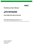
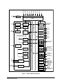
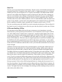
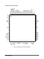
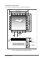
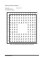
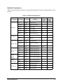
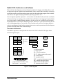
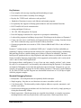
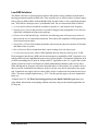
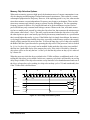
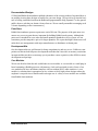
Rabbit 3000™ Microprocessor Data Sheet Rabbit 3000 Microprocessor Data Sheet Printed in U.S.A. ©2002 Rabbit Semiconductor • All rights reserved. Rabbit Semiconductor reserves the right to make changes and improvements to its products without providing notice. Trademarks Rabbit 3000 is a trademark of Rabbit Semiconductor. Dynamic C is a registered trademark of Z-World, Inc. Rabbit Semiconductor 2932 Spafford Street Davis, California 95616-6800 USA Telephone: (530) 757-8400 Fax: (530) 757-8402 www.rabbitsemiconductor.com Table of Contents Hardware Introduction 5 Block Diagram and Overview .............................................................................................................................. 6 I/O Electrical and 5-Volt Tolerant I/O .................................................................................................................8 Oscillator, Spectrum Spreader, Clock Divider, Clock Doubler ...........................................................................8 Battery-Backable Clock, Watchdog Timer, Periodic Interrupt, 32 kHz Clock ....................................................8 Timers ...................................................................................................................................................................9 Serial Ports ............................................................................................................................................................9 Memory Interface ...............................................................................................................................................10 Parallel I/O and Motion Control .........................................................................................................................10 Slave Port ............................................................................................................................................................11 I/O Bus and Auxiliary I/O Bus ...........................................................................................................................11 Electrical and Mechanical Specifications 13 Electrical Specifications .....................................................................................................................................13 Package Schematic and Pinout ...........................................................................................................................16 Package Mechanical Dimensions .......................................................................................................................17 Ball Grid Array Pinout (Tentative) .....................................................................................................................18 Rabbit Pin Descriptions ......................................................................................................................................19 Software Rabbit 3000 Architecture and Software 21 Processor Architecture ........................................................................................................................................21 Instruction Set .....................................................................................................................................................22 Development Environment/Dynamic C .............................................................................................................22 Key Features .......................................................................................................................................................24 Standard Debugging Features .............................................................................................................................24 Network Connectivity and TCP/IP .....................................................................................................................25 C Libraries ..........................................................................................................................................................27 Benchmarks ........................................................................................................................................................27 Background Low-EMI Solutions 29 Using the Clock Spectrum Spreader ...................................................................................................................30 Low-Power Solutions 31 Sources of Power Consumption .........................................................................................................................31 Options for Lowering the Clock Speed ..............................................................................................................31 Sleepy Mode .......................................................................................................................................................32 Memory Chip Selection Options ........................................................................................................................33 Battery-Backed Time/Date and Battery-Backed Memory .................................................................................34 Rabbit 3000 Data Sheet iii Support Sources of Support 37 Direct Support ....................................................................................................................................................37 Seminars/Trade Shows .......................................................................................................................................37 Visits ...................................................................................................................................................................37 Documentation/Designs .....................................................................................................................................38 Parts Store ...........................................................................................................................................................38 Development Kits ...............................................................................................................................................38 Core Modules .....................................................................................................................................................38 Rabbit 3000 Microprocessor User’s Manual Rabbit 3000 Data Sheet iv Rabbit 3000 Microprocessor and Embedded Design System The Rabbit 3000 is a modern 8-bit microprocessor that is the central element of a complete and fully supported embedded design system that includes development tools, software libraries, core modules, sample designs, a parts store, and readily available expert, human support. The Rabbit 3000 shares its instruction set and conceptual design with the successful Rabbit 2000. The instruction set is based on the Z80/Z180, but has been adapted to be C-friendly and to allow a megabyte of code space. Rabbit processors are fast with compact code. The Rabbit has an extensive array of on-chip peripherals including 6 serial ports, 56 parallel I/O pins, motion control interfaces, a time/date clock, glueless memory and I/O interfacing, a slave interface, and in-circuit programming. Low EMI features including a clock spectrum spreader eliminate schedule-wrecking EMI problems. Software development support is based on Z-World’s Dynamic C, and includes extensive libraries for Internet connectivity. Together with our software, the Rabbit is a very strong performers as our benchmarks show. Rabbit-based core modules can be used to speed development. Click the hypertext links for more information and consult the Rabbit 3000 Microprocessor User’s Manual for a complete specification. Rabbit 3000 Data Sheet 5 Block Diagram and Overview • The Rabbit 3000 is packaged in either a 128-pin LQFP or a 128-pin TFBGA package. • The operating voltage is nominally 3.3 V. • Process is 0.35 µm CMOS. • Maximum clock speed is 55 MHz (preliminary). • Normal Operating voltage is 3.3 V plus or minus 10%. • Normal Temperature Range is -55°C to +85°C. Rabbit 3000 Data Sheet 6 Data Buffer CLK /WDTOUT STATUS SMODE1 SMODE0 /BUFEN /IORD /IOWR /RESET RESOUT D[7:0] External Interface CPU XTALA1 XTALA2 Memory Management/ Control Spectrum Spreader Clock Doubler Fast Oscillator Global Power Save & Clock Distribution (8 bits) Address Buffer ADDRESS BUS A[19:0] Timer A Memory Chip Interface /CS2, /CS1, /CS0 /OE1, /OE0 /WE1, /WE0 Parallel Ports Port A PA [7:0] Port B PB[7:0] Port C PC[7:0] Port D PD[7:0] Port E PE[7:0] Port F PF[7:0] Port G PG[7:0] Serial Port A Asynch Synch Serial Serial Asynch Synch Bootstrap Bootstrap Timer B Asynch Serial IrDA 32.768 kHz Clock Input IrDA Bootstrap Watchdog Timer (8 bits) Real-Time Clock Serial Ports B,C,D DATA BUS CLK32K Asynch Serial Periodic Interrupt IA[5:0] I[7:0] INT0A, INT1A INT0B, INT1B External I/O Chip Interface External Interrupts Synch Serial Asynch Serial IrDA Serial Ports E, F Asynch Serial ID[7:0] TXA, RXA, CLKA, ATXA, ARXA HDLC SDLC Asynch Serial IrDA HDLC/SDLC IrDA TXB, RXB, CLKB, ATXB, ARXB TXC, RXC, CLKC TXD, RXD, CLKD TXE, RXE TCLKE, RCLKE TXF, RXF TCLKF, RCLKF Pulse Width Modulation PWM[3:0] Quadrature Decoder QD1A, QD1B QD2A, QD2B AQD1A, AQD1B AQD2A, AQD2B Input Capture Slave Port Slave Interface Bootstrap Interface PC[7,5,3,1] PD[7,5,3,1] PF[7,5,3,1] PG[7,5,3,1] SD[7:0] SA[1:0], /SCS, /SRD, /SWR, /SLAVEATTN Figure 1. Rabbit 3000 Block Diagram Rabbit 3000 Data Sheet 7 I/O Electrical and 5-Volt Tolerant I/O While the normal operating voltage is 3.3 V plus or minus 10%, lower operating voltages down to 1.5 V are acceptable, leading to lower power consumption, but the maximum clock speed will be reduced. Higher operating temperatures to 105°C are acceptable provided the junction temperature is kept below 125°C, the Rabbit 300 will experience greater device life stress. The possibility of failure is significantly higher at temperatures over 125°C. The preliminary maximum clock speed is 50 MHz for industrial conditions at 3.3 V plus or minus 10% over a temperature range from -55°C to +85°C. For commercial conditions, the preliminary maximum clock speed is 54 MHz at 3.3 V plus or minus 5% over a temperature range from -40°C to +70°C. Signal inputs except oscillator buffers are +5 V tolerant, meaning that voltages up to 5.5 V may be applied with only leakage currents. This makes it easy to interface +5 V devices that have a 2 V or 2.4 V switching level. This includes HCT CMOS devices as well as most memory devices designed to operate at 5 V. Signal outputs can generally drive 6 mA, sourcing or sinking, on a continuous DC basis. The current consumption is 60 mA at 30 MHz and 3.3 V, and is approximately proportional to the operating frequency and operating voltage. The die to ambient thermal impedance is 59°C/W at zero air flow (LQFP package). At 3.3 V, 50 MHz, and a current consumption of 100 mA, this would result in about 19°C of die self-heating. The clock speed is derated or uprated by approximately 1.2% for each 5°C of heating or cooling. Oscillator, Spectrum Spreader, Clock Divider, Clock Doubler An external oscillator can be used or a simple crystal circuit can be connected to the built-in oscillator buffer. Normally the external crystal or resonator has a frequency ½ the desired internal clock speed. The clock doubler circuit is used to double the input clock speed. The clock speed can be reduced dynamically by disabling the doubler or enabling the clock divider. This can be used to reduce power consumption. For extremely low power consumption, the CPU can be driven by the 32 kHz clock, which can be divided down as low as 2 kHz to further reduce power consumption (sleepy mode). When the 32 kHz clock is used, the main oscillator is normally turned off by the software. This saves about 2 mA of current. The clock spectrum spreader modulates the clock frequency, spreading the energy of the higher harmonics over a broader spectrum, thus greatly reducing radiated EMI in any particular band and generally giving a 15–25 dB advantage on FCC and CE EMI tests. Battery-Backable Clock, Watchdog Timer, Periodic Interrupt, 32 kHz Clock Normally an external 32.768 kHz oscillator is provided to the Rabbit 3000 to drive a number of special functions. Rather than having a built-in oscillator buffer, a suggested low-cost external circuit based on a “tiny logic” buffer is recommended. A battery-backable 48 bit clock can be used to keep track of the time and date. This is driven at 32 kHz and consumes approximately 3 µA when the recommended circuit is used. A separate power pin is provided for the battery-backable Rabbit 3000 Data Sheet 8 clock so that the clock may remain powered while the rest of the processor is powered down. A simple circuit requiring a single transistor can switch power from the power supply to the backup battery for the clock as well as for an external battery-backed RAM memory, if desired. The watchdog timer forces a processor reset after a settable delay when enabled, and if not “hit” within the delay time which ranges from ¼ to 2 seconds. This protects the system against infinite loops and other types of software or hardware faults. The watchdog time is driven by the 32 kHz clock. The periodic interrupt interrupts the processor 2048 times per second when enabled. This is driven from the 32 kHz oscillator. It may be used for any utility purpose and for accurate time keeping. Z-World software supports the use of this interrupt for a variety of purposes. The 32 kHz clock is used to generate an initial 2400 bps baud clock. The 32 kHz oscillator is also used to drive the first stage of the cold boot via Serial Port A hardware so that the boot may be accomplished without initially knowing the frequency of the main oscillator crystal. Once the boot is under way, the main oscillator frequency can be determined by comparing it with the 32 kHz oscillator. Timers There are 8 “A” timers named A1–A8. Each timer can divide by a factor from 1 to 256 using a reloadable count down register. Timer A1 serves as a prescaler for the other timers. Timers A2– A7 are used to generate a baud clock for the 6 serial ports. Timer A8 is used to drive the pulsewidth modulation and input pulse capture system. The “B” timer is used to generate precisely timed output pulses by means of a 10-bit counter and two comparision registers. When the timer matches the contents of the comparision register, a timing event occurs that can be used to trigger a change of state in a parallel-port output. Serial Ports There are 6 serial ports named A–F. The ports do not all have the same capabilities.The capabilities are given in the following list. • Asynchronous—Maximum baud rate 1/8th processor clock, 7 or 8 data bits, 9th address bit protocol, 1 or 2 stop bits, parity bit. IRDA support sending and receiving for direct connect to infrared transceiver. Adjustable interrupt priority. Supported by all 6 ports A–F. • Clocked Serial (SPI)—Transmits and receives 8 data bits clocked by separate clock line. Clock may be provided internally or externally. Full duplex possible. Easy interface to many serial devices, shift registers or programmable logic. The maximum data rate is the processor clock divided by 2 if an internal clock is used or the processor clock divided by 6 if an external clock is used. • Cold Boot—Serial Port A only may be used to cold-boot the processor remotely in conjunction with 2 mode pins that force the cold-boot mode when the processor exits the reset state. Initial communication is at 2400 bps controlled by the 32 kHz clock. Serial Port A is also used for software debugging, but may be used by user applications with some precautions. (It is also possible to cold-boot the processor using the SPI mode of Serial Port A, or by using the slave port in a parallel mode.) Rabbit 3000 Data Sheet 9 • HDLC/SDLC—Only Serial Ports E and F have the capability to operate with this synchronous protocol. The clock can be separate, generated locally or remotely, or embedded in the data signal. If the clock is embedded in the data signal, then a built-in digital phase-lock loop extracts the clock. The following 5 types of signal modulation can be used: NRZ, NRZI, biphase-level (Manchester), biphase mark (FM0), or biphase space (FM1). Serial Ports E and F have a 4-byte receive fifo compared to the 1-byte buffers on the other serial ports. This aids in handling the higher speeds often used for synchronous communication. CRC checking, bit stuffing, and other essential functions are handled by the hardware. The maximum clock speed using an embedded clock and the digital phase lock loop is 1/16th the processor clock speed. If a separate external clock is used, the maximum data rate is 1/6th of the internal processor clock. (Using a 12.352 MHz crystal doubled to 24.704 MHz, the T1 line speed of 1.544 MHz can be obtained using the phase-lock loop as well as standard baud rates with less than 1% error starting at 115,200 bps. A 16.384 MHz crystal will work for the 2.048 MHz E1 speed with small (1.23% max) standard baud errors.) Memory Interface The Rabbit 3000 has an easy-to-use memory interface that can directly connect up to 6 static memory chips, either flash memory or static RAM. There are 3 chip selects, /CS0, /CS1, and /CS2 that can be connected directly to the memory chip select pin. There are 2 pairs of output enables and write enables, /OE0, /WE0 and /OE1, /WE1 that can be connected directly to the corresponding memory chip pins. There are 20 address lines and 8 bidirectional data lines. The memory cycle is 2 clocks long for read and 3 clocks long for write. This results in exceptional stability for the memory bus timing, with no possibility of bus fights or critical setup or hold timings. Wait states may be added to the memory cycle in increments of 1, 2, or 4 clock periods. The address out time from the clock is very fast, in the range of 6–9 nanoseconds worst case, depending on address bus loading. This allows high clock speeds without exceptionally fast memory, for example, a 37 MHz clock speed with 45 ns flash memory with the spectrum spreader enabled. The spectrum spreader, in the common case, creates the need for 3 ns faster memory access time. The Rabbit 3000 supports separate instruction and data space (I & D space). This makes it possible to enlarge data memory without resorting to long addresses and pointers. Parallel I/O and Motion Control The Rabbit 3000 has 7 parallel ports, each with 8 bits, for a total of 56 lines. Many of the ports share functionality with other devices so, depending on usage, some ports may be preempted by other functions such as serial I/O, the slave port, or the auxiliary I/O bus. Generally the output pins can drive 6 mA when the supply is 3.3 V. Certain ports are input or output only. Others can be configured on an individual pin basis as inputs or outputs. Some ports can be configured with as open drain outputs. A number of ports have synchronized outputs that can be timed using the facilities of Timer B so as to locate output transitions at precise times. Pulse-width modulation and pulse input capture units are available at a number of ports, as are optical-encoder inputs. Certain lines on Parallel Port E can be used as interrupt triggering inputs. The Parallel Port E lines can also be configured as I/O chip select, read strobes, write strobes, or read/write strobes. Rabbit 3000 Data Sheet 10 Slave Port The slave port is an unusual and powerful facility. The slave port is an 8-bit bidirectional port and associated control lines. It appears to the outside world (i.e., another processor) to be 4 registers. Similarly, the slave port also appears to be 4 registers to the Rabbit. The Rabbit and the outside processor can exchange data using these registers at high speed. Each side of the exchange provides its own clocking, so the exchange is asynchronous. Using the slave port, an entire Rabbit microprocessor system can be made to appear to be an I/O device controlled by the 4 registers. This allows the user to make a Rabbit system be a slave to another Rabbit or other microprocessor system. As an example, a system can be set up that appears to be a simple I/O device, but actually has the capability to translate simple commands into a complex protocol such as TCP/IP. The slave port shares pins with Parallel Port A and certain pins on other ports. If the auxiliary I/O bus feature is used, it excludes the use of the slave port since they both rely on the same I/O pins. I/O Bus and Auxiliary I/O Bus I/O instructions on the Rabbit 3000 are the same as memory access instructions, except the instruction has a prefix byte that specifies that this is an I/O instruction. The I/O space is 64K in size, and is addressed by 16 address lines, compared to 1 megabyte and 20 address lines for the memory space. Separate synchronizing signals signal an I/O cycle: /IOW, /IOR. I/O cycles are 3 clocks long and can have 1, 6, or 14 additional wait states added. The I/O space is divided into 8 blocks of 8192 addresses. Wait states may be assigned separately for each block. In addition, pins on Parallel Port E can be programmed to provide I/O chip selects, read strobes, or write strobes that are enabled when an I/O cycle takes place in one of the 8192 address blocks. Internal devices use the first 256 I/O addresses, and the read or write cycles directed to internal devices are only 2 clocks in length. A dilemma faced by many microprocessor system designers is resolving the conflict between a fast memory bus that should have low address and data line loading, and the need to share the same lines with an I/O bus that is extensive and may run between mother and daughter boards. The Rabbit 3000 has an optionally enabled auxiliary I/O bus that resolves this dilemma. This bus uses Parallel Port A for 8 bidirectional data lines and Parallel Port B for 6 I/O address lines. Other lines are the same as used for regular I/O transactions. If the auxiliary I/O bus is enabled then every I/O cycle executes on both the main memory bus and on the auxiliary bus. Memory cycles are ignored by the auxiliary bus. The 6 address lines remain in the last state until another I/O cycle executes and the auxiliary I/O bus data lines are in a high-impedance state between I/O cycles. Having a separate I/O bus reduces EMI and ground bounce by limiting the fast memory bus to a few close in packages. Up to 64 registers may be addressed in any of the 8 blocks of memory for which I/O strobes are available. It is also possible to share the higher address lines with the memory bus. The higher lines have the advantage of not having as much switching activity as the loworder memory-bus-address lines. Rabbit 3000 Data Sheet 11 Rabbit 3000 Data Sheet 12 Electrical and Mechanical Specifications This section of the data sheet gives a concise and brief view of the electrical and mechanical specification. A more complete specification can be found in the Rabbit 3000 Microprocessor User’s Manual. Electrical Specifications Table 1. Electrical Specifications 3.3 V Operation (preliminary) Symbol Parameter Conditions Min Typ Max Unit 1.5 3.3 3.6 Volts -55°C 85°C deg C VDD Operating Voltage Temp Temperature Free Air MCLK Max Clock Freq -40°C to +70°C 3.3 V ±5% 0 54 MHz MCLK Max Clock Freq -55°C to +85°C 3.3 V ±10% 0 50 MHz Vin Input Voltage To meet switching speed standards 0.7 × VDD 5.5 volts Isink Sink Current VDD 3.3V, Vout 1.0V 6 mA Isrc Source Current VDD 3.3V, Vout 2.3V 6 mA Ileak Input Leakage 25C 0.01 uA Ileak Input Leakage 85C 0.5 uA Tadr Time to Address out from Clock standard 30 pf load Tdin Setup Time to Clock for Data 2 3 5 ns 1 ns Normal operating voltage for maximum clock frequency is 3.3 V, but operation down to 1.5 V is possible. Derating of maximum clock speed for increased temperature or decreased voltage: Derating Factor = [(VDD - 0.7)/3.0] × (1 - (T - 85) × 0.0025) Example: Operating voltage is 1.5 V and temperature is 70°C. The derating factor is given by: [(1.5 - 0.7)/3)] × (1 - (70 - 85) × 0.0025) = 0.277 Thus the maximum operating frequency is given by 54 × 0.277 = 14.96 MHz. Rabbit 3000 Data Sheet 13 P Oscillator 48% 52% Oscillator delayed and inverted Doubled clock Delay time 0.48P Example Write Cycle 0.52P 0.48P 0.52P Address / CS Data out write pulse early write pulse option Address / CS Example Read Cycle data out from mem output enb early output enb option Figure 2. Memory Bus Cycle Rabbit 3000 Data Sheet 14 T1 Tw T2 address I/O Chip Select Strobe I/O Read Cycle data I/O read strobe I/O Write Cycle data out I/O write strobe Figure 3. I/O Bus Cycles Rabbit 3000 Data Sheet 15 Rabbit 3000 Data Sheet PD1 PD0 RXF, PG3 TXF, PG2 RCLKF, PG1 TCLKF, PG0 VSSIO RESOUT VBAT ARXA, PD7 ATXA, PD6 ARXB, PD5 ATXB, PD4 PD3 PD2 /RESET /CS1 VSSIO CLK32K /WDIOUT SMODE1 SMODE0 86 12 85 13 84 14 83 15 82 16 81 17 80 18 79 19 78 20 77 A1 A2 A3 VDDCORE VSSCORE 21 76 22 75 23 74 24 73 25 72 /SCS, I7, PE7 I6, PE6 INT1B, I5, PE5 INT0B, I4, PE4 I3, PE3 I2, PE2 VSSIO 26 71 27 70 28 69 29 68 30 67 31 66 32 65 64 63 62 61 60 59 58 57 56 55 54 53 52 51 50 49 48 47 46 45 44 43 42 41 40 39 38 37 36 35 34 PF6, AQD2B, PWM2 PF5, AQD1A, PWM1 PF4, AQD1B, PWM0 PB7, IA5, /SLAVEATTN PB6, IA4 PB5, IA3, SA1 PB4, IA2, SA0 PB3, IA1, /SRD PB2, IA0, /SWR PB1, CLKA PB0, CLKB VDDIO XTALA2 XTALA1 VSSIO PA7, ID7, SD7 PA6, ID6, SD6 PA5, ID5, SD5 PA4, ID4, SD4 PA3, ID3, SD3 PA2, ID2, SD2 PA1, ID1, SD1 PA0, ID0, SD0 126 121 119 115 97 98 99 100 101 102 103 104 105 106 107 108 109 110 111 112 113 114 116 117 118 120 122 123 124 125 PF3, QD2A PF2, QD2B PF1, QD1A, CLKC PF0, QD1B, CLKD /WE1 A19 VDDIO VSSIO PF7, AQD2A, PWM3 127 128 VDDCORE VSSCORE D7 RCLKE, PG5 TCLKE, PG4 /IOWR /IORD /BUFEN 87 11 1 33 10 D6 D5 D4 D3 D2 VSSIO VDDIO D1 D0 A0 VDDIO CLK /CS2 STATUS /OE0 A10 /CS0 RXE, PG7 TXE, PG6 VDDIO, INT1A, I1, PE1 INT0A, I0, PE0 Package Schematic and Pinout 2 96 95 3 94 4 93 5 92 6 91 7 90 8 89 9 88 VSSIO /OE1 A11 A9 A8 A13 A14 VSSCORE VDDCORE A17 /WE0 A18 A16 A15 A12 VDDIO VSSIO A7 A6 A5 A4 PC0, TXD PC1, RXD VSSCORE VDDCORE PC2, TXC PC3, RXC PAC4, TXB PC5, RXB PC6, TXA PC7, RXA VDDIO Figure 4. Package Outline and Pin Assignments 16 Package Mechanical Dimensions Figure 5 shows the mechanical dimensions of the Rabbit LQFP package. 16.00 ± 0.25 mm 14.00 ± 0.10 mm 96 32 65 14.00 ± 0.10 mm 1 16.00 ± 0.25 mm 97 128 64 33 0.18 ± 0.05 mm 0.40 mm 1.40 ± 0.05 mm 0.10 ± 0.05 mm The same pin dimensions apply along the x axis and the y axis. 0.60 + 0.10 mm 0.15 mm 1.00 mm Figure 5. Mechanical Dimensions Rabbit LQFP Package Rabbit 3000 Data Sheet 17 Ball Grid Array Pinout (Tentative) Rabbit 3000 128 Thin Map TFBGA 10x10 Body, 0.8 mm pitch A B C D E F G H J K L M AT56C55-IZ1T 10 11 12 1 2 3 4 5 6 7 8 9 VDDIO VSSIO PF7 PF5 PB6 PB2 XTALA2 PA6 PA2 PF3 PF1 PF0 CLK /CS2 PF6 PF4 PB5 PB1 XTALA1 PA5 PA1 PF2 /WE1 A19 STATUS /OE0 A10 PB7 PB4 PB0 VSSIO PA4 PA0 VDDIO VSSIO /OE1 D7 PB3 VDDIO PA7 PA3 A11 A9 A8 A13 /CS0 VDDCORE VSSCORE D6 D5 D4 D3 A14 D2 VSSIO VDDIO D1 /WE0 A18 A16 A15 D0 A0 A1 A2 A12 VDDIO VSSIO A7 PE7 A6 A5 A4 PC0 A3 VDDCORE VSSCORE PE6 PE5 PE4 PE2 VSSIO VDDIO PE1 PE0 PG5 PG7 PG6 PG4 PE3 /WDTOUT /CS1 VSSCORE VDDCORE A17 VBAT PD4 PD0 PC1 VSSCORE VDDCORE /IOWR SMODE1 VSSIO PD7 PD3 PG3 PG0 PC2 PC3 /IORD SMODE0 CLK32K PD6 PD2 PG2 VSSIO PC7 PC4 /BUFEN /RESET RESOUT PD5 PD1 PG1 VDDIO PC6 PC5 Figure 6. Ball Grid Array Pinout Looking Through the Top of Package Rabbit 3000 Data Sheet 18 Rabbit Pin Descriptions Table 2 lists all the pins on the device, along with their direction, function, and pin number on the package. Table 2. Rabbit Pin Descriptions Pin Group Pin Name Direction Function Pin Numbers LQFP Pin Numbers TFBGA B1 CLK Output Internal Clock 2 CLK32K Input 32 kHz Oscillator In 49 /RESET Input Master Reset 46 RESOUT Output Reset Output 50 XTALA1 Input Main Oscillator In 113 B7 XTALA2 Output Main Oscillator Out 114 A7 ADDR[19:0] Output Address Bus various DATA[7:0] BiData Bus directional 19-18, 1510 /WDTOUT Output WDT Time-Out 43 Output Instruction Fetch First Byte 4 SMODE[1:0] Input Bootstrap Mode Select [44,45] /CS0 Output Memory Chip Select 0 7 Output Memory Chip Select 1 47 Output Memory Chip Select 2 3 /OE0 Output Memory Output Enable 0 5 /OE1 Output Memory Output Enable 1 95 /WE0 Memory Write Enables /WE1 Output Memory Write Enable 0 86 Output Memory Write Enable 1 99 /BUFEN Output I/O Buffer Enable 42 /IORD Output I/O Read Enable 41 /IOWR Output I/O Write Enable 40 Hardware CPU Buses Status/Control STATUS Memory Chip /CS1 Selects /CS2 Memory Output Enables I/O Control Rabbit 3000 Data Sheet 19 Table 2. Rabbit Pin Descriptions (Continued) Pin Group Parallel I/O Ports Pin Name Direction Function Pin Numbers LQFP PA[7:0] Input / Output I/O Port A 104-111 PB[7:0] Input / Output I/O Port B 116-123 PC[7:0] 4 In / 4 Out I/O Port C 75,74, 7166 PD[7:0] Input / Output I/O Port D 59-52 PE[7:0] Input / Output I/O Port E 33, 34,3126 PF[7:0] Input / Output I/O Port F 100-103, 124-127 PG[7:0] Input / Output I/O Port G 63-60, 3836 Power, Processor Core VDDCORE +3.3 V 8, 24, 72, 88 Power Processor I/O Ring VDDIO +3.3 V 1, 17, 33, 65, 81, 97, 115 Power Battery VBAT Backup +3.3 V or battery 51 Ground Processor Core VSSCORE Ground 9, 25, 73, 89 Ground Processor I/O Ring VSSIO Ground 16, 32, 48, 64, 80, 96, 112, 128 Rabbit 3000 Data Sheet Pin Numbers TFBGA 20 Rabbit 3000 Architecture and Software Many software development systems marketed as tools for developing embedded software lack an appreciation for the subtleties and instead blindly follow a model that is suited for an environment where an all-powerful operating system supervises the application program. But in embedded software the application program and the operating system are one. Our development platform, Dynamic C, is focused on the embedded world, and it has a multitude of features that have no analogy in the world of Unix or Windows. Our language-based multitasking is one example. Another language support is for the recovery of variables located in batterybacked RAM after a system upset. Watch expressions, which are C expressions entered at the console for debugging purposes, can include calls to functions and can be used to trigger hardware activity, something not found in other systems that execute watch expressions in the development platform host rather than in the embedded target. Processor Architecture The Rabbit’s registers are nearly identical to those of the Z180 or the Z80. The figure below shows the register layout. A F H L D E B C IP IX 8 / 16 bit registers IY SP IIR PC XPC A’ F’ H’ L’ D’ E’ B’ C’ Alternate Registers S Z x x x V x C F - flag register layout S-sign, Z-zero, V-overflow, C-carry Bits marked "x" are read/write. EIR A- 8-bit accumulator F - flags register HL- 16-bit accumulator IX, IY - Index registers/alt accum’s SP - stack pointer PC- program counter XPC - extension of program counter IIR - internal interrupt register EIR-external interrupt register IP - interrupt priority register Figure 7. Rabbit Registers Rabbit 3000 Data Sheet 21 Compared to the Z80, the XPC and IP registers are new. The XPC register is used to manage the extended megabyte of code memory. The EIR register is the same as the Z80 I register, and is used to point to a table of interrupt vectors for the externally generated interrupts. The IIR register occupies the same logical position in the instruction set as the Z80 R register, but its function is to point to an interrupt vector table for internally generated interrupts. An important feature of the Rabbit is multiple priority interrupts. The IIR register is used to implement interrupt priority at 3 levels, 1, 2 or 3 (highest). Instruction Set The Rabbit instruction set is identical to the Z80 and Z180, except that a few instructions have been eliminated and some important new instructions have been added. The changes generally improve the instructions set, especially from the standpoint of improving the quality and execution speed of compiler generated C code. The changes are summarized below: • Execution speed for a Rabbit 3000 is approximately 4x faster compared to a Z180 and 5x faster compared to a Z80 for C generated code. • 16 bit loads and stores relative to the stack pointer and index registers greatly improve C code. • New instructions make the alternate register set accessible and usable. • I/O device access is now performed by prefixed memory instructions rather than dedicated I/O instructions. Most memory access instructions can access I/O space instead of they are prefixed. • Long jumps and returns allow a full megabyte of code space. • Long memory address stores and loads allow accessing a full megabyte of data. • Instructions generally execute in 2 clocks per instruction byte except for an additional clock required for some instructions to compute a memory address. The 16 x 16 multiply requires 12 clocks. Development Environment/Dynamic C Dynamic C is an integrated development environment that is used to interactively develop code and perform debugging for Rabbit-based systems. Dynamic C itself runs on a PC under Windows. It communicates and controls a Rabbit-based system being used for software development in one of two ways, each way depending on the existence of a standard diagnostic/programming connector on the Rabbit-based target system. The standard programming connector is a 10-pin, 2 mm header that is connected to Serial Port A and certain lines used for initialization and handshaking. The programming connector, which adds only about $0.25 to the cost of the target system, allows remote reset, startup, program load, and program debug. It can also be used as a low-cost serial interface for field setup of a system by loading operating parameters, etc. The simplest method of connecting Dynamic C to a target system is to use a Rabbit programming cable. The programming cable uses a serial port on the PC to control the development process on the target. (Note that the programming cable previously supplied for 5 V Rabbit-2000-based systems is different from the programming cable used for Rabbit-3000-based systems.) Rabbit 3000 Data Sheet 22 A more general solution is to use a RabbitLink card, which may be used to interface the target system to an ethernet connector and thence to a network or the Internet to which the PC hosting Dynamic C is also connected. Debugging then takes place communicating using TCP/IP to the RabbitLink card and then via the programming cable to the target being debugged. A direct Ethernet crossover cable from the PC to the RabbitLink card may also be used. In either case, Dynamic C has complete control of the target and retains the ability to reset the targe and reload the software. 9-pin D connector Converter RS-232 logic level 10-pin header mates with target PC Programming Cable Rabbit-based target system Figure 8. Use of Programming Cable Figure 9. Z-World RabbitLink Board Dynamic C presents a graphical user interface that includes an editor, assembler, C compiler, and debugger. Unlike some competitive development systems, Dynamic C is built from the ground up for the embedded environment. Issues such as startup initialization, support for battery backed memory, and memory-based file systems are approached with the embedded environment in mind. A well known multitasking kernel, uCOS-2, is included with the full version of Dynamic C. However, Dynamic C also has built in language features that enable cooperative multitasking in a particularly simple and easy to understand way. Cooperative multitasking has substantial reliability and simplicity advantages over the traditional preemptive multitasking. Rabbit 3000 Data Sheet 23 Key Features • Fast compiler with one-step compiling and downloading to target • Full-feature source and/or Assembly-level debugger • Royalty-free TCP/IP stack with source code provided • Hundreds of functions in source-code libraries and sample programs • Exceptionally fast support for floating-point arithmetic and transcendental functions • RS-232 and RS-485 serial communication • Analog and digital I/O drivers • I2C, SPI, GPS, Encryption, File System • Powerful language extensions for cooperative or preemptive multitasking • Loader utility program to load binary images into Z-World targets in the absence of Dynamic C • Create your own source code libraries and augment on-line help by creating “function description” block comments using a special format for library functions • Generate programs that use as much as 512K of data in SRAM and 512K of code in Flash or EPROM Dynamic C’s enhancements over traditional UNIX style C compilers facilitate embedded programming. Language extensions include constructs for cooperative and preemptive multitasking and protecting writes to variables during power failures. Libraries for standard C functions, board-specific peripheral drivers, chip peripherals, and other features are included in source code format. Assembly-language programming is fully supported, and assembly code is easily mixed with C code for time-critical applications. Developing software with Dynamic C is easy. Users can write, compile, and test C code, Assembly code, or even intermixed C and Assembly code without leaving the Dynamic C development environment. Debugging occurs while the application runs on the target. Alternatively, you can compile your program to an image file for later loading. Dynamic C runs on PCs under Windows 95, 98, 2000, NT, ME, and XP. Programs are downloaded at baud rates of 115,200 bps or higher while the program compiles. Standard Debugging Features • Breakpoints—Set breakpoints that can optionally disable interrupts. • Single stepping—Step into or over functions at a source or machine code level. • Code disassembly—The disassembly window displays addresses, opcodes, mnemonics, and machine cycle times. • Switch between debugging at machine code level and source code level by simply opening or closing the disassembly window. • Watch expressions—Watch expressions are compiled when defined, so complex expressions including function calls may be placed into watch expressions. Watch expressions can be Rabbit 3000 Data Sheet 24 updated with or without stopping program execution and can be used to trigger the operation of hardware devices in the target. • Register window—All processor registers and flags are displayed. The contents of general registers may be modified in the window by the user. • Stack window—Shows the contents of the top of the stack. • Hex memory dump—Displays the contents of memory at any address. • STDIO window—printf outputs to this window, and keyboard input on the host PC can be detected for debugging purposes. Network Connectivity and TCP/IP The Rabbit can be connected to a network or the Internet and communicate in various ways with other devices, for example, a PC connected to the same network or another Rabbit-based system. The communication is performed using a series of protocols based on the Internet Protocol which sends packets in a certain format over the network. The Rabbit supports 2 methods for implementing a connection to a network: Ethernet and modem-PPP. These are shown schematically below. Ethernet connector Rabbit-based system IP over Ethernet Network Portal To Network Modem Rabbit-based system Asynchronous Serial Connection Telephone Network Internet Service Provider PPP Protocol Figure 10. Rabbit-Based System Connection to Network or Internet Although the portal to the network may be Ethernet, there may be a second connection using DSL, wireless, satellite link, etc. It is also possible to reduce the network to a single cable, connecting two devices together with an Ethernet crossover cable. The Internet Protocol is based on 32-bit addresses and is normally written as 4 numbers in the range 0–255 and separated by periods, for example, 245.23.65.42. This provides 4 billion address, but there are techniques that allow many devices to share the same address by means of numbered ports. There are 65536 possible ports. By using private local IP address on a local network up to Rabbit 3000 Data Sheet 25 65536 local IP addresses can be associated with each “real” Internet IP address of a gateway device to the local network. In this way a many embedded devices that are visible on the internet can be contacted by using both an IP address and a port number. TCP/IP is a complex communications protocol that may be used to send a stream of characters between 2 devices in a network. It is based on bundling the characters in packets and sending them to a remote station specified by IP address and port number. Lost packets and other errors are corrected by re-sending the packets. The protocol is capable of high sustained transfer speeds even though the time for a given packet to reach its destination may be quite long on the Internet, in the hundreds of milliseconds or more. Due to the error correcting capabilities it is quite reliable and robust. Dynamic C includes a TCP/IP “stack.” The stack is a library of C functions that may be included in the user’s program to implement network connections using TCP/IP. This opens many possibilities for Rabbit-based systems. For example two Rabbit-based systems or a Rabbit-based system and a PC can send each other messages over the Internet. The RabbitLink card described above is an example of a device that uses TCP/IP to communicate over a network. The messages between Dynamic C running on a PC and the target system being debugged are sent over a network using TCP/IP rather than over a programming cable connecting the PC to the Rabbit target system. There are a number of higher level protocols that use the TCP/IP protocol for communication. The HTTP protocol is the protocol used for browsing Internet web sites. Dynamic C’s libraries support the HTTP protocol. This allows a Rabbit-based embedded system to operate as a Web site so that Web browser software (usually running on a PC) can be used to communicate with and control an embedded system based on the Rabbit. Demos are located at: http://demo.zweng.com—explanation http://demo.zweng.com:8148/—the weather server This demonstration allows you to view the weather at Rabbit Semiconductor headquarters in Davis, California, U.S.A. A browser can also send control information to a target system by means of functions supported under HTTP such as screen buttons or fill in fields. The Rabbit libraries include protocols for sending and receiving e-mail. Thus an embedded system based on the Rabbit can receive instructions or send messages via e-mail. (SMTP an POP3 protocols.) The FTP protocol, supported for the Rabbit, is used for transmitting files is also supported. This allows the easy download of data from an embedded system to a PC or other system using a FTP file transfer program such as the Windows shareware program CuteFTP. The Telnet protocol, supported by Dynamic C libraries, is used to connect a terminal to a device. This is a convenient way to communicate from a PC to a remote embedded device for control or setup of parameters. There are many other protocols and features associated with the Rabbit network connectivity functionality which cannot be discussed in the space available here. Rabbit 3000 Data Sheet 26 C Libraries Dynamic C includes the standard C libraries the generally come with C compilers. These include libraries for character handling, for math and floating point, for formatting and printing and many other functions. Dynamic C supports a flash or RAM file system which allows the creation of file systems held in permanent flash or battery backed SRAM memory. This is useful for systems that must log or accumulate data. Dynamic C’s floating point support is notable for its exceptional speed. Very few 8 or 16 bit processors can challenge the Rabbit in this area due to the exceptional floating point support. A floating point add or multiply executes in about 7 microseconds with a 50 MHz clock speed. The library functions such as sine or square root are also very quick. For example a floating square root is computed in about 20 microseconds. Dynamic C libraries include a multitude of drivers to control the various peripheral devices of the Rabbit processor as well as to control various devices found on Z-World controller cards. One such device, for example, is the Realtek 8019 ethernet interface chip. Dynamic C includes a Fourier transform signal processing library. A fourier transform, transforming 1024 real samples into 512 complex frequencies requires only 33 milliseconds with a 50 MHz clock. The calculation is done with 16 bit integers using a block floating exponent and dynamic scaling for excellent dynamic range. Benchmarks The benchmarks below were measured for various comparable processors. The Dhrystone is an integer and logic operation benchmark. The Whetstone is a floating point math and library benchmark. The Sieve is a short benchmark that measures integer, logic and looping operations. The top practical or top obtainable clock speed was used. In order to obtain these speeds it is necessary to use fast RAM on the Rabbit or ez80. As can be seen, the Rabbit is superior in every category. . Table 3. Microprocessor Benchmarks AMD Rabbit 188ES 3000 @40 MHz @50 MHz Borland Dynamic C 3.31 C Dallas Zilog ez80 Phillips Zilog Z180 DS80C320 @40 MHz 80C51 (8051) @33 MHz Zilog C @ 33 MHz Dynamic C @33 MHz compiler Keil C Keil C Dhrystone 1.1 1000’s/sec 6,570 3,603 2,914 1,719 1,251 598 Whetstone 1000’s/sec 813 61 20 79 140 61 Sieve (milliseconds) 53 120 158 303 160 350 Operation/ Program Rabbit 3000 Data Sheet 27 Rabbit 3000 Data Sheet 28 Low-EMI Solutions The Rabbit 3000 has six powerful design features that greatly reduce problems encountered in passing government-sponsored EMI tests. These measures are so effective that it is almost impossible to have an EMI problem with the Rabbit 3000. For this reason we have applied the designation “The EMI-free microprocessor” to the Rabbit 3000. The six features that reduce EMI are: • A clock doubler allows external the oscillator to operate at ½ the internal clock frequency. • Separate power pins for the processor core and I/O ring prevents propagation of core noise to signal lines exiting the microprocessor package. • Gated clocks in the internal logic - blocks the clock driving parts of the processor clock tree that are not in use for a particular instruction. This reduces the amplitude of EMI generated by clock related current surges. • An auxiliary I/O bus limits loading and makes unnecessary the physical extension of fast data and address lines in system. • Bus architecture allows designs that don’t require routing clock out of processor. • A clock spectrum spreader reduces EMI amplitude derived from the clock by up to 25 dB. Electromagnetic interference (EMI) and elecrotromagnetic compatibility (EMC) represent a continuing problem for the embedded microprocessor system designer. Government regulations such as those surrounding the CE mark in Europe and FCC regulations in the U.S. require that certain digital systems be tested or certified not to radiate unintentional radiation (radio waves) above limits that depend on frequency and on the intended end use of the product. For example, devices that are used in an industrial environment, such as a factory, may not be subjected to any regulation. Limitations may apply to devices that will be used in a commercial environment such as an office. The most stringent regulations(e.g., FCC Class B) typically apply to devices intended for home use. Technical Note 221, PC Board Layout Suggestions for the Rabbit 3000 Microprocessor, provides further information on mitigating radiated emissions, and provides detailed guidelines for PCB layout. Rabbit 3000 Data Sheet 29 Using the Clock Spectrum Spreader The spectrum spreader is very powerful for reducing EMI because it will reduce all sources of EMI above 100 MHz that are related to the clock by about 15–25 dB. This is a very large reduction since it is common to struggle to reduce EMI by 5 dB in order to pass government tests. 15dB Strong Spreading 10 Normal Spreading 5 50 100 150 200 MHz 250 300 350 Figure 11. Peak Spectral Amplitude Reduction from Spectrum Spreader The spectrum spreader modulates the clock so as to spread out the spectrum of the clock and its harmonics. Since the government tests use a 120 kHz measurement bandwidth to measure EMI, spreading the energy of a given harmonic over a wider bandwidth will decrease the amount of EMI measured for a given harmonic. The spectrum spreader not only reduces the EMI measured in government tests, but it will also reduce the interference created for radio and television reception. The spectrum spreader has three settings under software control: off, normal spreading, and strong spreading. When the spectrum spreader is engaged, the frequency is modulated and individual clock cycles may be shortened or lengthened by an amount that depends on whether the clock doubler is engaged and whether the spectrum spreader is set to the normal or strong setting. The frequency modulation amplitude and the change in clock cycle length is greater at lower voltages or higher temperatures since it is sensitive to process parameters and is proportional to the switching speed. The spectrum spreader also introduces a time offset in the system clock edge and an equal offset in edges generated relative to the system clock. A feedback system limits the worst case time error of any signal edge derived from the system clock to plus or minus 20 nanoseconds for the normal setting, and plus or minus 40 nanoseconds for the strong setting at 3.3 V. The maximum time offset is inversely proportional to the operating voltage. The time error will not usually interfere with communications channels, except perhaps at the extreme higher data rates. More details on dealing with the clock variation introduced are available in the Rabbit 3000 Microprocessor User’s Manual. Rabbit 3000 Data Sheet 30 Low-Power Solutions The Rabbit 3000 has an extensive bundle of features aimed at low-power and extreme low power operation. Competitive processors often have virtually no low-power features or only crude features such as a sleep mode with an input to cause the processor to wake up in response to an external command. An associated feature is battery backup of memory and the time/date clock. Sources of Power Consumption The Rabbit 3000 is a static design and it consumes no current when the clock frequency is zero except for a small leakage current on the order of a few microamperes. When the clock is operating, current is needed to charge and discharge internal capacitances and to provide power for crossover current when CMOS gates transition and both the N and P transistors are momentarily conducting. The current consumed is proportional to both the operating frequency and the operating voltage. Cutting the operating voltage in half, from 3.3 V to 1.65 V, will reduce power by a factor of 4 since both voltage and current are cut by a factor of 2. The main oscillator that is built into the Rabbit 3000 is a special case because it operates in a linear mode of operation with an output signal resembling a sine wave more than a square wave. Most of the current consumed is due to crossover current during the slow transition of the output signal. The duty cycle of the crossover current is independent of frequency and as a result the current consumed by the oscillator is independent of frequency and is about 1 mA at 3.3 V. The current consumed by the oscillator is proportional to the square of the voltage above the gate threshold because as the voltage is lowered the crossover resistance increases due to less gate drive. The result is that oscillator power drastically decreases with voltage. If VDD is 1.65 V, the oscillator current drops from 1 mA to about 0.1 mA, and power drops by a factor of 20. Memories can be responsible for a substantial amount of power consumption because the current consumed may not be strictly proportional to operating frequency. This is particularly true of flash memory, which may have internal charge pumps and other circuits that consume current independently of operating frequency. The low-frequency power consumption of memory chips is not usually well documented, forcing the engineer to resort to experiment to develop his own spec. However, many memories have a standby current specified when the chip select line is held high. The Rabbit 3000 takes advantage of this by having low chip select duty cycle modes that are available with low clock speeds. This greatly reduces the contribution of the memory chips to power consumption when operating at low clock speeds. Options for Lowering the Clock Speed If the clock doubler is in use, and we suggest that it be normally used, then it can be turned off and the system frequency will be cut in half. In addition the clock can be further divided under program control by a factor of 2, 4, 6, or 8. To further slow down the clock the processor clock source can be switched to the 32 kHz oscillator. This clock source can be further divided by 2, 4, 8, or 16, bringing the processor clock to as low as 2 kHz. When the 32 kHz oscillator is used as a clock source, the main oscillator can be optional disabled, removing it as a source of power consumption. When the maximum power saving features are enabled current consumption can go below 20 µA and the processor is still executing instructions, albeit at a few kHz. Rabbit 3000 Data Sheet 31 Clock Frequency (MHz) Voltage (V) Current (mA) 51.6 3.3 104 29.49 3.3 60 14.7456 3.3 31 7.3728 3.3 16 3.6864 3.3 8.5 1.8432 3.3 4.7 1.8432 1.8 1.7 0.9216 3.3 2.75 0.9216 2.8 2.2 0.9216 1.8 1.05 0.4608 3.3 1.7 0.032 (sleepy mode) 3.3 0.113 0.08 (sleepy mode) 3.3 0.029 0.08 1.8 0.015 0.02 1.8 0.004 (Negl. Leak) Operating at 1.8 V with a 0.92 MHz clock, 2 AA alkaline batteries that have a capacity of about 1700 mA hours, and a linear regulator would result in continuous operation for approximately 2000 hours or a full year of working days (considering only the processor current draw). At this clock speed the Rabbit 3000 is still faster than the original 2 MHz Z80, and executes about 400,000 instructions per second. Such a system, if it uses a 3.68 MHz oscillator, is still capable of bursts of speed up to 7.37 MHz by turning the clock divider off and turning on the clock doubler. Sleepy Mode When the processor is operating at 32 kHz or less, we call this the sleepy mode. Current consumption is very low, often less than 50 µA, but the processor can still execute instructions, keep track of the time, and control and read I/O lines. A simple use of the sleepy mode is to wait for a certain amount of time and then wake up by speeding up the clock. It is also possible to poll an external line waiting for an event and then speeding up the clock to handle the event. It is obvious that the sleepy mode is intelligent and is much more powerful than the “sleep” mode found in other processors. Rabbit 3000 Data Sheet 32 Memory Chip Selection Options When static memories operate at high speed, the dominant source of current consumption is usually the charging and discharging of internal and external capacitances. This results in a current consumption proportional to frequency. However, if the operating speed is very low, other mechanisms that consume current independent of frequency may begin to predominate. These mechanisms may consume only leakage current or current of many milliamperes. The low-operatingfrequency current for flash or very fast SRAM tends to be in the milliampere region, but lowpower SRAM may only consume small leakage currents. Whatever the case, most static memories have a standby mode, entered by raising the chip select line, that consumes the minimum possible current, often often 1–10 µA. The static current consumed when the chip select is low and the other inputs are quiet is not usually specified by the memory manufacturers or a specification that is much higher than reality is given. If the Rabbit clock is simply slowed down, the memory cycle simply becomes longer and the chip select, especially on the memory used for code storage, usually a flash, remains low most of the time. To lower the long duty cycle of chip select enabled, the Rabbit 3000 has 2 special modes for operating the chip select. If the processor clock is divided by 4, 6 or 8 a short chip select mode can be enabled. In this mode the chip select is not enabled until the last 2 undivided clocks of the memory bus cycle. If the clock is divided by 8 then the chip select will be on for only the last ¼ of the cycle and the chip select on duty cycle is reduced by a factor of 4. When the processor clock has been switched to the 32 kHz oscillator, an additional mode of controlling the chip select on is available. In this case a memory cycle that is self timed by an on-chip delay loop is enabled. The chip select on time can by limited to a few hundred nanoseconds out of the 64 µs or longer bus cycle resulting in a chip select on duty cycle of 1% and considerably less if the 32 kHz clock is divided down. T1 T2 clock ADDR Valid DATA MEMCSxB MEMOExB Figure 12. Short Chip Select Memory Read Rabbit 3000 Data Sheet 33 T1 T2 32KHz ADDR DATA Valid Valid MEMCSxB MEMOExB ~100 ns Figure 13. Self-Timed Chip Select Memory Read Cycle Battery-Backed Time/Date and Battery-Backed Memory The Rabbit has an internal time/date clock, often called a real-time clock. In the Rabbit this device is a 48-bit counter that counts at 32.768 kHz. At this counting rate, it requires about 126 years for the counter to roll over, and since zero time is by convention the start of 1980, the clock is good for the rest of this century. The clock requires a very small current, on the order of a few microamperes. A separate power pin keeps can be used to keep the clock operating when the main system power is off. The Rabbit has several other circuits that are kept alive by this separate power pin. The /CS1 output is kept alive and placed in a high-impedance state when power is down and battery power is supplied via the VBAT pin. The RESOUT pin goes high during reset or during power down when it is held high by the battery supply. This signal is handy to drive the gate of a transistor that enables the battery-backup supply. The required circuit is shown below. In order to provide a battery-backed clock and SRAM, no special switching chip is required, only a single transistor, a few small parts and the battery. Rabbit 3000 Data Sheet 34 3.3 V FDV302P Main Power (p channel) 5 kW 3V 100 kW Rabbit 3000 /CS /CS SRAM Rabbit 3000 VBAT VDD Rabbit 3000 RESOUT Figure 14. Battery-Backup Circuit The Rabbit 3000 has been designed to accept a 32 kHz clock input from an external oscillator. A suggested oscillator circuit based on a tiny logic buffer is shown below. More details concerning this circuit are given in the Rabbit 3000 Microprocessor User’s Manual. The external circuit has a very low parts cost and consumes less power than a built in buffer. Components inside dashed circle should be conformally coated. Rabbit 3000 CLK32K 200 kW 10 MW 15 pF 32.768 kHz 15 pF Figure 15. Sample Oscillator Circuit It is feasible to operate the battery-backed SRAM and clock with 5 µA of current, allowing a very long life, in excess of 10 years with a lithium button cell. Rabbit 3000 Data Sheet 35 Rabbit 3000 Data Sheet 36 Sources of Support Rabbit Semiconductor has long featured low-cost complete development kits that typically include a circuit board, power supply, programming cable, and software CD with a version of the Dynamic C development system and a suite of instruction manuals. These kits are not loss leaders designed to support a temporary burst of publicity and then to be forgotten. Each kit is welldesigned, sold in high volume at a good profit, and is intended to remain on the market for a substantial period of time. Our development kits enable you to get a quick demonstration of our products or to begin a months-long development project. Rabbit Semiconductor’s close relationship with Z-World, Inc. means that there is a ready source of complete Rabbit-based controller boards and associated software. The Z-World/Rabbit Semiconductor support center includes a bulletin board and frequently asked questions. In addition questions can be submitted to the support staff via e-mail: www.zworld.com/support/support_submit.html The Rabbit-semi group on Yahoo provides a forum for the exchange of information concerning the Rabbit microprocessor. There are about 1000 members and 700 messages per month. http://groups.yahoo.com/group/rabbit-semi/ The Rabbit Semiconductor and Z-World Web sites contain many application notes, instruction manuals, and schematics that are applicable to Rabbit-based designs. http://www.rabbitsemiconductor.com http://www.zworld.com Direct Support Rabbit Semiconductor has a large staff of technical support engineers and they are backed up by the staff of hardware design and software engineers. Support by e-mail is generally available to all Rabbit customers. Telephone support, support from design engineers, or even an on-site visit by a field engineer are available depending on the circumstances and arrangements that are made. In some cases there may be a nominal charge. Seminars/Trade Shows From time to time Rabbit Semiconductor runs hands-on seminars in various locations around the world. These are announced on the Web site. We are also represented at trade shows, either directly or through a representative or distributor. These are also announced on the Web site. Visits Customers who are interested in seeing if we are “real” or who otherwise need to evaluate our capability as a supplier often visit our Davis, California, headquarters. Contact the sales department to arrange such a visit. Rabbit 3000 Data Sheet 37 Documentation/Designs Z-World and Rabbit Semiconductor publish schematics of the various products. In general there is no problem in using these designs as models for your own design. [If you wish to go into the business of selling controllers based on the Rabbit and programmable using Dynamic C to the general public, then we ask that you obtain a license from us. We are usually amenable to arranging such a license depending on the circumstances.] Parts Store Rabbit Semiconductor operates a parts store on its Web site. The purpose of the parts store is to ensure easy access to parts that are important for building Rabbit-based systems. Although the parts store is intended for users who need small quantities (hundreds or less) of parts, we can sometimes provide competitive prices for larger quantities. We expect that high-volume users will make their own arrangements with major manufacturers or distributors to obtain parts. Development Kits Our development kits are well known for being comprehensive and easy to use. Unlike our competitors our kits include full power development tools that don’t have time or memory restrictions incorporated that are there to encourage you to purchase a more expensive (often $5000 or more) development tool package. Core Modules We are not afraid to claim the title world leader in core modules. A core module is a small plug in board containing a Rabbit processor with memory, clock and associated circuitry. Some of our core modules also have an Ethernet interface with our without RJ-45 cable connector. A core module is a solution that is appropriate for low volume to fairly high volume designs where the emphasis is on quick time to market and low design cost. A variety of core modules are available form Rabbit Semiconductor. Rabbit 3000 Data Sheet 38


![KeyView [4823353_1.wpd]](http://vs1.manualzilla.com/store/data/005667242_1-589c8deb81b55e7c0d34a0d078158765-150x150.png)