1
Preliminary User’s Manual
µPD78F0828B
8-bit Single-Chip Microcontroller
Flash Self-Programming Library V 1.0
Document No. U14995EE1V0UM00
Date Published November 2000
NEC Corporation 2000
Printed in Germany
NOTES FOR CMOS DEVICES
1
PRECAUTION AGAINST ESD FOR SEMICONDUCTORS
Note:
Strong electric field, when exposed to a MOS device, can cause destruction of the gate oxide and
ultimately degrade the device operation. Steps must be taken to stop generation of static electricity
as much as possible, and quickly dissipate it once, when it has occurred. Environmental control
must be adequate. When it is dry, humidifier should be used. It is recommended to avoid using
insulators that easily build static electricity. Semiconductor devices must be stored and transported
in an anti-static container, static shielding bag or conductive material. All test and measurement
tools including work bench and floor should be grounded. The operator should be grounded using
wrist strap. Semiconductor devices must not be touched with bare hands. Similar precautions need
to be taken for PW boards with semiconductor devices on it.
2
HANDLING OF UNUSED INPUT PINS FOR CMOS
Note:
No connection for CMOS device inputs can be cause of malfunction. If no connection is provided
to the input pins, it is possible that an internal input level may be generated due to noise, etc., hence
causing malfunction. CMOS devices behave differently than Bipolar or NMOS devices. Input levels
of CMOS devices must be fixed high or low by using a pull-up or pull-down circuitry. Each unused
pin should be connected to V DD or GND with a resistor, if it is considered to have a possibility of
being an output pin. All handling related to the unused pins must be judged device by device and
related specifications governing the devices.
3
STATUS BEFORE INITIALIZATION OF MOS DEVICES
Note:
Power-on does not necessarily define initial status of MOS device. Production process of MOS
does not define the initial operation status of the device. Immediately after the power source is
turned ON, the devices with reset function have not yet been initialized. Hence, power-on does
not guarantee out-pin levels, I/O settings or contents of registers. Device is not initialized until the
reset signal is received. Reset operation must be executed immediately after power-on for devices
having reset function.
2
Preliminary User’s Manual U14995EE1V0UM00
MS-DOS and MS-Windows are either registered trademarks or trademarks of Microsoft
Corporation in the United States and/or other countries.
PC/AT and PC DOS are trademarks of IBM Corp.
The related documents in this publication may include preliminary versions. However, preliminary
versions are not marked as such.
The export of this product from Japan is regulated by the Japanese government. To export this
product may be prohibited without governmental license, the need for which must be judged by th
customer. The export or re-export of this product from a country other than Japan may also be
prohibited without a license from that country. Please call an NEC sales representative.
The information in this document is current as of 02.11.2000. The information is subject to change without
notice. For actual design-in, refer to the latest publications of NEC’s data sheets or data books, etc., for
the most up-to-date specifications of NEC semiconductor products. Not all products and/or types are
available in every country. Please check with an NEC sales representative for availability and additional
information. No part of this document may be copied or reproduced in any form or by any means without
prior written consent of NEC. NEC assumes no responsibility for any errors that may appear in this
document. NEC does not assume any liability for infringement of patents, copyrights or other intellectual
property rights of third parties by or arising from the use of NEC semiconductor products listed in this
document or any other liability arising from the use of such products. No license, express, implied or
otherwise, is granted under any patents, copyrights or other intellectual property rights of NEC or others.
Descriptions of circuits, software and other related information in this document are provided for illustrative
purposes in semiconductor product operation and application examples. The incorporation of these
circuits, software and information in the design of customer’s equipment shall be done under the full
responsibility of customer. NEC assumes no responsibility for any losses incurred by customers or third
parties arising from the use of these circuits, software and information. While NEC endeavours to enhance
the quality, reliability and safety of NEC semiconductor products, customers agree and acknowledge that
the possibility of defects thereof cannot be eliminated entirely. To minimize risks of damage to property
or injury (including death) to persons arising from defects in NEC semiconductor products, customers must
incorporate sufficient safety measures in their design, such as redundancy, fire-containment and antifailure features. NEC semiconductor products are classified into the following three quality grades:
“Standard”, “Special” and “Specific”. The “Specific” quality grade applies only to semiconductor products
developed based on a customer-designated “quality assurance program” for a specific application. The
recommended applications of a semiconductor product depend on its quality grade, as indicated below.
Customers must check the quality grade of each semiconductor product before using it in a particular
application.
"Standard": Computers, office equipment, communications equipment, test and measurement equipment, audio and visual equipment, home electronic appliances, machine tools, personal
electronic equipment and industrial robots.
"Special": Transportation equipment (automobiles, trains, ships, etc.), traffic control systems, antidisaster systems, anti-crime systems, safety equipment and medical equipment (not specifically designed for life support).
"Specific": Aircrafts, aerospace equipment, submersible repeaters, nuclear reactor control systems, life
support systems or medical equipment for life support, etc.
The quality grade of NEC semiconductor products is “Standard“ unless otherwise expressly specified in
NEC's data sheets or data books, etc.
If customers wish to use NEC semiconductor products in applications not intended by NEC, they must
contact an NEC sales representative in advance to determine NEC's willingness to support a given
application.
Notes: (1) “NEC” as used in this statement means NEC Corporation and also includes its majority-owned
subsidiaries.
(2) “NEC semiconductor products” means any semiconductor product developed or manufactured
by or for NEC (as defined above).
M5 2000.03
Preliminary User’s Manual U14995EE1V0UM00
3
Regional Information
Some information contained in this document may vary from country to country. Before using any NEC
product in your application, pIease contact the NEC office in your country to obtain a list of authorized
representatives and distributors. They will verify:
•
Device availability
•
Ordering information
•
Product release schedule
•
Availability of related technical literature
•
Development environment specifications (for example, specifications for third-party tools and
components, host computers, power plugs, AC supply voltages, and so forth)
•
Network requirements
In addition, trademarks, registered trademarks, export restrictions, and other legal issues may also vary
from country to country.
NEC Electronics Inc. (U.S.)
NEC Electronics (Germany) GmbH
NEC Electronics Hong Kong Ltd.
Santa Clara, California
Tel: 408-588-6000
800-366-9782
Fax: 408-588-6130
800-729-9288
Benelux Office
Eindhoven, The Netherlands
Tel: 040-2445845
Fax: 040-2444580
Hong Kong
Tel: 2886-9318
Fax: 2886-9022/9044
NEC Electronics Hong Kong Ltd.
Vélizy-Villacoublay, France
Tel: 01-30-67 58 00
Fax: 01-30-67 58 99
Seoul Branch
Seoul, Korea
Tel: 02-528-0303
Fax: 02-528-4411
NEC Electronics (France) S.A.
NEC Electronics Singapore Pte. Ltd.
NEC Electronics (France) S.A.
NEC Electronics (Germany) GmbH
Duesseldorf, Germany
Tel: 0211-65 03 02
Fax: 0211-65 03 490
NEC Electronics (UK) Ltd.
Spain Office
Madrid, Spain
Tel: 91-504-2787
Fax: 91-504-2860
Milton Keynes, UK
Tel: 01908-691-133
Fax: 01908-670-290
United Square, Singapore 1130
Tel: 65-253-8311
Fax: 65-250-3583
NEC Electronics Taiwan Ltd.
NEC Electronics Italiana s.r.l.
NEC Electronics (Germany) GmbH
Milano, Italy
Tel: 02-66 75 41
Fax: 02-66 75 42 99
Scandinavia Office
Taeby, Sweden
Tel: 08-63 80 820
Fax: 08-63 80 388
Taipei, Taiwan
Tel: 02-2719-2377
Fax: 02-2719-5951
NEC do Brasil S.A.
Electron Devices Division
Rodovia Presidente Dutra, Km 214
07210-902-Guarulhos-SP Brasil
Tel: 55-11-6465-6810
Fax: 55-11-6465-6829
J99.1
4
Preliminary User’s Manual U14995EE1V0UM00
Preface
Readers
This manual is intended for users who want to understand the functions of the
µPD78F0828B.
Purpose
This manual presents the hardware manual of µPD78F0828 .
Organization
This system specification describes the following sections:
• Pin function
• CPU function
• Internal peripheral function
• Flash memory
Legend
Symbols and notation are used as follows:
Weight in data notation : Left is high-order column, right is low order column
Active low notation
: xxx (pin or signal name is over-scored) or
/xxx (slash before signal name)
Memory map address: : High order at high stage and low order at low stage
Note
: Explanation of (Note) in the text
Caution
: Item deserving extra attention
Remark
: Supplementary explanation to the text
Numeric notation
: Binary . . . XXXX or XXXB
Decimal . . . XXXX
Hexadecimal . . . XXXXH or 0x XXXX
Prefixes representing powers of 2 (address space, memory capacity)
k (kilo) : 210 = 1024
M (mega) : 220 = 10242 = 1.048.576
G (giga) : 230 = 10243 = 1.073.741.824
Preliminary User’s Manual U14995EE1V0UM00
5
[MEMO]
6
Preliminary User’s Manual U14995EE1V0UM00
Table of Contents
Chapter 1
1.1
1.2
1.2.1
1.2.2
1.2.3
1.2.4
1.2.5
1.2.6
1.2.7
1.2.8
Introduction .................................................................................................................... 11
General topics ................................................................................................................ 11
Self-Programming on µPD78F0828B ........................................................................... 12
Description ..................................................................................................................... 12
Control of Vpp ................................................................................................................ 12
Memory-map in Normal-Mode ...................................................................................... 13
Entering Self-Programming Mode ............................................................................... 14
The Entry-RAM ............................................................................................................... 15
Functions in the Self-Programming library ................................................................. 18
Secure Self-Programming ............................................................................................ 18
RTSF-Support ................................................................................................................ 19
Chapter 2
2.1
2.1.1
2.1.2
2.1.3
2.2
2.2.1
2.3
2.3.1
2.3.2
2.3.3
2.3.4
2.3.5
2.3.6
Software ......................................................................................................................... 21
Memory-demands .......................................................................................................... 21
Setup the RAM-mapping ............................................................................................... 21
Linker-configuration ...................................................................................................... 21
Resulting memory-layout ............................................................................................. 22
Prepare Self-Programming ........................................................................................... 22
Pre-conditions ............................................................................................................... 22
Application Programming Interface Functions .......................................................... 23
Standardized Input- and Output-parameters .............................................................. 23
SP_Init ............................................................................................................................ 25
SP_Erase ........................................................................................................................ 26
SP_Write ......................................................................................................................... 27
SP_AreaVerify ................................................................................................................ 28
SP_Swap ........................................................................................................................ 29
Appendix A Example-programming-sequence ............................................................................... 31
Appendix B Programming with FLASH-MASTER ........................................................................... 35
Appendix C Revision History ............................................................................................................ 39
Appendix D Related Software ........................................................................................................... 41
Preliminary User’s Manual U14879EE1V0UM00
7
8
Preliminary User’s Manual U14879EE1V0UM00
List of Figures
Figure 1-1:
Figure 1-2:
Figure 1-3:
Figure 1-4:
Figure 1-5:
Figure 1-6:
Figure 1-7:
Figure 1-8:
Figure 1-9:
Figure 1-10:
Figure 1-11:
Hardware-environment of Flash-Master .................................................................... 11
Layout with Self-Programming .................................................................................. 11
Outline of Programming-Voltage ............................................................................... 12
Normal-mode memory-layout ..................................................................................... 13
Memory-configuration after entering SelfProgramming-Mode ............................... 14
Detailed description of Flash-Programming ............................................................. 14
Sample time-slices for SP-Routines .......................................................................... 17
Functions of Self-Programming ................................................................................. 18
RESET-execution and boot-signature-recognition .................................................. 18
Outline of RealTimeSupportFunction ........................................................................ 19
Complete Self-Programming procedure ................................................................... 20
Figure 2-1:
Figure 2-2:
Figure 2-3:
Figure 2-4:
Figure 2-5:
Figure 2-6:
Figure 2-7:
Figure 2-8:
Figure 2-9:
Sample-header-file with mem-configuration ............................................................. 21
Memory-outline using SP-settings ............................................................................ 22
Return-Error-Messages ............................................................................................... 24
Header of Function SP_Init ......................................................................................... 25
Header-file of Erase-function ..................................................................................... 26
API-Header for SP_Write ............................................................................................. 27
API-header for the SP_AreaVerify-Function ............................................................. 28
Header-file of SP_Swap-funciton ............................................................................... 29
Different effects of Swap-routine ............................................................................... 29
Figure A-1: Example for Linker-file in IAR-workbench ................................................................ 31
Figure A-2: Example for Self-Programming MAIN.c-file .............................................................. 32
Figure A-3: Sample-Flowchart for complete SP-description ....................................................... 34
Figure B-1: Output-sequence of Flash-Master-Software ............................................................. 35
Figure B-2: Download of intel-hex-formatted file into the Flash-Master .................................... 36
Figure B-3: Device-Properties ........................................................................................................ 37
Preliminary User’s Manual U14879EE1V0UM00
9
10
Preliminary User’s Manual U14879EE1V0UM00
Chapter 1
Introduction
1.1 General topics
This users manual shall serve as a programming-aid for any customer who is using the NEC-K0-family
Secure SelfProgramming-firmware with Realtime-support like it is implemented in the µPD78F0828B
(CANASSP3). Both, Hard- and Software-Environment have to be configured to use Self-Programming.
Two different modes are possible to access the Flash-Memory:
•
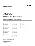
Using the OnBoard-Programming Mode: An initial program has to be programmed into the device
via a programming-tool like the FLASH-Master. It can be connected to an interface on an application-target board. This program is either the full code to be programmed, or should include a so
called BOOT-LOADER located in the lower FLASH-memory-area. The main task of this BOOTLOADER is to start basic software-functions after leaving the RESET-mode and to support the
Flash-Self-Programming-functionality for reprogramming from a connected network.
Figure 1-1: Hardware-environment of Flash-Master
•
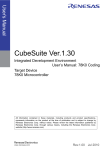
Using the Self-Programming Mode: In self-programming mode data can be programmed to the
flash. Data can be parameters or program code that got into the device by support of the user program. Therefore the user program can use all device specific peripherals like CAN, UART and timers. Once the data is in the device, e.g. buffered in the RAM area, it can be programmed via an
internal programming interface to the upper half flash area. The flash-ROM is divided into two
blocks, an upper (block 1) and a lower block (block 0). Only the upper block can be programmed in
self-programming mode.To write data also into the lower block, the two blocks can be switched with
the swap self-programming function, so that the old lower block will be permanently the upper block.
This new constellation is also valid after RESET. A further call of the swap routine will fail, until the
present upper block is erased.
Figure 1-2: Layout with Self-Programming
CAN
Timer
I/O
User Cod
Programming
Interface
Flash
Programming
10
Vpp Voltage
Generator
Preliminary User’s Manual U14879EE1V0UM00
11
Chapter 1
Introduction
This document explains how self-programming is working and how it can be used under assistance of
an API (Application Programming Interface). This API is realized as a library, written in a higher-level
programming language (ANSI-C). It should facilitate the use of the self-programming functions out of
the user program.
In the second chapter the environment is described how this API can be used in programs to get full
self-programming functionality.
This document is based on the device 78F0828B but can easily be used for other devices with the
same self-programming technology and real time support.
1.2 Self-Programming on µPD78F0828B
The following chapter will describe the main-topics of Self-Programming on the µPD78F0828B and how
the programming is done on the chip.
1.2.1 Description
Starting with a un-programmed chip, the user is responsible to program a boot-loader, supporting the
Self-Programming-functions, in the lower block of the Flash-Area. The Self-Programming support- functions must be included in the final application program, too, if data- or parameter-updates are further
necessary.
By a user-defined communication-channel data must be written to a specified RAM-Area; this data is
later-on programmed to the upper-memory-block.
After programming of upper-ROM-block is done, the ROM-blocks are swapped so the actual code
resides in the old ROM-block1. Now, the new ROM-block0 can be programmed, whereby all FlashMemory is Write-accessible.
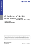
1.2.2 Control of VPP
- Normal Flash-Programming: The user can program the Flash-Area, but no security and no support of RAM-based functions are given while running the Firmware-routines
- Secure Flash Self-Programming: The user can program the Flash-Area, but in case of failures, at
least one ROM-block is recognized to contain valid data.
- RTSF-Selfprogramming: The user can run any function without interrupt, but using watchdog, out
of a pre-defined RAM-Area while using the Self-Programming routines. This is called RealTimeSupportFunction.
Figure 1-3: Outline of Programming-Voltage
12
Preliminary User’s Manual U14879EE1V0UM00
Chapter 1
Introduction
While RESET release different modes can be selected:
- Flash Mode: Connected 10 V to VPP at rising RESET signal will switch to the flash programming
mode. The used serial communication interface is selected by pulsing the VPP voltage. The principle is shown in figure 1-3.
- Normal mode: Ground level is attached to Pin 14; the chip will start user program execution at the
address defined by the RESET vector at address 0000h.
- Self-programming mode: Self-programming mode is called out of the normal mode after 10 V supply to VPP. To achieve a secure programming during all events, like e.g. power fail, the lower flash
block can not be programmed. To program the whole flash, both flash blocks can be exchanged
once. For additional exchanges the upper block has to be erased first.
Real time functions like watch-dog or network communication are also supported during self-programming with the RTSF (Real Time Support Function). RTSF is user code located in RAM and is automatically called within 1ms out of the Self-programming mode.
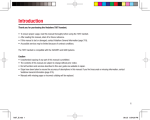
1.2.3 Memory-map in Normal-Mode
In the normal-Mode, the memory-configuration looks like follows:
Figure 1-4: Normal-mode memory-layout
0xFFFF
Special Function Register
256 x 8Bit
0xFF00
General Register
32 x 8Bit
Internal high-speed RAM
1024 x 8Bi
0xFB00
0xFAFF
NOT Useable
0xFA80
0xFA7F
0xFA64
0xFA63
LC-Display RAM
28 x 4Bit
NOT Useable
0xF7DF
Application and DCAN-RAM
0xF600
0xF5FF
0xF000
0xEE00
0xEDFF
0x76F
0x0000
User-Area, Expans. RA
1.5 kByte
Not useable
Internal Flash ROM
Block 1
Internal Flash ROM
Block 0
As described, the ROM is divided into an upper and a lower block; only the upper block is directly
accessible for the Self-Programming routines. Nevertheless, the whole Flash-Area is programmable by
using the Self-Programming Swap-Function.
Preliminary User’s Manual U14879EE1V0UM00
13
Chapter 1
Introduction
1.2.4 Entering Self-Programming Mode
After applying the 10 V to V PP and entering Self-Programming mode, the upper ROM-block will be
switched with the hidden-ROM-Area.
Figure 1-5: Memory-configuration after entering SelfProgramming-Mode
Normal Mode
Self-programming Mode
Internal RAM inkl.
SFR: 1,0Kbytes
Internal RAM inkl.
SFR: 1,0Kbytes
F600
CAN RAM: 0,5 Kb
F600
CAN RAM: 0,5 Kb
Subroutine call
Code executable
RAM: 1,5Kbytes
Code executable
RAM: 1,5Kbytes
F000
F000
EDFF
EDFF
Upper Block
Flash Memory
29,75K bytes
(erasable area)
FLSPM0 <- 1
Hidden ROM
7700
entering
Self-prog. Mode
leaving 7700
Erase
Flash Memory Write
29,75K bytes Verify
(erasable area)
Hidden ROM
FLSPM0 <- 0
Flash Memory
29,75K bytes
Flash Memory
29,75K bytes
Boot Strap
Boot Strap
Interrupt
Subroutine call
Interrupt
Lower Block
From this Hidden-ROM-area, all Self-Programming-functions calls are executed. After the boot-strap
and the code is written, the upper ROM-block contains the new program, so the ROM-blocks are reswitched to enable the new code. Now the new block1 can be programmed. The below figure shows
this in detail.
Figure 1-6: Detailed description of Flash-Programming
F600
Internal RAM inkl.
SFR: 1,0Kbytes
Internal RAM inkl.
SFR: 1,0Kbytes
Internal RAM inkl.
SFR: 1,0Kbytes
Internal RAM inkl.
SFR: 1,0Kbytes
CAN RAM: 0,5 Kb
CAN RAM: 0,5 Kb
CAN RAM: 0,5 Kb
CAN RAM: 0,5 Kb
Code executable
RAM: 1,5Kbytes
Code executable
RAM: 1,5Kbytes
Code executable
RAM: 1,5Kbytes
Code executable
RAM: 1,5Kbytes
Flash Memory
29,75K bytes
(erasable area)
Flash Memory
29,75K bytes
Flash Memory
29,75K bytes
(erasable area)
F000
Flash Memory
29,75K bytes
Boot Strap
Boot Strap
Interrupt
Interrupt
Block 1
Block 0
Block 0
14
Flash Memory
29,75K bytes
Copy / Modify
Boot Strap
Boot Strap
7700
Block 0
Boot Strap
Boot Strap
Flash Memory
29,75K bytes
(erasable area)
Flash Memory
29,75K bytes
Block 1
Block 0
Flash Memory
29,75K bytes
(erasable area)
Block 1
Block 1
EDFF
Boot Strap
Boot Strap
Interrupt
Interrupt
Preliminary User’s Manual U14879EE1V0UM00
Chapter 1
Introduction
1.2.5 The Entry-RAM
The Entry-RAM-Area is a pre-defined area with a length of 32 bytes. These bytes contain all data necessary for the firmware-routines and are initialized by the library-call-function SP_Init.
Normally, pre-defined values are stored here by the Init-Function, so the user shouldn’t change them. If
there is a need to change this values, please follow the information provided in this chapter.
Following picture shows the structure of the EntryRAM-Area.
struct ERAM
{
unsigned char _Reserved1;
unsigned char _Reserved2;
unsigned int _FlashMemStartAdr;
unsigned int _Reserved3;
unsigned char _ByteInFlash_BlockNo;
unsigned char _WriteTimeData1;
unsigned char _EraseTimeData1;
unsigned char _EraseTimeData2;
unsigned char _EraseTimeData3;
unsigned char _ConvTimeData1;
unsigned char _ConvTimeData2;
unsigned char _ConvTimeData3;
unsigned int _WrDatStorStartAdr;
unsigned int _RAMRoutStartAdr;
unsigned int _FlashSwapRetAdr;
unsigned char _IntervTimeData1;
unsigned char _Reserved4[11];
};
The start-address of the entry-RAM-Area is defined in the API-header file and respective the linker-file.
The important elements in the Entry-RAM are described as follows:
•
FlashMemory Start-Address: Here the address takes place, where the Flash-Writing routine starts to
write
•
No. of bytes written in flash-memory: This value has to been set to 0x01allways - description of the
ROM-block number where firmware-routines take effect; only the Write-function is here in use of the
number of bytes which will be written (Maximum of 256 bytes in a row).
•
WriteTimeData1: This value is following the formula:
WriteTime = ( WriteTimeData1 × 2 ) ⁄ ( OperatingFrequency )
The time the ROM-cells are written is declared in this cell.
Example for frequency of 8 MHz:
Operating frequency
8 MHz
•
WriteTimeData1(dec.)
200
Write-Time
50 µsec.
EraseTimeData(1-3): These three values are calculated by the assumption, that in a first try, the
erasing of ROM should take 2 seconds of time; if the first erase wasn’t successful, the erase-time
will be changed to a value about 0.25 seconds and the block will be erased with this time-quanta
again, until the whole ROM is erased.
Preliminary User’s Manual U14879EE1V0UM00
15
Chapter 1
Introduction
For two seconds erasing, the three values are defined as 0xF5, 0xB, 0x5 at 8 MHz following the formula
( EraseTimeData2 + EraseTimeData3 )
-----------------------------------------------------------------------------------------------------------------OperatingFrequency
EraseTime = EraseTimeData1 × 2
The values for TimeData2 and TimeData3 should be left as they are.
Example for Erase-Times of 2 and 0.25 seconds@8 MHz:
OP-Freq.
8 MHz
•
EraseTimeD1 (dec.)
245
244
EraseTimeD2 (dec.)
11
8
EraseTimeD3 (dec.)
5
5
Erase-Time
2.007 sec.
0.250 sec.
ConvTimeData(1-3): The ConversionTimeData defines a value in milliseconds, how long a Flashcell has to be re-written after an over-Erase has occured.This time the over-erased cells are writtenback. A normal time quanta for this matter is about 10ms. This is created by ConvTimeData2 =
0x08, ConvTimeData3 = 0x03 or 0x01 and for 8MHz with ConvTimeData1 = 0x9D following the
equation
ConversionTime = ConvTimeData1 × 2
ConvTimedata2 + ConvTimeData3
--------------------------------------------------------------------------------------------------------OperatingFrequency
The conversion-Time results in 10 msec.
Example for Conversion-Times of 50 and 10 msec with OP-frequency of 8 MHz:
OP-Freq.
8 MHz
ConvTimeD1 (dec.)
195
157
ConvTimeD2 (dec.)
8
8
ConvTimeD3 (dec.)
3
1
Conv.-Time
50 msec.
10.05 msec
•
WriteData StoragBuffer StartAddress: These two bytes define the starting-address, of a RAM
buffer. The RAM buffer is used to stocks data for writing into the upper Flash-block and for verifying.
•
RAM-routine StartAddress: These two bytes contain the address where the user-program is
located. It is called while the RTSF-function in ROM-programming is enabled.
•
FlashSwap ReturnAddress: These cells contain the address, where after the FlashSwap the new
start-Vector of the new program-area is located.
•
ReturnInterval TimeData1: This value adjusts the interval the RTSF-support function is called
depending on the external connected frequency. The ReturnIntervalTime is calculated by the formula:
ReturnIntervalTime = ( ReturnIntervalTimeData1 × 2 ) ⁄ ( OperatingFrequency )
Example for 512 µsec that secures a RTSF-call of less than 1.024 msec.
Return-Interval Time:
OP-Frequency
8 MHz
16
ReturnIntTime Data1 (dec.)
16
Return Interval-Time
0.512 msec.
Preliminary User’s Manual U14879EE1V0UM00
Chapter 1
Introduction
To write this data by user-program, a pointer has to be defined (e.g. pointer_ERAM), which will be
anchored to an array located at the pre-defined EntryRAM-address (e.g. array_ERAM).
If the erase-time values from the first try to the repeated try should be changed, following syntax will do
this for example:
pointer_ERAM = &array_ERAM;
( ... )
pointer_ERAM ->_EraseTimeData1 = RepeEraseTimeData1; // sets the erase-time to shorter
cycle to prevent
pointer_ERAM ->_EraseTimeData2 = RepeEraseTimeData2; // flash-cells from stressing!
pointer_ERAM ->_EraseTimeData3 = RepeEraseTimeData3;
The pointer is linked to the array-structure, then the needed ER-values are set.
Following drawing will show sample values for the single function-times. These values are still preliminary and are intended to be changed. Besides, these values will give intentions for typical times,
changes to upper- or lower-bonds will be possible.
Figure 1-7: Sample time-slices for SP-Routines
The functions used in the Flash-Self-Programming-library to interface the Self-Programming firmware
are shown below.
Preliminary User’s Manual U14879EE1V0UM00
17
Chapter 1
Introduction
1.2.6 Functions in the Self-Programming library
This five functions provide all features to do a Secure Self-Programming of the complete Flash-Area.
Figure 1-8: Functions of Self-Programming
U se r S o ftw a re
SP_Init
SP_
Write
SP_Erase
SP_
SP_
Area
Swap
Verify
S e lf -p r o g r a m m in g F ir m w a r e
Their functionality will be described later on in this user-manual.
1.2.7 Secure Self-Programming
To guarantee secure Flash Self-Programming, independent from e.g. loss of programming-voltage or
loss of device voltage during programming or during switch of the upper- and the lower mem-block, a
special function is designed to get at least one memory-block active after RESET.
Figure 1-9: RESET-execution and boot-signature-recognition
Internal RAM inkl.
SFR: 1,0Kbytes
F600
CAN RAM: 0,5 Kb
Internal RAM inkl.
SFR: 1,0Kbytes
F600
Code executable
RAM: 1,5Kbytes
F000
CAN RAM: 0,5 Kb
Flash Exchang
Mode
RESET
Mode
Code executable
RAM: 1,5Kbytes
F000
EEFF
Signature
Destroy
Signature
EDFF
Flash Memory
30,00K bytes
(erasable area)
Flash Memory
29,75K bytes
(erasable area)
Boot Strap
7800
7700
Signature
7700
Flash Memory
29,75K bytes
Flash Memory
30,00K bytes
Boot Strap
Boot Strap
Interrupt
Hidden
ROM
Write
Signature
Read
Signature
Select Boot Block
Interrupt
Boot
ROM
RESE
18
Preliminary User’s Manual U14879EE1V0UM00
Chapter 1
Introduction
A signature is located on the upper-side of each Flash-block. This signature is written active or nonactive, depending on the status the block should have.
The block with the written signature is automatically the lower block. In unfavourable circumstances
e.g. voltage drop, the signature of the upper Flash-block might be written and the one of the lower block
might not be destroyed.
After RESET, randomly one of the two blocks may be recognized as valid. In this case, the user must
prepare his software to recognize whether the original or the new programmed block is containing the
actual code
1.2.8 RTSF-Support
The RTSF (so called RealTimeSupportFunction)-support gives the user the possibility to let real time
functions like watchdog timer, network management communications or other run while the Self-Programming functions are in use.
To start the RTSF-support by calling the Self-Programming-library-functions, a RTSF-value unequal to
0x0000, equivalent to the start-address of the RTSF-user-function in RAM must be set. This will call the
RTSF-function which will set this start-address of the RTSF-user-support-function into the Entry-RAMArea. For RTSF-usage, a dedicated Area form 0xF000 to max. 0xF5FF in RAM is reserved. The user
must define this Area in his.xcl-link-file and has to copy the RTSF-user-function into RAM by himself.
While calling the Self-Programming-routines, in non-equidistant steps lower than 1msec. the supportfunction is called without halting the Self-Programming-routines.
Figure 1-10: Outline of RealTimeSupportFunction
Internal R AM inkl.
SFR : 1,0Kbytes
F600
C AN R AM : 0,5 Kb
Call User R outine
C ode executable
R AM : 1,5Kbytes
Return
F000
ED FF
Erase
Flash M em ory W rite
29,75K bytes Verify
(erasable area)
Enter
SP-M ode
FLSPM 0<- 1
SW
Loop
<1m s
Hidden
ROM
7700
Flash M em ory
29,75K bytes
STO P
Boot Strap
Interrupt
Nevertheless, it is not dangerous to call user-support-functions probably running longer than the execution-interval of the Self-Programming-function. The SP-function is stopped after the execution-interval
is ended without any respect to the RTSF-user-function-duration.
Using this feature, no long-durating user-RTSF-support-function can disturb the running SP-procedures.
The user-function resides in the Area from 0xF000 to max. 0xF5FF, equivalent to 1.5 KByte of RAM.
This Area must be allocated by the user for RTSF-support.
Preliminary User’s Manual U14879EE1V0UM00
19
Chapter 1
Introduction
As a general overview, the whole procedure of Self-Programming is shown in the following diagram;
please use this as template for all Self-Programming purposes!
Figure 1-11: Complete Self-Programming procedure
Start
Startofof
Self
Programming
Self Programming
RTSF
Call Firmware Subroutine
Copy Code to RAM
(only if RTSF used)
<1ms
Hidden ROM
RTSF
- Erase/Blank check
/Write/Verify
Branch to lower
flash block / RAM
Disable Vpp Voltage
Disable Interrupts
N
Vpp = 0V?
Select Self Programming Mode
RTSF
Y
Enable Vpp Voltage
Prepare Parameters
Select Normal Operating Mode
:User program
Application Program
:User program
(Boot area)
N
Vpp = 10V?
Y
20
End of self
programming
:User Program
(RTSF)
:Hidden ROM
Preliminary User’s Manual U14879EE1V0UM00
Chapter 2
Software
2.1 Memory-demands
2.1.1 Setup the RAM-mapping
As described before in this document, the RAM-usage has to be canalized for using all features of the
Flash-SelfProgramming routines. Some constant memory-layouts are necessary as follows:
An area with a length of 32 Bytes, containing the EntryRAM
The Write Data Storage-Buffer with a defined length of 256 Bytes
The Stack Area, length approximately 40 Byte
The User-Code Area with a max. length of 1.5 KByte, defined from 0xF000 to max. 0xF5FF.
2.1.2 Linker-configuration
In the IAR-workbench the linker-file (xy.xcl) defines the needed areas.
A sample linker-file configuration is shown below:
Figure 2-1: Sample-header-file with mem-configuration
//------------------------------------------------------------------------------------------//
-LINK.XCL//
//
XLINK command file to be used with the 78000 Embedded Workbench
//
using procesor option -v1 memory model option -ms or -mS
//
//-------------------------------------------------------------------------------------------//
Archived: $Revision: 1.1 $
//
(c) Copyright IAR Systems 199
//-------------------------------------------------------------------------------------------//-------------------------------------------------------------------------------------------// changes for Secure SelfProgramming
// (C) NEC Electronics (Germany) GmbH 2000
//--------------------------------------------------------------------------------------------
//-------------------------------------------------------------------------------------------//
Define CPU.
//--------------------------------------------------------------------------------------------c78000
//-------------------------------------------------------------------------------------------//
Define all user-specific RAM-areas for Secure SelfProgrammin
//--------------------------------------------------------------------------------------------Z(DATA)ucode=F000-F5FF
-Z(DATA)MySegER=FE21-FE43
-Z(DATA)MySegRB=F6E0-F7DF
// Area to write user-code in RAM
// RAM-segment for Entry-RAM (32byte)
// RAM-Buffer Segment (here 256Byte)
// ! reduces the DCAN t
// ! 12 Receive-Buffers
The user-code area is fixed to location F000 tomax. F5FF, the Entry-RAM-Area is defined from FE21 to
FE43, resulting in a length of 32 bytes, the Read-Buffer is defined from F6E0 to F7DF, resulting in a
length of 256 Byte.
Preliminary User’s Manual U14879EE1V0UM00
21
Chapter 2
Software
2.1.3 Resulting memory-layout
By allocating the needed segments above, the following Self-Programming memory-layout is generated:
Figure 2-2: Memory-outline using SP-settings
0xFFFF
Special Function Register
256 x 8Bit
0xFF00
General Register
32 x 8Bit
Entry-RAM
Area
0xFB00
0xFAFF
Internal high-speed RAM
1024 x 8Bit
NOT Useable
0xFA80
0xFA7F
0xFA64
0xFA63
0xF7DF
0xF600
0xF5FF
0xF000
0xEDFF
0x76FF
0x0000
LC-Display RAM
28 x 4Bit
NOT Useable
Read Buffer Storage Data
User-Area, Expans. RAM
1.5 kByte
Internal Flash ROM
Block 1
Internal Flash ROM
Block 0
2.2 Prepare Self-Programming
This chapter will describe the conditions to get a full running system with Self-Programming.
2.2.1 Pre-conditions
To get the Software running, the following should be defined before starting programming.
Is there need of a User-function, that provides the ability of Real-Time Support?
If this function is needed, define the approximate length of the program that will reside in the memoryArea from 0xF000 to 0xF5FF.
Which protocol should responsible to get the data to program from outside into the chip?
Define the protocol, using e.g. UART, CSI, CAN.
Where should the incoming data be stored?
Make sure, that there is at least one RAM-area defined with a maximum length of 256 bytes, where the
incoming data can be stored, until it will be written by library-calls into the Flash, so that new data can
be acquired.
Where should the Entry-RAM-Area reside?
Make sure that an Area in RAM with a length of 32 bytes is reserved, so the data necessary for the
Self-Programming-mechanism can be stored.
22
Preliminary User’s Manual U14879EE1V0UM00
Chapter 2
Software
2.3 Application Programming Interface Functions
2.3.1 Standardized Input- and Output-parameters
All functions will use very similar In- and Out-Parameters, which will be described as follows.
Input-Parameters
• RTSF-Parameter
The input-parameter used in every function is the _RTSF-variable.
If this variable is set to 0x0000 while calling the depending SP-library-function, no user-RTSFfunction will be called while making the SelfProgramming-function.
Otherwise, if there is need of the RTSF-Function, the starting-address of this user-function has to be
defined in the function-call; usually, this will define address in the range from 0xF000 to max. 0xF5FF
• SPWriteStartAddress
This variable is used by the Write-function and defines the target-address in the upper Flash-ROMblock, where writing data from the RAM-buffer is started; any value from 0x7800 onwards to 0xEE00
minus SPNoByte is valid.
• SPNoByte
For the Write-Function, this value defines the number of bytes to be written into the Flash-Memory
starting from SPWriteStartAdr onwards. Valid values are from 1 to 256.
• SPBuffStartAddress
Defines the Start-address of the RAM-buffer. This RAM-buffer contains the data for the write-routine
and is used by the Area_Verify-routine, too.
• SwapRetAdr
This address defines the starting-address of the new program, which will be called after the upper and
the lower block were swapped; please remember that this must not be the address the microcontroller
jumps to after executing the RESET-procedure.
While the Swap is executed, the signature of the upper block is written and the signature of the lower
block is destroyed, so that after a RESET-Function is released, the old upper-block retains his new
lower-position and the new program is executed by taking the new start-vector at address 0000.
Preliminary User’s Manual U14879EE1V0UM00
23
Chapter 2
Software
Output-Parameter
Error-Flag
All functions will return the same parameter, but with different values. The different values are worked
within the SP-library, but errors, which are not re-workable will be directed to the calling program. The
error-codes are listed in the following:
Figure 2-3: Return-Error-Messages
Following, a short description of the error-messages follows:
•
Parameter-Error: This error is defined, if some of the values, defined in the Entry-RAM-Area, are not
compatible to the function-execution, e.g. Block-No != 1 or write 20 Bytes to 0xEDF0.
•
Verify-Error: This error is defined when internal verification of written data is not executed correctly.
•
Write-Error: If the data from RAM to Flash-ROM cannot be written correctly, this error will be shown.
•
OverErase-Error: This error is returned if any cell is overerased. This could happen in following
cases:
- erasing takes too long
- erased cells are erased again
- cells, programmed with FF, (equals to never programmed), are erased.
The last two cases can be avoided by using the prewrite-function before each erase-function call.
Depending of the over-erase status of the cell, an over-erase error could be corrected by using the
WriteBack-function.
•
BlankCheck-Error: If the internal Blank-Check finds non-blank memory-cells, this error-code is generated.
•
No error: No error is encountered.
24
Preliminary User’s Manual U14879EE1V0UM00
Chapter 2
Software
2.3.2 SP_Init
Figure 2-4: Header of Function SP_Init
Like described in the above picture, the In- and Out-Parameters are as follows:
Input-parameters:
output-parameters:
_RTSF_Adr: 0x0000 when no RTSF-support is needed
RB3_B: error-code stored in register B of Bank 3
The function calls several firmware-routines to initialise and check the EntryRAM. If a RealTimeSupportFunction is requested by the input-parameter, the RTSF-function is automatically called within the
used firmware-routines.
Default values out of the Firmware-ROM, that are based on an 8MHz clock are written into the EntryRAM-Area. These are 50 µsec, 2 sec and 10 msec for the three parameters write-, erase- and conversion-time.
After setting these values and testing if the settings are in a defined range, a return-value is created and
the function is ended.
If the values written by the SP_Init-function doesn’t fit into users need, they must be rewritten manually.
With the given start-address and the offset from chapter “The Entry-RAM” o n page7, all recent values
can be changed.
The Start-Address of Entry-RAM must be defined in the.xcl-file, because all library-functions use this
address to get data out of the Entry-RAM and start the Flash-Programming!
The following table shows an example for an Init-routine.
er->_ByteInFlash_BlockNo
er->_WriteTimeData1
er->_EraseTimeData1
er->_EraseTimeData2
er->_EraseTimeData3
er->_ConvTimeData1
er->_ConvTimeData2
er->_ConvTimeData3
= BlockNo;
= WriteTimeData1;
= FirstEraseTimeData1;
= FirstEraseTimeData2;
= FirstEraseTimeData3;
= FirstConvTimeData1;
= FirstConvTimeData2;
= FirstConvTimeData3;
// init BlNo / No of Byte in Flash
// init Time to write Data
// init Erase Time Data in three
// vars
// init conversion Time data in
// three vars
This can be done, if the standardized values, written into the Entry-RAM by the library-Initilization, don’t
fit into the users special needs.
Preliminary User’s Manual U14879EE1V0UM00
25
Chapter 2
Software
2.3.3 SP_Erase
Figure 2-5: Header-file of Erase-function
The Erase-function is the most complex function of the library-set. The only input-parameter needed is
the RTSF-usage-value.
Input-parameters:
Output-parameters:
_RTSF_Adr: 0x0000 when no RTSF-support is needed
RB3_B: error-code stored in register B of Bank 3
The output-parameter will give information about the status of Flash-block-Erasing. Between the calling
and the ending of the erase-function, several options are calculated in the Erase-function itself. A short
overview should give the user an introduction what the Erase-function will do internal:
First of all, a blank-Check is done to determine, whether the ROM-block to be flashed is already empty
or not.
If the Area is blank, the erase-function is finished with no-error. If there are non-blanked cells, the PreWriting of the area is initiated. This Pre-Writing should preserve the ROM-Area from OverErase-Errors
by writing 0x00 to all cells.
After this Pre-Write is done, the full upper ROM-Area will be erased. To get a fast time for erasing and a
Type of Erasing
Initial Erasing
Repeated Erasing
internal SP-lib. Variable-Name
FirstEraseTimeData(1..3)
RepeEraseTimeData(1..3)
Time-quanta
apr. 2 sec
apr. 0.25 sec
minimum stress for the flash-block the erasing is done in an iterative way. Between each step, an
erase-success is checked by a blank-check.
Type of Erasing
Initial Erasing
Repeated Erasing
Max Erasing
internal SP-lib. Variable-Name
FirstEraseTimeData(1..3)
RepeEraseTimeData(1..3)
-
Time-quanta
apr. 2 sec
apr. 0.25 sec
30 sec
While the first Erase-cycle is not successful, the writing-parameters are changed to the shorter repetitive values to start the next erase-iteration.
26
Preliminary User’s Manual U14879EE1V0UM00
Chapter 2
Software
In case of OverErasing, the SP_Erase-subroutine will write-Back the FlashROM. This means, that the
write-back-function tries to repair the over-erased cell by kind of special writing.
The SP_Erase-function will be ended either by successful Blank-Check or reaching the maximum
erase- or conversion-time. By reaching the maximum times an error-code is returned.
2.3.4 SP_Write
Figure 2-6: API-Header for SP_Write
As described in the above header-file, this function uses more than just the RTSF-input-parameters:
Input-parameters:
SP_WriteStartAddress: Sets address where in
ROM data-writing should be started
SPNoByte: Defines the number of Bytes to write
in ROM
SPBuffStartAdr: Declares the start-address
where data in RAM resides
_RTSF_Adr: 0x0000 when no RTSF-support is
needed
output-parameters:
RB3_B: error-code stored in register B of Bank 3
Write-error: Writing to at least one bit was not successful.
Parameter Error: WriteStartAdr + SPNoByte exceeds writeable Flash-Area
The SP_Write-function fetches data from pre-defined RAM-area and writes it into the upper Flash-Block
at starting address, defined while the function is called.
If the RTSF-support is requested, the start-address of the RTSF-support-function is written to the
according Entry-RAM-Bytes.
With the input-parameters, the EntryRAM-values Flash Memory Start-Address, No. of bytes written in
flash-memory and WriteData_StoragBuffer_StartAddress are declared.
The write-Time, used for the write-in of data, is calculated as described in the following formula:
WriteTime = ( WriteTimeData1 × 2 ) ⁄ ( OperatingFrequency )
With an operating-Frequency of 8 MHz and a Data1 of 200, the basic WriteTime will amount to 50 µsec.
Preliminary User’s Manual U14879EE1V0UM00
27
Chapter 2
Software
2.3.5 SP_AreaVerify
Figure 2-7: API-header for the SP_AreaVerify-Function
The Verify-function needs also more than one calling-parameter. The ROM-address, where the tempdata will be written to, is still defined.
The parameters are listed in the following table:
Input-parameters:
SP_BuffStartAdr: Sets address of RAM-buffer
where temporarily data is stored
_RTSF_Adr: 0x0000 when no RTSF-support is
needed
output-parameters:
RB3_B: error-code stored in register B of Bank 3
The verification of the whole Flash-Area is done by this function. The input-parameter SP_BuffStartAdr
is copied into EntryRAM-Area to the WriteDataStorageStartAdr.
The firmware-routine does a byte-to-byte-compare of the whole Flash-block in 256-Byte-steps. Therefore, the RAM-buffer is used to copy the data out of the Flash into the RAM and do the comparison. If
the check wasn’t successful, an error is generated and the test is ended.
Please take care, that the writing of the data and the AreaVerify shouldn’t go apart to long. A successful
test will guarantee a data-security of 10 years.
28
Preliminary User’s Manual U14879EE1V0UM00
Chapter 2
Software
2.3.6 SP_Swap
Figure 2-8: Header-file of SP_Swap-function
The Swap-function should be called after all needed data is written from RAM to Flash, so a full-featured program is located in the upper memory-block. This following, the upper- and the lower block must
be switched, so the former lower-block can be erased and written to access the whole Flash-ROMArea.
Input-parameters:
output-parameters:
SwapRetAdr: Sets address where program coun- RB3_B: error-code stored in register B of Bank 3
ter after swap has to point to
_RTSF_Adr: 0x0000 when no RTSF-support is
needed
If the Swap is executed, the program counter is set to the SwapReturnAddress at leaving the firmwareroutine. The starting-address of the related program should be located here.
In case of error while executing the Swap-function (e.g. losing the VPP), following figure declares, which
ROM-block will actual be the upper ROM-block:
Figure 2-9: Different effects of Swap-routine
Swap-function execution
Swap withou
any erro
old upper Flash-block
is new code-Flash-block
Error before
changing
the signature
old block
=
new block
Preliminary User’s Manual U14879EE1V0UM00
Error occurs whil
executing Swaperror between
routine
setting new signature and destroing old one
p h y s . b lo c k
1 w ill b e
b o o t - b lo c k
29
[MEMO]
30
Preliminary User’s Manual U14879EE1V0UM00
Appendix
A Example-programming-sequence
To guide the user by programming the Flash-Device with the on-chip Secure Self-Programming, a sample programming-sequence is shown.
First of all, the linker-file should be configured to specify the used RAM and Flash-Areas.
Figure A-1: Example for Linker-file in IAR-workbench
//------------------------------------------------------------------------------------------//
-LINK.XCL
//
// XLINK command file to be used with the 78000 Embedded Workbenc
// using procesor option -v1 memory model option -ms or -mS.
//
//------------------------------------------------------------------------------------------// Archived: $Revision: 1.1 $
//
(c) Copyright IAR Systems 1997
//------------------------------------------------------------------------------------------//------------------------------------------------------------------------------------------// changes for Secure SelfProgramming
// (C) NEC Electronics (Germany) GmbH 2000
//-------------------------------------------------------------------------------------------
//------------------------------------------------------------------------------------------// Define CPU.
//-------------------------------------------------------------------------------------------c78000
//------------------------------------------------------------------------------------------// Define all user-specific RAM-areas for Secure SelfProgramming
//-------------------------------------------------------------------------------------------Z(DATA)ucode=F000-F5FF
-Z(DATA)MySegER=FE21-FE43
-Z(DATA)MySegRB=F6E0-F7DF
// Area to write user-code in RAM
// RAM-segment for Entry-RAM (32byte)
// RAM-Buffer Segment (here 256Byte)
//------------------------------------------------------------------------------------------//
Define all other Self-Programming related stuff
//-------------------------------------------------------------------------------------------Z(CODE)USERCODE=4000-45FF
-Z(CODE)SWAPCODE=4600-4BFF
// Area where user-code in ROM resides
// Area where Code for Swap resides
The used linker-file defines following Areas:
•
Ucode: Area, where the User-code used for the RTSF-support-function will reside. Not only in this
example, this Area should be from 0xF000 to max. 0xF5FF.
•
MySegER: Area which includes the Entry-RAM-Area; the example defines this from 0xFE21 to
0xFE43
•
MySegRB: This Area resides in RAM and stores the data read by a protocol like CAN. The example
sets this value from 0xF6E0 to 0xF7DF.
•
USERCODE: By first programming, this area contains the data that will be copied as RTSF-usersupport function into the Ucode-Area.
•
SWAPCODE: This area contains code which can be copied to the Flash and be called after both
Flash-blocks have been swapped.
To complete the example, the non-library-version of the MAIN.c-file is given; here certain values are
defined for the CAN-ASSP3, which should be carried by the user to guarantee Self-Programming-functionality:
Preliminary User’s Manual U14879EE1V0UM00
31
Figure A-2: Example for Self-Programming MAIN.c-file
The SP_lib.h file is part of the library, the SP_API.h-file is delivered with the library; herein are defined
values which can be changed to fit into users needs.
The used registers should be set in a way like shown above to provide the user with the needed RAM,
Flash and system frequency.
Following this, the Self-Programming functions are called in the described way. Please note, that there
are only 128 bytes copied for this example; that wouldn’t be enough to support further Self-Programming-functions!
32
Preliminary User’s Manual U14879EE1V0UM00
In short terms, the following sequence must be applied:
•
Define used system-RAM- and -Flash-Areas
•
Use SP_Init to initialize the Entry-RAM-Area with valid values
•
Use SP_Erase to erase the upper Flash-Memory-block
•
Be sure that the data to be programmed in the formerly blanked Flash-block is located in the RAMBuffer
•
Call SP_Write to write the data from RAM to Flash
•
Get the Verification of the written data with SP_Verify
•
Do a Swap using SP_Swap to activate the new written program
•
Program the now new upper-block with data from RAM-Buffer with steps described above.
As description, the following flowchart gives an overview how to program the Flash-ROM:
Preliminary User’s Manual U14879EE1V0UM00
33
Figure A-3: Sample-Flowchart for complete SP-description
After the declaration is done, the user-program should define a protocol which can carry the data into
the MySegRB-Area in blocks of 256 Byte.
When the area is filled, the Self-Programming mode has to be entered by calling the belonging SP-Routines.
First, the steps A to E in the above given Flowchart are executed to get a fully programmed upper
Flash-memory-block. With swapping both blocks, the new upper-block can be programmed.
Please remember, that a boot loader, containing the library for Self-Programming, has to be
included in the new-programmed application for future Self-Programming.
34
Preliminary User’s Manual U14879EE1V0UM00
Appendix
B Programming with FLASH-MASTER
The following sequence shows the monitor of the flash-master, connected to a PCvia any Terminal-program:
Figure B-1: Output-sequence of Flash-Master-Software
To run the above shown Flash-Master-sequence, a hex-formatted-file must be generated.
Preliminary User’s Manual U14879EE1V0UM00
35
This hexfile is downloaded into the Flash-Master.
Figure B-2: Download of intel-hex-formatted file into the Flash-Master
Than the combined sequence BlankCheck - PreWrite - Erase - (WriteBack) is executed.
After this is finished, a system-RESET has to be done to activate the formerly written program.
36
Preliminary User’s Manual U14879EE1V0UM00
The settings for the device are shown in the last picture:
Figure B-3: Device-Properties
Using this sequence, the device can be programmed with the Flash-Master as easy as with the OnChip Secure Self-Programming-functions.
Preliminary User’s Manual U14879EE1V0UM00
37
[MEMO]
38
Preliminary User’s Manual U14879EE1V0UM00
Appendix C
•
Documentation
Version
V 1.0
•
Revision History
Description
Initial Documentation
Self-Programming Library
Version
V 1.0
Description
Initial Library-release
Preliminary User’s Manual U14879EE1V0UM00
39
[MEMO]
40
Preliminary User’s Manual U14879EE1V0UM00
Appendix D
Related Software
To use the described SelfProgramming-features, the following Software-parts are necessary:
Description
Header-file with API-Information
library-file with described library-functions to use with 78F0828b
Emulation-library
Device-file for 78F0828b
Sample Link-file for use with the IAR-workbench
library with outsourced standard-library-calls
Name
SP_API.h
SP_lib.r26
emulator.r26
Df0828b.h
SP_Lnk.xc
SP_l06fit
Preliminary User’s Manual U14879EE1V0UM00
41
[MEMO]
42
Preliminary User’s Manual U14879EE1V0UM00
Facsimile Message
From:
Name
Company
Tel.
Although NEC has taken all possible steps
to ensure that the documentation supplied
to our customers is complete, bug free
and up-to-date, we readily accept that
errors may occur. Despite all the care and
precautions we've taken, you may
encounter problems in the documentation.
Please complete this form whenever
you'd like to report errors or suggest
improvements to us.
FAX
Address
Thank you for your kind support.
North America
Hong Kong, Philippines, Oceania
NEC Electronics Inc.
NEC Electronics Hong Kong Ltd.
Corporate Communications Dept. Fax: +852-2886-9022/9044
Fax: 1-800-729-9288
1-408-588-6130
Korea
Europe
NEC Electronics Hong Kong Ltd.
NEC Electronics (Europe) GmbH
Seoul Branch
Technical Documentation Dept.
Fax: 02-528-4411
Fax: +49-211-6503-274
South America
NEC do Brasil S.A.
Fax: +55-11-6465-6829
Asian Nations except Philippines
NEC Electronics Singapore Pte. Ltd.
Fax: +65-250-3583
Japan
NEC Semiconductor Technical Hotline
Fax: 044-548-7900
Taiwan
NEC Electronics Taiwan Ltd.
Fax: 02-2719-5951
I would like to report the following error/make the following suggestion:
Document title:
Document number:
Page number:
If possible, please fax the referenced page or drawing.
Document Rating
Excellent
Good
Acceptable
Poor
Clarity
Technical Accuracy
Organization
CS 99.1