1
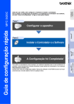
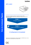
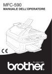
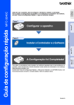
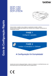
MCAC-2012-36
COMMERCIAL AIR CONDITIONERS
Centrifugal Chiller
2012
Commercial Air Conditioner Business Units
Midea Air Conditioning and Refrigeration Sector
Add: West region of Midea commercial air conditioner department, Industry Avenue,
Beijiao, Shunde, Foshan, Guangdong, P.R. China Postal code:528311
Tel: +86-757-22394101 Fax: +86-757-26338003
http://www.midea.com http://www.mideaaircon.com
Corporate
Introduction
Midea Group
From its humble beginnings in 1968, Midea has developed into a
large corporation, covering HVAC, appliances, lighting, industrial
components, logistics, and real estate. Its 40 years of relentless
growth has brought its global turnover to $14 billion USD in 2009.
Consequently, Midea has created over 150,000 jobs both within
China and all over the world. In addition to providing affordable
goods to consumers worldwide, Midea is a responsible corporate
citizen, and has contributed to several social causes.
Midea believes in creating value through rapid response to
market demands, cost-efficient operations and consumer
satisfaction. As a result, Midea wields vast production capacities
to meet these demands, a fully integrated manufacturing
process, and a comprehensive range of affordable, high-quality
products to serve its global customers.
Today, Midea is a home appliance leader in China. The company
continues to actively globalize its operation by opening plants in
Vietnam, Belarus and Egypt. Additionally, Midea has several
forthcoming plants in order to offer enhanced products and
services closer to the market.
Midea CAC (MCAC)
As a key part of Midea Group, the Midea Central Air Conditioner
(CAC) Business Unit is a professional CAC products supplier and
commercial products solution expert. Since 1999 Midea central
air-conditioner contributes to the commercial product R&D and
technology innovation. By cooperating with the international
enterprises plus the independent R&D, Midea CAC achieves big
success in the commercial air-conditioner market and has
established thousands of sample projects all over the world.
Right now Midea CAC is one of the most professional CAC products
supplier as well as the professional project solution provider in
marketing, sales, project design and after service etc.
MCAC Chongqing factory with 14 product lines concentrates on the
water cooled centrifugal / screw/ scroll chillers, Air cooled screw/
scroll chillers, AHU/FCU etc.
MCAC Shunde factory with 31 product lines concentrates on the
VRF (DC inverter product/ Digital scroll product), split product, heat
pump water heater, AHU/FCU etc.
07
Centrifugal Chiller
Centrifugal Chiller
MIDEA CHILLER
MANUFACTURING-BASE
INTRODUCTION
With 46 years experience in chiller industry, Midea Chongqing chiller manufacturing base is becoming
one of the largest chiller company in China. It covers an area of 800 Mu (137 acre), with a registered
capital of 12.5 million US $ and a total investment of over 0.6 billion US$. There are 6 product series
and over 100 model products including centrifugal chiller, screw water chiller, scroll water chiller,
water-cooled packaged unit, and central air-conditioning indoor terminal device(AHU/FCU). Five chiller
manufacturing shops with 14 flexible production lines lead an anual manufacturing capacity of 250
units centrifugal chiller, 1000 units of air cooled screw chiller, 2000 units of water cooled screw chiller
and 200000 units of AHU product.
Strong R&D and manufacturing capacity makes Midea Chongqing general become the fastest
developing company in chiller industry. The chiller test lab which is certified by China National
Refrigeration Equipment Inspection Center is the largest refrigeration test capacity in Asia. The
engineer team with 100 top engineers and 2 chiller experts who were awarded by the central
government in structure, electricity, performance testing and software aspect makes Midea the
headship in chiller industry. In the year of 2011 Midea refrigeration group invests another 150 million
RMB for test lab as ARI test floor, big capacity air cooled screw life span testing room, 1500kW
compressor motor test floor, etc.
Concentrating on energy-saving and ejection-decreasing, Midea Chongqing chiller factory commits
itself to the reliable and high efficiency products for the world. The chiller products are widely used in
different countries and obtain good public praise from the clients. The solutions for the Beijing capital
international airport ,Jakarta international airport, China rapid transit station won good feedback and
commendation. Continuing with the past and opening up the future, Midea chiller brand will go further
and create an illustrious future.
CONTENTS
05
Nomenclature
06
Features and benefits
09
Specification
14
Performance curve
16
Dimension
24
Refrigeration cycle
25
Microprocessor control
30
Typical wiring diagram
35
Mechanical specification
04
05
Centrifugal Chiller
Centrifugal Chiller
FEATURES AND BENEFITS
NOMENCLATURE
LC 1 500
M
S
Near half a century of experience in design and manufacture of the chiller product enable Midea Company
continues deliver products of high quality, high reliability and high efficiency to our customers all over the world.
Midea independent designed second generation “Smart Star” centrifugal chiller use environment friendly R134a
refrigerant which is not subject to scheduled phase out. And it has been proven can achieve high efficiency
without compromising the environment and the effects of direct and indirect global warming potential are
dramatically diminished.
10
Environment Friendly R134a
Power Supply
10-10kV None-380V
Centrifuge series
S- dual stages
None- single stage
Product series code
Cooling capacity,RT
R134a centrifugal chiller
Environment and its sustainability is the responsibility of any company who can
supply excellent products and service to the customers .Midea has long been
committed to the environment and its sustainability, the Midea “Smart Star”
centrifugal chiller provide our customers with a non-ozone depleting R134a
refrigerant that can achieve high-efficiency, Chlorine-free, long-term solution
without subject to refrigerant phase out. At the same time, R-134a chillers
operate with the entire system above atmospheric pressure at all times, no need
purge unit. In the event of a small leakage, refrigerant escapes from the chiller to
the atmosphere, that allows easy detection and repair. And R134a features
lowest toxicity and flammability rating which translate into lowest hazard.
High Reliability
Single-stage Semi-hermetic positive pressure compressor utilizes advanced international leading NREC design
technology. Single-stage design eliminate the additional moving part in the multi-stage compressor, such as
second impeller, this feature increased the reliability. The refrigerant cooled hermetic motor sealed from the
external air and environment that greatly eliminates the contaminant possibility. Combine with shell-tube type heat
exchangers designed,manufactured and tested according to the national standard of China. These practice
ensure Midea centrifugal chiller achieve high reliability.
Semi-hermetic Motor
The motors are hermetically sealed from the machineroom, cooling is
accomplished by spraying liquid refrigerant on the motor windings and shaft. This
highly efficient cooling method results in the use of smaller, cooler-running
motors. As a result, hermetic motors require lower inrush current and are
smaller,lighter and quieter than comparable air-cooled motors.
Modular Construction
The evaporator, condenser, and compressor assemblies are completely bolted together, making the chillers easy
to disassembly and reassembly at the jobsite. This feature makes the chiller easy for transportation and lessen
access problem in the jobsite. This attribute can mean considerable installation cost savings on many retrofit
applications that may have limited doorway size.
06
07
Centrifugal Chiller
Centrifugal Chiller
High Efficiency Fully-shrouded Impeller
Condenser Baffle
Fully-shrouded impeller features high strength aluminum-alloy
backward curved vanes, refrigerant gas flows through the internal
impeller passages without hydraulic interaction with the stationary
casing walls. The impeller is designed for balanced thrust and is
dynamically balanced and over speed tested.
The baffle prevents direct impingement of high velocity compressor gas onto the condenser tubes. That
eliminates the related vibration and wears of the tubes and distributes the refrigerant flow evenly over the
length of the vessel for improved efficiency.
Keyless Impeller Coupling
The impeller and the main shaft are coupled by keyless connection,
it eliminates stress concentration on the power transmission surface
and thus the life span of the impeller is greatly increased. Since
there is no friction, the efficiency is higher than the traditional key
coupling. This unmatched mechanical design was awarded by the
State Intellectual Property Office of P.R.China. (Patent No.ZL 01 2
56825.2)
Precise Gearing
The specially engineered, single helical gear with crowned teeth
keep more than one tooth in contact at all times to provide even
distribution of compressor load and quiet operation. Gear tooth
surfaces are case hardened and precision ground which can reach
the class of 5. Gears are integrally assembled in the compressor
rotor support and are oil film lubricated. Each gear is individually
mounted in its own journal and thrust bearings to isolate it from
impeller and motor forces. The double layer soundproof compressor
design prevents the gear contacting noise.
Lower Sound Levels and Vibration
Special engineered gearing, double soundproof gearbox structure, optimized impeller and tunnel design
ensure our chiller achieve lower sound levels. A gear-driven compressor runs at higher impeller rotational
speeds but tends to have less vibration than the larger, much heavier, direct drive units.
Advanced Capacity Adjustment
Inlet guide vanes work together with moveable diffuser lead to
stepless capacity range from 10% to 100% and free of surge. This is
why Midea centrifugal chiller can achieve high part load efficiency.
And this technology was awarded by the State Intellectual Property
Office of P.R.China. (Patent No.ZL01 2 56824.4).
Reliable Lubricant System
The lubrication system consists of an internal oil sump with oil
heaters, positive displacement oil pump, brazed plate oil cooler,
and oil return line. High position oil sump supply oil to the gear
surface for lubrication, prevent the gear from burnt if sudden
power loss happens.
External Oil Filter and Oil cooler
A plate type oil cooler is factory mounted aside the compressor.
An external oil filter and oil cooler is easy to do maintenance and
replacement. Change of the oil filter or oil cooler can be done after
closed the isolation valve in the pipe line.
Unmatched Oil Reclaim System
During the running of chiller unit, a small amount of lube may interfuses into the refrigerant. Midea patented
oil reclaim system designed to return the oil from the heat exchanger back to the oil tank. It will improve the
refrigerant purity to increase the thermal exchange efficiency and provide sufficient oil to compressor.
Low Inrush Current
Standard starter for Midea centrifugal chiller is a popular type for centrifugal chiller applications, that’s
wye-delta starter. The motor windings first connect in a “wye” configuration to reduce the inrush current to
33.3% of locked rotor amps and producing 33.3% of normal starting torque. After a brief delay (transition
time), the electrical load is momentarily transitioned to resistances while the motor windings are changed to
the “delta” configuration. The resistances minimize the second inrush current when the delta configuration
becomes active.
100% Factory Run-Tested
In Midea factory, after assembled, the unit will 100% go through performance test in the test center. The
benefits of a performance test include verification of performance, prevention of operational problems and
assurance of a smooth start-up. A chiller that has been tested is operation and performance-proven.
08
09
Centrifugal Chiller
Centrifugal Chiller
SPECIFICATION
Model
LC350M
LC400M
LC450M
LC500M
LC550M
350
400
450
500
550
kW
1230
1406
1582
1758
1934
104kcal/h
105
120
136
151
166
Item
RT
Cooling
capacity
Evaporator
Condenser
Compressor
Weight
Dimension
LC600M
LC650M
Cooling
capacity
RT
600
650
700
750
800
kW
2110
2285
2461
2637
2814
104kcal/h
LC700M
LC750M
LC800M
181
196
211
226
242
Chilled water flow volume
m3/h
210
242
272
302
332
Chilled water flow volume
m3/h
362
392
422
452
484
Chilled water pressure drop
kPa
80
85
82
80
78
Chilled water pressure drop
kPa
82
90
86
92
90
Pass
—
2
Evaporator
Pass
—
2
Fouling factor
m ·°C/kW
0.086
Fouling factor
m ·°C/kW
0.086
Water side design pressure
Mpa
1.0
Water side design pressure
Mpa
1.0
Chilled water inlet/outlet
temperature
°C
12/7
Chilled water inlet/outlet
temperature
°C
12/7
Water pipe inlet/outlet diameter
—
Water pipe inlet/outlet diameter
—
DN250
DN250
DN250
DN250
DN300
3
2
DN200
DN200
DN200
DN200
DN250
2
Cooling water flow volume
3
m /h
256
292
327
362
397
Cooling water flow volume
m /h
433
466
501
537
575
Cooling water pressure drop
kPa
88
88
89
90
85
Cooling water pressure drop
kPa
88
92
93
92
89
Pass
—
2
Pass
—
2
Fouling factor
m2·°C/kW
0.086
Fouling factor
m2 ·°C/kW
0.086
Water side design pressure
Mpa
1.0
Water side design pressure
Mpa
1.0
Cooling water inlet/outlet
temperature
°C
32/37
Cooling water inlet/outlet
temperature
°C
32/37
Water pipe inlet/outlet diameter
—
DN200
DN200
DN200
DN200
DN250
Water pipe inlet/outlet diameter
—
DN250
DN250
DN250
DN250
DN300
Running power
kW
230
262
293
313
345
Running power
kW
376
406
437
470
500
Configured power
kW
300
300
385
385
385
Configured power
kW
445
490
490
560
560
Power supply
V-Ph-Hz
380–3-50
Rated Current(380V)
A
694
741
798
858
913
Starting Current (380V)
Condenser
Power supply
V-Ph-Hz
Rated Current(380V)
A
424
484
541
578
637
Starting Current (380V)
A
1199
1199
1538
1538
1538
A
1778
1947
1947
2225
2225
Rated Current(10000V)
A
\
\
\
\
\
Rated Current(10000V)
A
\
29
31
33
35
Starting Current(10000V)
A
\
\
\
\
\
Starting Current(10000V)
A
\
256
256
292
292
Motor rotate speed
RPM
2960
Motor rotate speed
RPM
Refrigerant
Motor cooled by
380–3-50
Motor cooled by
Efficiency
Model
Item
—
kW/RT
Shipping weight
kg
7205
Running weight
kg
8279
8438
R134a Charge
kg
400
500
Length
mm
4671
Width
mm
1850
Height
mm
2054
0.657
0.655
0.651
0.626
0.627
Compressor
Efficiency
380/6000/10000–3-50
2960
Refrigerant
—
kW/RT
0.627
0.625
0.624
0.627
0.625
7630
8365
Shipping weight
kg
8550
10890
10940
11170
11325
8702
8938
9795
Running weight
kg
10046
12206
12399
12786
13020
500
500
550
R134a Charge
kg
550
660
680
680
740
4671
4671
4671
4725
Length
mm
4725
5077
5077
5077
5077
1850
1850
1850
1990
Width
mm
1990
2200
2200
2200
2300
2054
2054
2054
2162
Height
mm
2162
2540
2540
2540
2540
7325
7510
Weight
Dimension
Notes:
Notes:
1. Nominal Cooling capacities are based on following conditions:
1. Nominal Cooling capacities are based on following conditions:
Chilled water inlet/outlet temperature 12°C/7°C(53.6°F/44.6°F);Cooling water inlet/outlet temperature 32°C/37°C(89.6°F/98.6°F).
Chilled water inlet/outlet temperature 12°C/7°C(53.6°F/44.6°F);Cooling water inlet/outlet temperature 32°C/37°C(89.6°F/98.6°F).
2. The design fouling factor for both evaporator and condenser are 0.086m2 ·°C/kW (0.0005ft2 ·°F·hr/Btu),otherwise can be customized.
2.The design fouling factor for both evaporator and condenser are 0.086m2 ·°C/kW (0.0005ft2 ·°F·hr/Btu),otherwise can be customized.
3. The design working pressure for both evaporator and condenser are 1.0MPa, higher pressure demand can be customized.
3. The design working pressure for both evaporator and condenser are 1.0MPa, higher pressure demand can be customized.
10
11
Centrifugal Chiller
Centrifugal Chiller
Model
LC850M
LC900M
LC950M
LC1000M
LC1100M
RT
850
900
950
1000
1100
kW
2988
3165
3340
3510
3867
Item
Cooling
capacity
Evaporator
Condenser
Compressor
10 kcal/h
4
Dimension
RT
1200
1300
1400
1500
1600
1700
kW
4220
4572
4924
5276
5627
5978
104kcal/h
257
272
287
302
332
363
393
423
454
484
514
m3/h
514
544
574
604
664
Chilled water flow volume
m3/h
726
786
847
907
968
1028
Chilled water pressure drop
kPa
88
92
92
88
92
Chilled water pressure drop
kPa
95
102
115
120
118
120
DN400
DN400
Pass
—
2
Evaporator
Pass
—
2
Fouling factor
m ·℃/kW
0.086
Fouling factor
m ·℃/kW
0.086
Water side design pressure
Mpa
1.0
Water side design pressure
Mpa
1.0
Chilled water inlet/outlet
temperature
℃
12/7
Chilled water inlet/outlet
temperature
℃
12/7
Water pipe inlet/outlet diameter
—
Water pipe inlet/outlet diameter
—
DN300
DN350
3
2
DN300
DN300
DN300
DN300
DN300
2
DN350 DN350
Cooling water flow volume
3
m /h
611
645
680
719
789
Cooling water flow volume
m /h
862
926
992
1063
1135
1204
Cooling water pressure drop
kPa
95
92
88
92
91
Cooling water pressure drop
kPa
96
94
105
108
115
112
Pass
—
2
Pass
—
2
Fouling factor
m2 ·℃/kW
0.086
Fouling factor
m2 ·℃/kW
0.086
Water side design pressure
Mpa
1.0
Water side design pressure
Mpa
1.0
Cooling water inlet/outlet
temperature
℃
32/37
Cooling water inlet/outlet
temperature
℃
32/37
Water pipe inlet/outlet diameter
—
DN300
DN300
DN300
DN300
DN350
Water pipe inlet/outlet diameter
—
DN350
DN350
DN400
DN400
Running power
kW
532
563
595
623
679
Running power
kW
750
815
870
930
990
1050
Configured power
kW
630
630
695
695
760
Configured power
kW
840
840
990
990
1100
1100
Condenser
Power supply
V-Ph-Hz
Rated Current(380V)
A
966
1022
1081
1131
1233
Starting Current (380V)
A
2503
2503
2761
2761
3020
40
42
44
48
329
363
363
378
Motor rotate speed
RPM
380/6000/10000–3-50
A
38
Starting Current(10000V)
A
329
Motor rotate speed
RPM
Power supply
Compressor
2960
Refrigerant
Motor cooled by
Weight
Cooling
capacity
LC1200M LC1300M LC1400M LC1500M LC1600M LC1700M
Chilled water flow volume
Rated Current(10000V)
Efficiency
Model
Item
0.626
0.626
0.626
0.617
kW/RT
Shipping weight
kg
11685
11830
14160
14330
14480
Running weight
kg
13681
13868
16532
16652
16832
R134a Charge
mm
790
790
820
820
900
Length
mm
5077
5077
5160
5160
5160
Width
mm
2300
2300
2500
2500
2500
2540
2540
2625
2625
2625
Height
V-Ph-Hz 380/6000/10000–3-50 6000/10000–3-50 6000/10000–3-50
Efficiency
Weight
Dimension
\
\
A
1362
1456
Starting Current (380V)
A
3337
3337
\
\
\
\
Rated Current(10000V)
A
53
57
61
65
69
72
Starting Current(10000V)
A
418
418
466
466
518
518
2960
Refrigerant
—
kW/RT
0.625
0.627
0.621
0.620
0.619
0.618
Shipping weight
kg
14600
16180
17737
18189
19218
19453
Running weight
kg
17480
18250
20203
20424
22363
23485
R134a Charge
kg
1050
1260
1310
1400
1420
1470
Length
mm
5160
5189
5540
5540
5540
5590
Width
mm
2500
2700
2700
2700
2700
2880
Height
mm
2625
2780
2880
2880
2880
3030
Notes:
Notes:
1. Nominal Cooling capacities are based on following conditions:
1. Nominal Cooling capacities are based on following conditions:
Chilled water inlet/outlet temperature 12°C/7°C(53.6°F/44.6°F);Cooling water inlet/outlet temperature 32°C/37°C(89.6°F/98.6°F).
\
\
Rated Current(380V)
Motor cooled by
0.623
—
DN350 DN350
Chilled water inlet/outlet temperature 12°C/7°C(53.6°F/44.6°F);Cooling water inlet/outlet temperature 32°C/37°C(89.6°F/98.6°F).
2.The design fouling factor for both evaporator and condenser are 0.086m2 ·°C/kW (0.0005ft2 ·°F·hr/Btu),otherwise can be customized.
2.The design fouling factor for both evaporator and condenser are 0.086m2 ·°C/kW (0.0005ft2 ·°F·hr/Btu),otherwise can be customized.
3. The design working pressure for both evaporator and condenser are 1.0MPa, higher pressure demand can be customized.
3. The design working pressure for both evaporator and condenser are 1.0MPa, higher pressure demand can be customized.
12
13
Centrifugal Chiller
Centrifugal Chiller
PERFORMANCE CURVE
Model
Item
Cooling
capacity
Evaporator
Condenser
Compressor
LC1200MS LC1350MS LC1500MS LC1650MS LC1800MS LC1900MS LC2000MS
RT
1200
1350
1500
1650
1800
1900
2000
kW
4220
4745
5275
5800
6330
6680
7030
104kcal/h
365
410
455
500
545
575
605
Weight
Dimension
130
120
Chilled water flow volume
m3/h
726
816
907
998
1089
1150
1210
110
Chilled water pressure drop
kPa
102
105
105
106
108
108
110
100
Pass
—
2
Fouling factor
m ·℃/kW
0.086
Water side design pressure
Mpa
1.0
Chilled water inlet/outlet
temperature
℃
12/7
Water pipe inlet/outlet diameter
—
DN350
Cooling water flow volume
m3/h
853
959
1066
1172
1279
1350
1421
50
Cooling water pressure drop
kPa
98
104
104
103
114
107
110
40
Pass
—
2
Fouling factor
m2 ·℃/kW
0.086
Water side design pressure
Mpa
1.0
Cooling water inlet/outlet
temperature
℃
32/37
Water pipe inlet/outlet diameter
—
DN350
Running power
kW
740
830
922
Configured power
kW
840
875
970
2
90
80
70
DN350 DN350 DN400 DN400 DN400 DN400
ELT(°C) 5°C
60
24
25
26
27
28
29
30
31
32
33
34
35
7°C
6°C
36
37
8°C
38
9°C
39
40
CET (°C)
Note: CET=condenser entering temperature, ELT=evaporator leaving temperature.
DN350 DN350 DN400 DN400 DN400
DN400
1014
1108
1168
1228
1070
1170
1230
1290
Power supply
V-Ph-Hz
Rated Current(10000V)
A
52
58
64
71
77
82
86
Starting Current(10000V)
A
383
399
427
471
515
542
568
Motor rotate speed
RPM
10000–3-50
2960
LC650M~LC1300M Cooling Capacity Percentage (%)
140
130
Refrigerant
Motor cooled by
Efficiency
LC350M~LC600M Cooling Capacity Percentage (%)
140
—
kW/RT
0.617
0.615
0.615
0.615
0.616
0.615
0.614
Shipping weight
kg
22160
23050
23500
24100
27050
27320
27600
Running weight
kg
23250
25100
25750
26150
28800
29400
29800
R134a Charge
kg
1100
1200
1500
1751
1905
1920
1960
100
Length
mm
5460
5540
5540
5540
5780
5780
5780
90
Width
mm
2600
2900
2900
2900
3150
3150
3150
Height
mm
2780
3000
3000
3000
3140
3140
3140
Notes:
1. Nominal Cooling capacities are based on following conditions:
Chilled water inlet/outlet temperature 12°C/7°C(53.6°F/44.6°F);Cooling water inlet/outlet temperature 32°C/37°C(89.6°F/98.6°F).
2.The design fouling factor for both evaporator and condenser are 0.086m2 ·°C/kW (0.0005ft2 ·°F·hr/Btu),otherwise can be customized.
3. The design working pressure for both evaporator and condenser are 1.0MPa, higher pressure demand can be customized.
120
110
80
70
60
ELT(°C) 5°C
6°C
7°C
8°C
9°C
50
40
24
25
26
27
28
29
30
31
32
33
34
35
36
37
38
39
CET (°C)
Note: CET=condenser entering temperature, ELT=evaporator leaving temperature.
14
15
Centrifugal Chiller
Centrifugal Chiller
DIMENSION
LC350M-LC600M
LC1400M~LC1700M Cooling Capacity Percentage( %)
140
130
120
110
100
90
80
6°C 7°C
70
ELT(°C)
8°C
9°C
5°C
60
50
24
25
26
27
28
29
30
31
32
33
34
35
36
37
38
CET (°C)
Note: CET=condenser entering temperature, ELT=evaporator leaving temperature.
Dimension
Model
LC1200MS~LC2000MS Cooling Capacity Percentage( %)
LC350M
140
LC400M
130
LC450M
120
LC500M
LC550M
110
LC600M
100
Unit Base
A
B
C
M
G
E
N
P
R
Q
S
T
mm
mm
mm
mm
mm
mm
mm
mm
mm
mm
mm
mm
4673
1850
2019
2150
780
670
200
240
200
350
400
3780
4673
1850
2019
2150
780
670
200
240
200
350
400
3780
4730
1990
2127
2290
870
720
200
240
200
350
400
3780
90
Pipe Locate Position
80
70
60
ELT(°C)
50
5°C
6°C
7°C
8°C
Model
9°C
LC350M
LC400M
LC450M
40
24
25
26
27
28
29
30
31
32
33
34
35
36
37
38
CET (°C)
Note: CET=condenser entering temperature, ELT=evaporator leaving temperature.
LC500M
LC550M
LC600M
F
L
K
I
H
J
Evaporator
Condenser
mm
mm
mm
mm
mm
mm
Diameter
Diameter
410
820
490
650
1020
925
DN200
DN200
410
820
490
650
1020
925
DN200
DN200
460
890
535
635
1035
995
DN250
DN250
16
Centrifugal Chiller
Centrifugal Chiller
LC650M-LC1700M
LC1200MS-LC2000MS
A
Cond. water outlet
Evap. water outlet
Cond. water inlet
F
I
L
H
C
Evap. water inlet
J
B
K
A
550
200
A-A
E
Nut M30
B
Base of Unit
Washer Ф 30
Rubber Pad ¦∆ 15xPxR
Steel Base ¦∆20xPxR
Drainage Line
M
N
Q
S
B
A
Centerline of Condenser
Filled with Concrete
Foundation Bolt M30x500
P
Model
LC650M
LC700M
LC750M
LC800M
LC850M
LC900M
LC950M
LC1000M
LC1100M
LC1200M
LC1300M
LC1400M
LC1500M
LC1600M
LC1700M
LC650M
LC700M
LC750M
LC800M
LC850M
LC900M
LC950M
LC1000M
LC1100M
LC1200M
LC1300M
LC1400M
LC1500M
LC1600M
LC1700M
A
B
C
M
G
E
N
P
R
Q
S
U
T
mm
mm
mm
mm
mm
mm
mm
mm
mm
mm
mm
mm
mm
5077
2250
2540
2500
1000
800
200
240
200
350
400
80
4080
5077
2300
2540
2600
1000
900
200
240
200
350
400
80
4080
5160
2500
2625
2800
1100
1000
200
240
200
350
400
80
4080
5160
2500
2625
2800
1100
1000
200
240
200
350
400
80
4080
5189
2700
2780
3040
1100
1000
300
300
300
450
600
100
4040
5540
2700
2880
3040
1150
950
300
300
300
450
600
120
4340
5540
5590
2700
2880
2880
3030
3040
3220
1150
1240
950
1040
300
300
300
300
300
300
450
450
600
600
120
120
4340
4340
45°
U
P
T
Dimension
L
K
I
H
J
Evaporator
Condenser
mm
mm
mm
mm
mm
mm
Diameter
Diameter
550
1050
600
735
1205
1100
DN250
DN250
550
1050
600
785
1255
1150
DN300
DN300
Unit Base
A
B
C
M
G
E
N
P
R
Q
S
U
T
mm
mm
mm
mm
mm
mm
mm
mm
mm
mm
mm
mm
mm
LC1200MS
5460
2600
2780
2700
1150
1050
300
280
300
450
600
100
4340
LC1350MS
5540
2900
3000
3200
1250
1050
300
280
300
450
600
100
4340
LC1500MS
5540
2900
3000
3200
1250
1050
300
280
300
450
600
100
4340
LC1650MS
5540
2900
3000
3200
1250
1050
300
280
300
450
600
100
4340
LC1800MS
5790
3150
3140
3450
1380
1170
300
280
300
450
600
100
4540
LC1900MS
5790
3150
3140
3450
1380
1170
300
280
300
450
600
100
4540
LC2000MS
5790
3150
3140
3450
1380
1170
300
280
300
450
600
100
4540
Model
F
Rubber Pad ¦∆ 15xPxR
Steel Base ¦∆ 20xPxS
450
100
100
80
Unit Base
Pipe Locate Position
Model
R
P
Dimension
B-B
Centerline of Evaporator
G
17
Pipe Locate Position
F
L
K
I
H
J
Evaporator
Condenser
mm
mm
mm
mm
mm
mm
Diameter
Diameter
LC1200MS
605
1155
655
1195
675
1300
DN350
DN350
LC1350MS
625
1325
810
1360
775
1450
DN350
DN350
LC1500MS
625
1325
810
1360
775
1450
DN350
DN350
LC1650MS
625
1325
795
1375
775
1450
DN400
DN400
Model
560
1110
650
885
1425
1250
DN300
DN300
560
1110
650
885
1425
1250
DN300
DN350
605
1155
700
930
1480
1350
DN350
DN350
LC1800MS
740
1440
790
1410
840
1585
DN400
DN400
740
1440
790
1410
840
1585
DN400
DN400
740
1440
790
1410
840
1585
DN400
DN400
580
1280
725
930
1480
1350
DN350
DN350
LC1900MS
580
665
1280
1365
725
770
915
945
1495
1565
1350
1440
DN400
DN400
DN400
DN400
LC2000MS
18
19
Centrifugal Chiller
Centrifugal Chiller
CONSTRUCTION
LC350M- LC600M
LC650M- LC1700M
Front View
Front View
Rear View
Rear View
1. Condenser Security Valve
2. Evaporator Security Valve
3. Compressor
4. Motor
5. Lifting Points
6. Evaporator
7. Oil Level Sight Glass
8. Refrigerant Charge valve
9. Refrigerant Level Sight Glass
10. Air Release Valve
11. Oil Pump
12. Guide Vane Actuator
13. Condenser
14. Oil Reclaim Device
15. Oil Cooler
16. Oil Pump Starter
17. Water Drainage Valve
1. Motor
2. Air Release Valve
3. Water Drainage Valve
4. Oil Filter
5. Oil pump
6. Oil Cooler
7. Oil Level Sight Glass
8. Refrigerant Charge valve
9. Evaporator
10. Control Panel
11. Refrigerant Level Sight Glass
12. Evaporator Security Valve
13. Compressor
14. Guide Vane Actuator
15. Lifting Points
16. Condenser Security Valve
17. Oil Reclaim Device
18. Liquid Line Butterfly Valve (Optional)
19. Condenser
20. Discharge Line Butterfly Valve (Optional)
21. Oil Pump Starter
20
21
Centrifugal Chiller
Centrifugal Chiller
SERVICE SPACE
LC1200MS-LC2000MS
1
2
3
4 5
6
Front View
10
9
11
8
7
12
Rear View
14
Model
13
1. Water outlet/inlet temperature sensor
2. Security Valve
3. Guide Vane Actuator
4. Compressor
5. Oil level Sight Glass
6. Motor
7. Air Release Valve
8. Water Drainage Valve
9. Evaporator
10. Control Panel
11. Motor Connection Box
12. Economizer
13. Condenser
14. Electric Valve
Service Space(mm)
M
T
Y
S
Z
LC350M~LC600M
1100
4200
1200
1200
1000
LC650M~LC1300M
1500
4500
1300
1300
1000
LC1400M~LC1700M
1500
5300
1300
1300
1000
LC1200MS~LC2000MS
1500
5300
1300
1300
1000
22
23
Centrifugal Chiller
Centrifugal Chiller
INSULATION
REFRIGERATION CYCLE
Refrigeration system
Note:
The gray area need to be insulated. Normally the chiller is insulated in the factory. If the chiller has
to be insulated in the jobsite, it must ensure that:
• Moveable components and parts shouldn’t be affected by insulation.
• Please don’t leave connecting bolt in insulation.
• Please don’t leave name plate in insulation.
• Please open water box cover when clean the evaporator tubes.
Midea LC centrifugal chiller is the steam-compressing cycle type. The refrigerant will be imposed vertical energy by the high
speed impeller to increase its temperature and pressure. The high pressure and temperature refrigerant gas will release its
thermal energy to the cooling water in condenser, thus decrease its temperature. After throttled by the orifice its pressure
will be decreased dramatically. In evaporator the low temperature and low pressure refrigerant will absorb the thermal
energy from the chilled water to evaporating. The low temperature chilled water produced in this refrigeration circulation.
One refrigeration circulation includes four indispensable processes: compressing, condensing, throttling and evaporating.
24
25
Centrifugal Chiller
Centrifugal Chiller
MICROPROCESSOR CONTROL
Microprocessor control
Professional designed microprocessor controller combine with state-of-the-art control logic provide
the safety, capacity control, interlock, and indications necessary to operate the chiller in a safe and
efficient performance. The microprocessor control in Midea centrifugal system is factory mounted,
wired, and tested to ensure machine operation in a proper condition and meets the programmed
control logic.
Basic Indication Items
User Settings
Chilled water inlet temperature
Chilled water outlet temperature
Cooling water inlet temperature
Cooling water outlet temperature
Condensing pressure
Evaporating pressure
Oil supply temperature
Oil supply pressure
Oil sump temperature
Oil sump pressure
Oil supply pressure difference
Inlet guide vane opening
Running current (percentage)
Total power on time
Total running time
Total start-up time
Restart temperature
Pause temperature
Current limit
Full load/rated load
Chilled water outlet temperature
Rated motor currency
System control mode
Low oil supply pressure difference (before start)
Low oil supply pressure difference (after start)
Minimum oil supply pressure difference.
Minimum oil sump temperature
High oil supply temperature
Maximum oil supply temperature
Low evaporation pressure
Minimum evaporation pressure
High condensing temperature
Maximum condensing temperature
Low chilled water outlet temperature
Critical inlet guide vane opening
Critical water temperature
Note:Setting values refer to user manual
Safety Cutouts
The all protection control, if necessary, shuts the
chiller off or limits the open of inlet guide van to
protect the chiller from possible damage.
Control system
Touchable screen, graphical display and convenient operation
Menu-driven keypad interface
Component test and diagnostic function
Programmable Logic Controller, optimize performance
Display operation parameters
Real time monitoring function
Precise pressure and temperature control
More than 30 items of protections and alarms
Languages pre-programmed at factory for English, Chinese
Precise design and compact layout
Modular construction easy for maintenance
RS485 compatible, maximum 32 chillers and accessory equipments can be centralized
Inadequate oil supply pressure difference.
Excessive oil supply temperature
Inadequate oil sump temperature
Oil pump current overload
Inadequate chilled water flow
Low chilled water outlet temperature
Compressor motor current overload
Excessive main motor winding temperature
Excessive Start time
Inadequate evaporation pressure
Excessive condensing pressure
Temperature transmitter faults
Pressure transmitter faults
Starter faults
Phase unbalance, phase loss, phase reversal
Under voltage
Over voltage
Capacity Control
Minimum IGV opening control
Maximum main motor current control
Leaving chilled water temperature control
Inlet guide vane actuator
Manual mode option
26
27
Centrifugal Chiller
Centrifugal Chiller
STANDARD PROTECTION
Low Supply Oil-pressure Difference Protection
Oil pressure is indication of oil flow and oil-pump operation. A significant drop in oil pressure
difference indicates a failure of the oil pump, oil leakage, or other blockage in the oil-circuit. The
differential pressure during compressor pre-lube mode should not fall below set point. A failure on
meets this requirement leads to inhibit the start of the chiller. When the compressor is running, an
alarm will be displayed if the differential pressure is below set point. And if this value decreases to
the minimum set point the chiller will shut-down.
Oil-Temperature Protection
High oil temperature when the oil pump and/or compressor are running may be an indication of
oil-cooler failure, overheating of the oil and the bearings, or oil filter blockage. If the oil temperature
continuous increase to the maximum set point, the chiller will shut-down. The start of the
compressor will be inhibited if the oil sump temperature is below the set point. The diagnostic will
display at the user interface.
Oil Pump Current Overload Protection
The oil pump control panel will monitor the current of oil pump, and shut the chiller off when the oil
pump current exceeds its maximum set point.
High Condenser-Pressure Protection
The chiller controller’s algorithm keeps the condenser pressure under a specified maximum
pressure. The chiller can run up to 100 percent of this setpoint in a safe and reliable condition. If the
condenser pressure exceeds the set point, the system will prohibit the open of the inlet guide vane
to decrease the pressure or shut off the chiller immediately according to the different set point.
Low Evaporator-Pressure Protection
The chiller controller’s algorithm keeps the evaporator pressure under a specified minimum
pressure. The chiller can run up to 100 percent of this setpoint in a safe and reliable status.
If the evaporator pressure decreases below the set point, the system will prohibit the open of the
inlet guide vane to increase the pressure or shut off the chiller immediately according to the different
set point.
Water Flow Protection
The water flow switches is required to install in the water piping system. The chiller controller has a
digital input that will indicate the water flow. When this input does not prove flow within a fixed time
during the starting, the process will be terminated. If the flow is lost while the chiller is in running, the
system will shut the chiller off to protect the chiller from possible damage.
Low Chilled Water Outlet Temperature Protection
Low chilled water outlet temperature protection, also known as anti-freeze protection, avoids water
freezing in the evaporator by immediately pause the chiller if the chilled water outlet temperature
reaches its minimum allowable value. After the chilled water inlet temperature reach the restart set
point, the chiller will start automatically. This protection may be due to the sensor fault, incorrect set
point of chilled water outlet temperature or lack of chilled water flow.
Current Overload Protection
The control panel will monitor the current drawn by each line of the motor and if the highest of the
three line currents exceeds 110% of the rated current, the system will close the inlet guide vane
automatically and check whether the current decrease to normal condition. And the system will
shut the chiller off if the highest of the three line currents exceeds 115% of the rated current. The
current overload protection does not prohibit the chiller from reaching its full-load ampere.
High Motor-Winding Temperature Protection
This function monitors the motor temperature and terminates chiller operation when the
temperature is excessive. The controller monitors the winding-temperature sensors any time the
controller is energized. And immediately shut the chiller off if the temperature surpasses the
maximum set point.
Start Time Limit Protection
When start the chiller, if the time from Wye connection change to Delta connection exceeds set
point. The system will shut the chiller off immediately to protect the chiller from possible damage.
Power Supply Protection
A factory installed transformer or power supply protection module in the starter, if any overvoltage
or undervoltage, phase-unbalance, phase-loss, phase reversal happens, the control system will
detect it and shut the chiller off in time.
Starter Failure Protection
The chiller will protect itself from a starter failure,that ensures
the compressor motor disconnecting from the line when the
motor reach the limits of its capabilities. The controller starts
and stops the chiller through the starter. If the starter
malfunctions and does not disconnect the compressor motor
from the line in an emergency situation, the controller will
recognize the fault and shut the chiller off immediately.
28
29
Centrifugal Chiller
Centrifugal Chiller
CENTRALIZED CONTROL
TYPICAL WIRING DIAGRAM
RS485
The chillers realize the centralized control by using the RS422/RS484 communication port and the
DDC control panel. Maximum 32 chillers can be centralized integrate with the relevant cooling water
pumps, chilled water pumps and cooling towers. It includes the reading and writing of data that allow
system monitor, control and alarm as programmed. Also the system can be connected to the
DCS/BAS/IBMS/SCADA and achieve remote control.
• Adjustment of chiller operation setpoints.
• Real time inspect and supervision of chiller operation state.
• Real time failure inspects.
• Historical operation data memory
30
31
Centrifugal Chiller
Centrifugal Chiller
Starter Wiring Diagram (Typical)
380V-3N-50HZ 5KVA
Oil Pump Wiring Diagram (Typical)
32
33
Centrifugal Chiller
Centrifugal Chiller
TYPICAL PIPING AND CABLE LAYOUT
Recommended Cable Size
380V
High Voltage
Model
Y-∆ Cable in
Y-∆ Cable out
Auto-transformer in/out
LC350M
2×BVR150
BVR185
LC400M
2×BVR150
LC450M
6kV
10kV
2×BVR150
﹨
﹨
BVR185
2×BVR150
﹨
﹨
2×BVR240
BVR300
2×BVR240
﹨
﹨
LC500M
2×BVR240
BVR300
2×BVR240
﹨
﹨
LC550M
2×BVR240
BVR300
2×BVR240
﹨
﹨
LC600M
2×BVR300
2×BVR120
2×BVR300
﹨
﹨
LC650M
2×BVR300
2×BVR150
2×BVR300
YJV2235
YJV2225
LC700M
2×BVR300
2×BVR150
2×BVR300
YJV2235
YJV2225
LC750M
3×BVR240
2×BVR185
3×BVR240
YJV2250
YJV2235
LC800M
3×BVR240
2×BVR185
3×BVR240
YJV2250
YJV2235
YJV2235
LC850M
3×BVR240
2×BVR240
3×BVR240
YJV2250
LC900M
3×BVR240
2×BVR240
3×BVR240
YJV2250
YJV2235
LC950M
3×BVR300
2×BVR240
3×BVR300
YJV2250
YJV2235
LC1000M
3×BVR300
2×BVR240
3×BVR300
YJV2250
YJV2235
LC1100M
4×BVR240
2×BVR300
4×BVR240
YJV2270
YJV2250
LC1200M
4×BVR240
2×BVR300
4×BVR240
YJV2270
YJV2250
LC1300M
4×BVR240
2×BVR300
4×BVR240
YJV2270
YJV2250
LC1400M
﹨
﹨
﹨
YJV2270
YJV2250
LC1500M
﹨
﹨
﹨
YJV2270
YJV2250
LC1600M
﹨
﹨
﹨
YJV2295
YJV2270
LC1700M
﹨
﹨
﹨
YJV2295
YJV2270
LC1200MS
﹨
﹨
﹨
YJV2270
YJV2250
LC1350MS
﹨
﹨
﹨
YJV2270
YJV2250
LC1500MS
﹨
﹨
﹨
YJV2270
YJV2250
LC1650MS
﹨
﹨
﹨
YJV2270
YJV2250
Recommend to use a steel pipe to connect the security release valve to the outside.
LC1800MS
﹨
﹨
﹨
YJV2295
YJV2270
Recommend to use an oxygen density indicator that alarm automatically when the density lower than 19.5%.
LC1900MS
﹨
﹨
﹨
YJV2295
YJV2270
LC2000MS
﹨
﹨
﹨
YJV2295
YJV2270
NOTE:
1. The table listed the recommended cable cross section, mm2.
2. Use copper cable only.
3. Application must in accordance with IEC standard and local or national regulations.
Choose the proper power supply cable size and tag clearly.
Filter must be used in the water system.
Thermometer and pressure meter must be installed in the water system.
Cable and pipe layout should be done based on local regulation.
34
35
Centrifugal Chiller
Centrifugal Chiller
MECHANICAL SPECIFICATION
Compressor
Single-stage centrifugal compressor with
high-strength aluminum alloy fully shrouded
impellers and moveable inlet guide van. The
enclosed type impeller is designed for balanced
thrust and is dynamically balanced and
overspeed tested for smooth, vibration free
operation. Airfoil shaped inlet guide vane
minimize flow disruption for the most efficient
part load performance.The movement of the inlet
guide vane is controlled by a mounted electric actuator in response to refrigeration load on the
evaporator. The rotor assembly consists of a heat-treated alloy steel drive shaft with a high strength,
and the high speed shaft is forged with high strength and reliability.
Motor
Midea centrifugal chiller use semi-hermetic two-pole motor and
is cooled by the circular refrigerant, winding embedded sensors
provide positive thermal protection to the motor. Asynchronism
squirrel cage type motor can achieve higher operation
performance and longer life span. Refrigerant cooled motor
keeps motor heat out of the mechanical room, decrease
vibration and shaft seal maintenance compare with open motors.
Also refrigerant cooled motor have lower inrush currents and
lower noise than open motor which cooled by air, there is no
need to provide additional ventilation or air conditioning for the mechanical room than open motor
design. The motor is bolt connected to the compressor gear housing and shaft labyrinth seal
prevents refrigerant leakage from the motor to the gear box. Low voltage motor provides 6 terminals
for reduce starting voltage (wye-delta or auto transformer start). High voltage motor provides three
terminal posts for full voltage (across the line). Motor terminal pads are supplied. A moveable steel
sheet terminal box encloses the terminal board area to insulation.
Impeller And Inlet Guide Vane
High strength aluminum-alloy compressor impellers feature
backward-curved vanes for high efficiency Airfoil shaped inlet guide
vane minimize flow disruption for the most efficient part load
performance. Precisely positioned and tightly fitted, it allows the
compressor to unload smoothly from 10% to 100% load output for
excellent operation in real air conditioning application. The movement
is controlled by a mounted electrical operator in response to
refrigeration load on the evaporator. Impeller is made of high strength
aluminum alloy which is tested at 125% design operating speed.
Heat Exchanger Tube
Heat exchanger tubes are high-efficiency, externally and internally
enhanced type to provide optimum performance. Tubes in both the
evaporator and condenser are 3/4" O.D. copper alloy providing an
internal and external surface. This provides extra wall thickness (up
to twice as thick) and non-work hardened copper at the support
location, extending the life span of the heat exchanger. Each tube is
roller expanded into the tube sheets providing a leakproof seal, and
is individually replaceable. Copper alloy material as a standard
choice and 90/10 copper-nickel, 304stainless steel or titanium
material can be customized.
Evaporator
The evaporator is a shell and tube type heat exchanger. A flow
equalizer provides uniform distribution of refrigerant over the entire
tube length to yield optimum heat transfer. The evaporator shell
contains a dual refrigerant relief valve arrangement set at 185 PSIG
(1280 kPa) or single-relief valve arrangement. Intermediate tube
support sheets positioned along the shell axis prevent relative tube
motion. The waterside is hydraulic tested at 1.5 times of the
maximum working pressure.
Condenser
The condenser is shell and tube type, with discharge gas baffle to
prevent direct high velocity gas impingement on the tubes. The
baffle is also used to distribute the refrigerant gas flow properly for
most efficient heat transfer. An integral sub-cooler is located at the
bottom of the condenser shell providing highly effective liquid
refrigerant subcooling to provide the highest cycle efficiency.
Regarding the duel-stage compressing, using the economizer can
improve the efficiency by 5-8%. The condenser contains a
refrigerant relief valve sets at 1.6 MPa. Standard maximum
waterside working pressure is 1.0 MPa. The waterside is hydraulic
tested at 1.5 times of maximum working pressure.
36
37
Centrifugal Chiller
Centrifugal Chiller
OIL CLAIM
Water Box
reclaim system
The removable water boxes are fabricated of steel. The design working
pressure is 150 PSIG (1034 kPa) and the boxes are tested at 225 PSIG
(1551 kPa). Integral steel water baffles are located and welded within
the water box to provide the required pass arrangements. The nozzle
connections are suitable for flanges and are capped when shipment.
Plugged 3/4" drain and vent connections are provided in each water
box.
Orifice
For proper refrigerant flow control and reliable
throttling, Midea “smart star” design applies a fixed single-hole orifice system. It eliminates thermal
expansion valves, float valves, and other moving parts. Since there are no moving parts, it can achieve high
reliability and minimum the possibility of failure.
Control Panel
Midea adopts the state-of-the-art microprocessor control system with
10.4 inch LCD touchable screen and high disturbance resistance.
The LCD touchable screen with graphical display of chiller
parameters, fast and easy to access makes the operation relatively
simple. It also can communicate with the user's PC and carry out the
remote control for start, operation and stop of the cooling system.
More than 30 item protections and malfunctions used to make the
chiller operation secure and reliable. The latest 10 items of failure
information can be recorded for inquiry.
Lubrication System
A separately driven electric oil pump assembly
supplies lube to the compressor at proper
temperature and pressure .After filtration the
lube been pressed to the oil cooler to cooling it
to certain temperature. And then adjust its
pressure before transmitted to bearings.
Special designed seals are installed at inner
side of motor bearings at both ends to
minimize the lube that leaked into the main motor and mixed into the R134a in evaporator. Besides, electric
heater is used inside the oil tank to maintain the oil in proper temperature all the time. In this way, when the
compressor shuts down, certain oil temperature can be maintained. Thus prevent the R134a gas from
entering the oil to decrease the efficiency of lubrication. Therefore, while the compressor is shut down, it is
necessary to keep oil heater on to make the oil temperature in certain temperature. If the compressor will
out of service for a long time, it is required to run the oil heater to maintain the proper oil temperature.
During the running of refrigeration unit, it is inevitable that a small amount of lube interfuses into the
refrigerant, especially when the cooling load is very low. The mixed oil-refrigerant goes through compressor
bearings and gearbox, and then interfuses into the condenser. Because the density of lube is higher than
refrigerant, after the refrigerant was evaporated the lube will float on the liquid refrigerant. Midea patent
designed oil reclaim device is factory mounted below the condenser. The oil reclaim system is capable of
return the oil from the heat exchanger back to the oil tank with high efficiency. Thus it will improve the
refrigerant purity to increase the efficiency of chiller and supply sufficient oil to compressor.
No.
1
Valve
K2 and K3
K4
K6
K7
K8
K9
Separation of
refrigerant and oil
〇
〇
×
×
×
×
Oil reclaim
×
×
△
×
×
〇
Process
Manual
2
Automatic
〇
〇
×
〇
〇
×
3
When oil reclaim system not used
×
〇
×
×
×
×
Note:〇:on
×:off
△:micro open
K1、K5、K10 keep open
38
39
Centrifugal Chiller
Centrifugal Chiller
SELECTION SOFTWARE
CONVERSION TABLE
For optimize the configuration and performance of Midea product, as well as to match the actual
requirements of your HVAC system. Midea launched its first generation chiller products selection software at
the end of 2010. This independent software can select the best components configuration according to the
requirement of your HVAC system. After input the general parameters such as cooling capacity, fouling
factor, pass number, power supply, etc. Nominal data and physical data for typical compressor-evaporator condenser combinations are given by product list. Midea R&D fellow and software engineers will update the
improvement information of the product online in time, and our customer can get the update information
through the internet.
Selection output
Part load performance Curve
OPTIONS
Across the line starter
Auto-transformer starter
Higher water side pressure, 1.6Mpa
Communication protocol: Hostlink/Modbus.
10kV power supply for 650~2000RT
ABB high voltage vacuum contactor and protection module
Refrigerant isolation valves on condenser
Customized pass on evaporator/condenser
Customized marine water box on evaporator/condenser
Sectional shipment
Spring vibration isolation
Evaporator shell is 1-1/2 Inch (40mm) insulation
Evaporator/condenser water pipe victaulic connection
Fouling factor: Evaporator 0.0172~0.344m2k/kW, condenser 0.044~0.344m2k/kW.
Note:Some of the options list above may not be useful for specific regions.
Temperature:℉—℃
Formulas: C = (F - 32) × 5 / 9, F = (C × 9 / 5) + 32
Fahrenheit
Celsius
Fahrenheit
Celsius
Fahrenheit
Celsius
-20.2
-29.0
41.0
5.0
102.2
39.0
-18.4
-28.0
42.8
6.0
104.0
40.0
-16.6
-27.0
44.6
7.0
105.8
41.0
-14.8
-26.0
46.4
8.0
107.6
42.0
-13.0
-25.0
48.2
9.0
109.4
43.0
-11.2
-24.0
50.0
10.0
111.2
44.0
-9.4
-23.0
51.8
11.0
113.0
45.0
-7.6
-22.0
53.6
12.0
114.8
46.0
-5.8
-21.0
55.4
13.0
116.6
47.0
-4.0
-20.0
57.2
14.0
118.4
48.0
-2.2
-19.0
59.0
15.0
120.2
49.0
-0.4
-18.0
60.8
16.0
122.0
50.0
1.4
-17.0
62.6
17.0
123.8
51.0
3.2
-16.0
64.4
18.0
125.6
52.0
5.0
-15.0
66.2
19.0
127.4
53.0
6.8
-14.0
68.0
20.0
129.2
54.0
8.6
-13.0
69.8
21.0
131.0
55.0
10.4
-12.0
71.6
22.0
132.8
56.0
12.2
-11.0
73.4
23.0
134.6
57.0
14.0
-10.0
75.2
24.0
136.4
58.0
15.8
-9.0
77.0
25.0
138.2
59.0
17.6
-8.0
78.8
26.0
140.0
60.0
19.4
-7.0
80.6
27.0
141.8
61.0
21.2
-6.0
82.4
28.0
143.6
62.0
23.0
-5.0
84.2
29.0
145.4
63.0
24.8
-4.0
86.0
30.0
147.2
64.0
26.6
-3.0
87.8
31.0
149.0
65.0
28.4
-2.0
89.6
32.0
150.8
66.0
30.2
-1.0
91.4
33.0
152.6
67.0
32.0
0.0
93.2
34.0
154.4
68.0
33.8
1.0
95.0
35.0
156.2
69.0
35.6
2.0
96.8
36.0
158.0
70.0
37.4
3.0
98.6
37.0
159.8
71.0
39.2
4.0
100.4
38.0
161.6
72.0
40
41
Centrifugal Chiller
Centrifugal Chiller
Pressure: PSI—kPa—kg/m2
Formulas: 1psi≈6.894757 kpa
1psi≈0.070306958kg/m2
kPa
kg/m2
PSI
kPa
kg/m2
PSI
kPa
kg/m2
1.0
6.89
0.07
41.0
282.69
2.88
81.0
558.48
5.69
121.0 834.27
8.51
2.0
13.79
0.14
42.0
289.58
2.95
82.0
565.37
5.77
122.0 841.16
8.58
3.0
20.68
0.21
43.0
296.47
3.02
83.0
572.26
5.84
123.0 848.06
8.65
4.0
27.58
0.28
44.0
303.37
3.09
84.0
579.16
5.91
124.0 854.95
8.72
5.0
34.47
0.35
45.0
310.26
3.16
85.0
586.05
5.98
125.0 861.84
8.79
6.0
41.37
0.42
46.0
317.16
3.23
86.0
592.95
6.05
126.0 868.74
8.86
7.0
48.26
0.49
47.0
324.05
3.30
87.0
599.84
6.12
127.0 875.63
8.93
8.0
55.16
0.56
48.0
330.95
3.37
88.0
606.74
6.19
128.0 882.53
9.00
PSI
PSI
kPa
kg/m2
9.0
62.05
0.63
49.0
337.84
3.45
89.0
613.63
6.26
129.0 889.42
9.07
10.0
68.95
0.70
50.0
344.74
3.52
90.0
620.53
6.33
130.0 896.32
9.14
11.0
75.84
0.77
51.0
351.63
3.59
91.0
627.42
6.40
131.0 903.21
9.21
12.0
82.74
0.84
52.0
358.53
3.66
92.0
634.32
6.47
132.0 910.11
9.28
13.0
89.63
0.91
53.0
365.42
3.73
93.0
641.21
6.54
133.0 917.00
9.35
14.0
96.53
0.98
54.0
372.32
3.80
94.0
648.11
6.61
134.0 923.90
9.42
15.0
103.42
1.05
55.0
379.21
3.87
95.0
655.00
6.68
135.0 930.79
9.49
16.0
110.32
1.12
56.0
386.11
3.94
96.0
661.90
6.75
136.0 937.69
9.56
17.0
117.21
1.20
57.0
393.00
4.01
97.0
668.79
6.82
137.0 944.58
9.63
18.0
124.11
1.27
58.0
399.90
4.08
98.0
675.69
6.89
138.0 951.48
9.70
19.0
131.00
1.34
59.0
406.79
4.15
99.0
682.58
6.96
139.0 958.37
9.77
20.0
137.90
1.41
60.0
413.69
4.22
100.0 689.48
7.03
140.0 965.27
9.84
21.0
144.79
1.48
61.0
420.58
4.29
101.0 696.37
7.10
141.0 972.16
9.91
22.0
151.68
1.55
62.0
427.47
4.36
102.0 703.27
7.17
142.0 979.06
9.98
23.0
158.58
1.62
63.0
434.37
4.43
103.0 710.16
7.24
143.0 985.95
10.05
24.0
165.47
1.69
64.0
441.26
4.50
104.0 717.05
7.31
144.0 992.85
10.12
25.0
172.37
1.76
65.0
448.16
4.57
105.0 723.95
7.38
145.0 999.74
10.19
26.0
179.26
1.83
66.0
455.05
4.64
106.0 730.84
7.45
146.0 1006.63 10.26
27.0
186.16
1.90
67.0
461.95
4.71
107.0 737.74
7.52
147.0 1013.53 10.34
28.0
193.05
1.97
68.0
468.84
4.78
108.0 744.63
7.59
148.0 1020.42 10.41
29.0
199.95
2.04
69.0
475.74
4.85
109.0 751.53
7.66
149.0 1027.32 10.48
30.0
206.84
2.11
70.0
482.63
4.92
110.0 758.42
7.73
150.0 1034.21 10.55
31.0
213.74
2.18
71.0
489.53
4.99
111.0 765.32
7.80
151.0 1041.11 10.62
32.0
220.63
2.25
72.0
496.42
5.06
112.0 772.21
7.87
152.0 1048.00 10.69
33.0
227.53
2.32
73.0
503.32
5.13
113.0 779.11
7.94
153.0 1054.90 10.76
34.0
234.42
2.39
74.0
510.21
5.20
114.0 786.00
8.01
154.0 1061.79 10.83
35.0
241.32
2.46
75.0
517.11
5.27
115.0 792.90
8.09
155.0 1068.69 10.90
36.0
248.21
2.53
76.0
524.00
5.34
116.0 799.79
8.16
156.0 1075.58 10.97
37.0
255.11
2.60
77.0
530.90
5.41
117.0 806.69
8.23
157.0 1082.48 11.04
38.0
262.00
2.67
78.0
537.79
5.48
118.0 813.58
8.30
158.0 1089.37 11.11
39.0
268.90
2.74
79.0
544.69
5.55
119.0 820.48
8.37
159.0 1096.27 11.18
40.0
275.79
2.81
80.0
551.58
5.62
120.0 827.37
8.44
160.0 1103.16 11.25
42