1
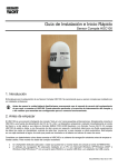
1. Introduction Congratulations on the purchase of your GPS150 Smart GPS/GLONASS Sensor. It is recommended that your receiver is installed by a professional installer. You will need to purchase a suitable 1” x 14 TPI thread mounting bracket for the GPS150. Knowing your position whilst at sea is key to safe navigation. What we now take for granted, was extremely difficult, time consuming and inaccurate. Then, in the latter half of the 20th century, came the electronic positioning systems – Decca, Loran, Transit and in the 1990s, the global positioning system, GPS. Over 20 years have passed since the first GPS receivers were commercially available and in this time the whole world has come to rely on this US funded technology. Now every boat, plane, car and train that we travel on has GPS navigation and even your smart phone can give a GPS position accurate to within 10m, anywhere in the world, at the touch of a button. Much political discussion has taken place over our reliance on GPS technology, to the point where both Europe (Galileo) and China (Compass) are developing their own satellite based navigation systems, which are scheduled to be fully operational by 2020. However, whilst GPS was being developed in the 1980s, there was another competitive system developed in Russia called GLONASS. This system was very much over shadowed by the American GPS system and due to the secrecy surrounding the technology and the difficulties for non-Russian companies to license this technology, it never achieved wide spread commercial use outside of Russia and surrounding countries. During Russia’s difficult financial period between 1989-1999, government spending on their space program was cut by 80% and launching of new GLONASS satellites stopped. With relatively short life spans the GLONASS satellites soon started to fail and by 2001 there were only 6 satellites still operational and the GLONASS service effectively ceased. Most observers at the time thought this would be the death of GLONASS but in 2000, with the Russian economy recovering, President Vladimir Putin took a special interest in GLONASS and made the restoration of this service a high priority. Between 2002-2011, a large investment was made and at the end of 2011 GLONASS was fully restored and now offers worldwide coverage (with 24 operational satellites) and accuracy almost as good as GPS. In areas of high Latitudes (North and South) GLONASS is more accurate than GPS due to the orbital position of the satellites. Now with the GPS150 DualNav™ technology, boat owners can have a single sensor that will automatically read satellite data from both GPS and GLONASS constellations, choosing the best signals from over 50 satellites. Wherever you are in the world you now have twice the satellites to choose from resulting in the GPS150 receiver having much better coverage, time to first fix and positional accuracy. Add to this the new high sensitivity receiver design, selectable baud rate and 10Hz position update rate and you have a GPS receiver that is significantly better than every previous marine GPS receiver on the market. The new performance is particularly noticeable if the receiver is mounted below deck/inside the wheelhouse where the high sensitivity receiver still gives a good position fix or when there are obstructions blocking the view of the sky, such as a wet sail shadowing the antenna or when sailing in rivers or close to cliffs, plus DualNav™ technology with more satellites to choose from, gives a much more accurate fix. On larger boats, it is now possible to have two completely separate position sources, not just two GPS units but two different positioning systems so that you can compare and validate your actual position. Set one GPS150 to GPS mode and another GPS150 to GLONASS mode and you have dual redundancy and two independent positioning systems. The GPS150 also supports SBAS (Satellite-Based Augmentation System) which is the generic name given to the differential signal transmitted by various local geo-stationary satellites. SBAS allows the GPS150 receiver to remove errors in the position due to environmental conditions and improves accuracy down to <1m. Using WAAS in the US and EGNOS in Europe the GPS150 will automatically switch to differential SBAS mode when available. The GPS150 will also be able to utilise, with a software update, the European funded Galileo positioning system when it comes on line (IOC – Initial Operation Capability) in 2018. Before operating the unit you should also familiarise yourself again with the user manual of the equipment that you are connecting the GPS150 to. Pay particular attention to the GPS Interfacing section and any settings that need to be configured for correct operation. Quick Start Guide for GPS150 V1.02 TEL + 44 1179 554474 www.digitalyacht.co.uk [email protected] 2. Before you start The GPS150 is a smart “all in one” GPS/GLONASS receiver solution for small boats featuring our DualNav™ technology that allows the unit to be set to use the GPS or GLONASS satellite constellations or a combination of the two systems. Select the mode you want the GPS150 to operate in, connect it to a 12v or 24v DC supply and it will immediately start calculating your position and outputting this data in NMEA 0183 format (4,800, 38,400 or 115,200 baud). Carefully consider how you wish to connect the GPS150 to your existing navigation system before you start installing cables. To display the GPS/GLONASS data you will need: Suitable dedicated chart plotter that can read and display GPS/GLONASS data via NMEA0183 ® ® Or a suitable PC Navigation software running on a PC with Microsoft Windows XP /Windows 2000 or Windows ® ® Vista /Windows 7 with a free RS232 serial port or a free USB port with a USB to NMEA adaptor. 3. Installation Before starting installation select a suitable location for the GPS150 Receiver. The unit is water proof and designed for on-deck mounting. The GPS150 antenna has the popular 1” x 14 TPI thread mount, found in many VHF antennas. A wide variety of different brackets are available for this type of threaded mount, consult your local marine electronics dealer or chandlery for more information. The 1” x 14 TPI thread mount can also be removed by unscrewing the three hex bolts with a suitable Allen Key, allowing the GPS150 to be flush mounted on a flat horizontal surface. In this situation, the antenna should be mounted on a layer of silicone sealant to avoid standing water accumulating under the antenna. Dimensions; The GPS150 is supplied with 10m of cable and this should be routed through the vessel to a suitable dry internal location where it can be connected to the boat’s DC power system and the equipment it will be interfaced with. The cable can be shortened, lengthened or joined without problems. Quick Start Guide for GPS150 V1.02 TEL + 44 1179 554474 www.digitalyacht.co.uk [email protected] The GPS150 should be connected to the boat’s DC supply via a 1 Amp fuse. The unit requires 9.6V to 28.8V supply voltage. The GPS150 has a number of operating modes that can be set by adjusting four DIP switches inside the unit. Section 4 of this manual explains how to select the different modes. By default the GPS150 will output; - GLL, GGA, RMC, VTG, GSA, GSV and ZDA once per second at 4800 baud (using GPS Satellites only) This default mode is good for most applications and is exactly the same as our previous GPS105 unit, which the GPS150 replaces. Below are the wiring details for the GPS150 and a connection diagram that shows how to interface to other navigational equipment. Wiring Colours; Red Black Yellow Green Power + (12v or 24v) Power – (0v) NMEA Out + NMEA Out – When connecting to a two wire NMEA Input (such as Raymarine), connect the GPS150 Yellow wire to the NMEA + Input and the Green wire to the NMEA – Input. When connecting to a single wire NMEA Input (such as Garmin), connect the GPS150 Yellow wire to the NMEA + Input and the Green wire to the Power – (0v). Quick Start Guide for GPS150 V1.02 TEL + 44 1179 554474 www.digitalyacht.co.uk [email protected] The GPS150 can be connected to a computer via a USB to NMEA adaptor. If you use the Digital Yacht NMEA to USB Adaptor, then the diagram below shows how to connect them together. The GPS150 can also be used wirelessly to send GPS data to an iPad/iPhone or Android device by using one of Digital Yacht’s WLN10 (4800 baud) or WLN10HS (38400 baud) Wireless NMEA Servers. The GPS150 should be connected to the WLN10/WLN10HS as shown in the diagram below. Quick Start Guide for GPS150 V1.02 TEL + 44 1179 554474 www.digitalyacht.co.uk [email protected] 4. Mode Selection The GPS150 can be operated in a number of different modes, for example; GPS at 4800 baud for legacy systems GPS+GLONASS at 38400 baud for new plotters “Turbo Mode” at 115K baud for PC race software Selection of the operating mode is via four “DIP” switches inside the unit. Changes to the switches will become active when the GPS150 is power cycled (turned off/on). There is a green LED on the PCB that indicates if the GPS is working correctly and the baud rate selected. The photo of the PCB shows the location of the LED and switches. Within 2-3 seconds of applying power to the GPS150, the LED should illuminate as follows; LED State Description LED ON Configured correctly for 4800 baud LED Slow Flash Configured correctly for 38400 baud LED Quick Flash Configured correctly for 115K baud (Turbo Mode) LED Flashes once every 2 seconds Unused Mode Selected (check DIP switches) LED Flashes twice every 2 seconds Power Up Sequence Failed* * NOTE – In some situations, where the switching of the power to the GPS150 is not cleanly made or it is made to quickly (not giving the internal voltages time to dissipate), the GPS150 Power Up Sequence may fail resulting in the selected operating mode not being setup correctly. This situation is indicated by the LED flashing twice every 2 seconds. Should this occur, simply turn off the GPS150 wait 10 seconds and then power it up again. If it continues to not power up correctly then contact Digital Yacht for further advice, To access the switch, it is necessary to open the GPS150. It is recommended that this operation is only carried out by an approved Digital Yacht Dealer/Distributor, any physical damage to the PCB will not be covered by warranty. Before opening the GPS150, turn off all DC power to the unit and then remove the threaded mount by unscrewing the 3xM3 hex bolts using a suitable Allen Key. Then using a Torx T6 screwdriver, remove the three screws that hold the GPS enclosure together. Gently pull the enclosure apart being careful not to lose the O-Ring seals (1 large outer and 3 small screw pillar O-Rings). Once the GPS150 PCB is exposed, set the four switches to the relevant positions for the required operating mode as shown in the table on the next page . Quick Start Guide for GPS150 V1.02 TEL + 44 1179 554474 www.digitalyacht.co.uk [email protected] Operating Modes Switches MODE 1234 SATELLITES BAUD RATE NMEA DATA GPS 105 Mode (default) GPS 4800 1 HZ GGA/GLL/RMC/GSV/GSA/VTG/ZDA GPS 6Hz Mode 4800 Baud GPS 4800 6 HZ RMC GPS+GLONASS Minimum Sentences GPS+GLONASS 4800 1 HZ RMC/GSV/GSA GPS+GLONASS All Sentences 1Hz GPS+GLONASS 38400 1 HZ GGA/GLL/RMC/GSV/GSA/VTG/ZDA GPS+GLONASS All Sentences GPS+GLONASS 38400 6 HZ GGA/GLL/RMC/GSV*/GSA*/VTG/ZDA* GPS+GLONASS Standard Sentences GPS+GLONASS 38400 10 HZ GGA/RMC/GSV*/GSA* GLONASS 1Hz All Sentences GLONASS 4800 1 HZ GGA/GLL/RMC/GSV*/GSA*/VTG/ZDA* GLONASS 6Hz Minimum Sentences GLONASS 4800 6 HZ RMC Full "Turbo" Mode GPS+GLONASS 115000 10 HZ GGA/GLL/RMC/GSV*/GSA*/VTG/ZDA* * These sentences output at 1HZ After changing the DIP switches, it is necessary to power cycle the GPS150 (turn off/on) before the new operating mode becomes active. Check the LED to make sure that the expected baud rate is active. Quick Start Guide for GPS150 V1.02 TEL + 44 1179 554474 www.digitalyacht.co.uk [email protected] 5. Technical Specification Receiver Sensitivity Update Rate Accuracy Position Accuracy Velocity Time Differential GPS Time to First Fix Technology Supported Maximum Altitude Maximum Velocity Operating Temperature Maximum Current Dimensions Weight Protocols NMEA messages Power Input Cable GNSS L1 C/A-code, SPS of GPS + Glonass, Galileo or Beidou -165 dBm typical 1Hz by default (configurable up to 10Hz) <1m with SBAS and 3.0-5.0m without SBAS typically (67%) 0.02m/sec typically (50%) ± 1us SBAS (WAAS, EGNOS, MSAS, GAGAN and QZSS) 23sec (typical) GPS and GLONASS (Galileo and Beidou with firmware update) 18,000m 1000 knots -40°C to +85°C degrees Celsius 30mA (@12Volts) 75mm diameter, 82.5mm high (with mount), 32mm high (no mount) 300g NMEA-0183 Version 3.01 GGA, GLL, RMC, VTG, GSA, GSV, ZDA VDC +9v to 34v White 10m Shielded Cable (4.5mm OD) Quick Start Guide for GPS150 V1.02 TEL + 44 1179 554474 www.digitalyacht.co.uk [email protected]