1
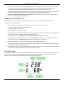
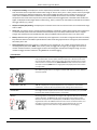
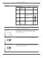
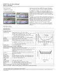
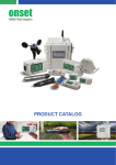
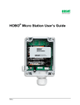
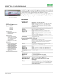
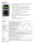
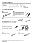
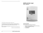
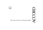
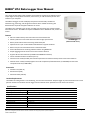
HOBO® U14 Data Logger User Manual The U family of data loggers offers reliability and convenient monitoring for applications that require higher accuracy, better resolution, more memory, or USB connectivity for fast data readout to your computer. The HOBO U14 logger records and displays temperature and humidity conditions in manufacturing, processing, and storage environments where reliable monitoring and documentation of specific temp/RH conditions are critical. The HOBO U14 is available in two versions: U14‐001 with internal sensors and the U14‐002 with external sensors. The HOBO U14 requires HOBOware® Pro or HOBOware Lite, Version 2.5 or later. Features 64k non‐volatile memory that retains data even if the batteries fail Memory indicator on LCD shows how much data storage space remains Battery Level indicator shows remaining useful battery life U14 Data Logger (Model U14‐001 shown) Operates for one year on three alkaline AAA batteries in typical conditions Built‐in relay for use with Remote Alarm or Automatic Dialer Direct USB interface for launching and data readout using HOBOware Sample (logging) interval can be set from one second to 18 hours Supports Onset’s Data Assistants (available with HOBOware software) Can be used with the Onset U‐Shuttle (U‐DT‐1) Internal sensor model (U14‐001) has internal temperature and relative humidity sensors with 12‐bit resolution External sensor model (U14‐002) supports the 12‐bit Temperature/10‐bit RH Sensor (S‐THB‐M00x) and the 12‐bit Temperature Sensor (S‐TMB‐M00x) Accessories Outdoor Case (CASE‐4x) Remote Alarm (ARA) Automatic Dialer (AVD‐45) Location Requirements The HOBO U14 is designed for a non‐condensing, non‐corrosive environment. Keep the logger dry. Some external sensors can be placed in harsher environments than the logger. See the external sensor specifications in the sensor user manual. Specifications Environmental Operating temperature range ‐20°C to +50°C, (‐4°F to +122°F) , 0 to 100% RH non‐condensing Operating relative humidity range 0 to 95%, non‐condensing, non‐corrosive environment Logger Capabilities Capacity Temp and RH: 21,500 measurements; Temp Only: 43,000 measurements Software‐selectable sampling intervals 1 second up to 18 hours, recording times up to 1 year Start Programmable start time/date Recording modes Stop when full Launch Modes Immediate, Delayed Memory Nonvolatile EEPROM memory retains data even if batteries fail © 2010–2012 Onset Computer Corporation. All rights reserved. Onset, HOBO, and HOBOware are trademarks or registered trademarks of Onset Computer Corporation for its data logger products and configuration/interface software. All other trademarks are the property of their respective companies. 13416‐C MAN‐U14‐00x Distributed by MicroDAQ.com, Ltd. www.MicroDAQ.com (603) 746-5524 HOBO U14 Data Logger User Manual Specifications LCD Size 33 x 50.8 mm (1.3 x 2 inches) Elements Temperature and relative humidity simultaneously °C or °F (selectable within host software) Memory remaining and battery level Flashing ALERT for out‐of‐limits conditions (selectable within host software), which stops flashing on offload or return to normal range Alarms Set points High and low set points for both temperature and relative humidity with selectable delays Reset options Alert conditions reset on offload or return to normal range Selectable Contact Relay Normally Closed or Normally Open Contact rating 48VDC, 1A max Contact resistance Less than 1 Ohm Range 0% Low Battery Range Communications Method Offloads data to PC or U‐Shuttle via USB cable Speed Readout full logger (64K) in less than 30 seconds Time accuracy ±1 minute per month at +20°C (+68°F) Power 3 AAA Alkaline batteries, user‐replaceable Dimensions 125 x 92 x 31 mm (4.9 x 3.6 x 1.2 in) Weight 170 g (6.0 oz) with batteries Internal 12‐Bit Temperature Sensor Measurement range ‐20°C to +50°C (‐4°F to +122°F) Accuracy ±0.21°C from 0° to 50°C (±0.38°F from 32° to 122°F); ±0.13°C (0.24°F) typical (see Plot A) Resolution 0.02°C @ 25°C (0.04°F @ 77°F) (see Plot A) Response time 15 minutes (to 90% in airflow of 1 m/sec) Temperature Accuracy Drift Negligible Internal 12‐Bit Relative Humidity Sensor (User replaceable) Measurement range 0‐100% RH, ‐20 to 50°C (‐4 to 122°F) Accuracy +/‐ 2.5% from 10% to 90% RH (typical), to a maximum of +/‐ 3.5% including hysteresis (see Plot B) Resolution 0.03% RH @ 25°C (77°F) Response time 2 minutes (to 90% in airflow of 1 m/sec) Accuracy Drift <2% over 5 years typical Hysteresis 1% Typical External Sensors For External Sensor Specifications, see the sensor’s user manual Battery Life The batteries will last one year in typical conditions (logging intervals of ≥ 1 minute with weekly offloads and average temperatures greater than 10°C or +50°F). Frequent offloads and/or extreme temperatures will reduce battery life. At temperatures below freezing (0°C or +32°F), batteries will typically require replacement every six months. In these conditions the battery level bar graph should be checked regularly. See Battery Level Indicators on page 8. The CE Marking identifies this product as complying with all relevant directives in the European Union (EU). Temperature Accuracy and Resolution The maximum reading error for the internal temperature sensors is shown at right. This is a worst case error. In a typical logger, temperature errors will be substantially lower. NIST certification of temperature accuracy for some sensors is available from Onset. The temperature resolution for internal sensors is also shown at right. Resolution is the smallest difference between adjacent temperature steps that the logger can report. The logger will typically experience little or no accuracy drift unless the electronic components or temperature sensor are damaged mechanically or by exposure to environmental factors beyond the specifications, such as high heat and humidity. Plot A: Internal Temperature Sensor Accuracy and Resolution 2 Distributed by MicroDAQ.com, Ltd. www.MicroDAQ.com (603) 746-5524 HOBO U14 Data Logger User Manual Internal Relative Humidity Accuracy Temperature compensated. Do not expose the internal RH sensor to fog, mist, or other condensing conditions. The logger’s relative humidity accuracy for the internal model is shown in the plot at right. Plot B: Internal RH Sensor Accuracy Components Front Back LCD Screen. See The LCD Screen section for details. USB Port. Use an Onset‐ supplied USB interface cable to connect the HOBO U14 to a computer. Mounting Holes. Use mounting screws 2.5 cm (1 inch) apart to mount the U14 to a wall. External Sensor Port (Model U14‐002 Only). Connect supported Smart Sensor here. Battery Compartment. The HOBO U14 requires three AAA batteries. Onset Computer Corporation strongly recommends the use of fresh alkaline batteries. Batteries should be replaced when the BATT LEVEL bar graph is down to one segment, which indicates 20% battery life or less. Circuit Board Replaceable Internal RH Sensor (Model U14‐001 Only). The internal relative humidity sensor in the U14‐001 may require replacement if it is damaged mechanically or by exposure to condensation or chemicals. The replacement sensor (part number HUM‐RHPCB‐3 or RHPCB‐3A) is available from Onset or an Onset Authorized Dealer. See the last page for more details. Relay Terminal (for Remote Alarm or Automatic Dialer). The HOBO U14 is compatible with Onset’s Remote Alarm (part number ARA) and Automatic Dialer (part number AVD‐45) available from Onset Computer or an Onset Authorized Dealer. See the next section for more details. 3 Distributed by MicroDAQ.com, Ltd. www.MicroDAQ.com (603) 746-5524 HOBO U14 Data Logger User Manual Setting Up the HOBO U14 Follow these instructions for setting up and launching the HOBO U14 logger. 1. Insert the three AAA batteries. Remove the battery door on the back of the unit and insert the batteries in the proper direction. 2. If you are using a Remote Alarm and/or Automatic Dialer, connect it to the HOBO U14 now. Otherwise, replace the battery cover and go to step 3. The HOBO U14 is compatible with Onset’s Remote Alarm (part number ARA) and Automatic Dialer (part number AVD‐ 45) available from Onset Computer or an Onset Authorized Dealer. See the product’s user manual for complete details. The interconnect wire range is 22AWG to 14AWG. To connect a Remote Alarm or Automatic Dialer to the HOBO U14: a. Loosen the two screws on the relay terminal. (Remove the battery door if necessary.) b. Feed the wires through the small hole at the bottom of the case. c. Feed the wires through the holes in the relay terminal. d. Tighten the screws on the terminal. e. Replace the battery compartment cover. f. Connect the wires to the Remote Alarm or Automatic Dialer using the following wiring diagrams as guides. All three drawings show the logger in the Normally Closed state with the Alert inactive. The HOBO U14’s contact closure is initially set at the factory to be Normally Closed, but you can change this in HOBOware to accommodate Normally Open devices (see the ARA User’s Manual). If the alert output is connected to a remote alarm configured for Normally Closed inputs, you can avoid false alarms when the logger is disconnected by making a temporary connection between the wires going to the remote alarm. Be sure to disconnect this temporary connection when the logger is reconnected to the remote alarm wires. HOBO U14 with Onset’s ARA Remote Alarm HOBO U14 with Onset’s AVD‐45 Automatic Dialer NOTE: The polarity of the connections to the logger does not matter. NOTE: The polarity of the connections to the logger does not matter. 4 Distributed by MicroDAQ.com, Ltd. www.MicroDAQ.com (603) 746-5524 HOBO U14 Data Logger User Manual HOBO U14 with Onset’s ARA Remote Alarm and AVD‐45 Automatic Dialer NOTE: The polarity must be as shown. 3. If you have an External Sensor model (U14‐002): Plug the external sensor into the RJ‐12 jack on the side of the HOBO U14. Hold the black rubber flap down against the connector so it slides into the port. NOTE: The sensor readings will not be displayed until the logger is launched (immediate or delayed) or the status is checked using either HOBOware or the U‐Shuttle. The readings will not be logged until you launch the logger later in this procedure. 4. Connect the U14 to a computer running HOBOware. Plug the large end of the USB cable supplied with HOBOware into a USB port on the computer and plug the small end of the cable into the side of the HOBO U14. If the logger has never been connected to the computer before, it may take a few seconds for the new hardware to be detected (Windows only). 5. Start HOBOware and open the Launch window. From the Device menu, select Launch. Configure Launch parameters, including a Launch description, logging interval, and start time. Click Help in HOBOware for details on Launch parameters. 6. Configure Alarms (optional). Use the Alarm feature to flash a warning on the LCD if the monitored temperature or relative humidity falls outside user‐selectable limits. If the temperature or RH measured by the logger falls outside the selected high or low limit, the word ‘Alert,’ an alert symbol, and the temperature or RH measurement that went out of limits will flash. 7. If you require remote or secondary notification of an alarm condition, you can connect a remote audio alarm and/or an Automatic Dialer to the contact closure as described in Step 2. To access the Alarm feature, click the Alarms button in the Launch window, which opens the following dialog box. 5 Distributed by MicroDAQ.com, Ltd. www.MicroDAQ.com (603) 746-5524 HOBO U14 Data Logger User Manual a. Enable Sensor Alarms. To enable a sensor alarm, select the desired sensor in the Channel box, and then select the check box for the High Alarm and/or the Low Alarm. Enter a value to define the alarm threshold. You can enter a value in the box or use the sliders. (If you enter values manually, the software may adjust them slightly to the nearest values supported by the logger.) You can also set the number of samples (30 seconds per sample) that must be displayed before the alarm will be triggered. b. Set Number of Samples. To avoid unintended activation of the relay contact, set the number of samples to allow for anticipated breaches of the alarm threshold. If the alarm is tripped and the number of samples is set to more than 1, the LCD will indicate Alert Delayed. If the measurement is still out of range when the number of samples is reached, the relay contact will be activated. Note about Avoiding Unintended Relay Activation. In some applications, the environment in which the logger is launched is in immediate violation of the desired alarm limit and will cause an unintended opening or closing of the contact relay. For example, setting an upper alarm limit of +32°F for a freezer application and then launching the logger in a room at room temperature will cause an immediate alarm trigger. In this situation, enable a Delayed Launch or select a number of samples that will result in a long enough delay to allow time to transport, mount, and stabilize the logger in the desired location. Other causes of invalid alarms would be freezer doors being opened frequently or defrost cycles. To avoid these, set the number of samples to allow for small periods of time where the value is outside the range, but where the alarm will not be tripped unless the value is outside the range for a significant number of samples. c. Low Battery Alarm. Select the Battery Alarm checkbox to enable the Battery Alarm, which will trigger if the battery drops to 0%. d. Alarm Reset. Select whether the alarm will be deactivated when the Host has relaunched the logger or when the sensor reading has returned within limits. e. Set Relay Contact. If you are using an external device that will be triggered by an alarm (such as a Remote Alarm or Automatic Dialer), set the desired default relay contact state to either Normally Closed (relay opens during an alarm condition, which is the default) or Normally Open (relay closes during an alarm condition) The ARA Remote Alarm can be set to Normally Closed or Normally Open (see remote device User’s Manuals for more details). NOTE: The AVD‐45 Automatic Dialer requires the logger’s contacts to be set to Normally Closed. f. Test the Relay Alarm. Use the Test Set Alarm button to test the relay alarm function. When you click the Test Set Alarm button, the logger will activate the alarm and change the condition of the contact closure. When you click the Test Set Alarm button, it changes to the Test Clear Alarm button. Click the Test Clear Alarm button to deactivate the alarm. NOTE: When testing the alarm with the AVD‐45 Automatic Dialer, Onset recommends that you maintain the alarm for up to 7 minutes to ensure that the AVD‐45 Automatic Dialer completes its dial‐out sequence (see AVD‐45 Automatic Dialer User’s Manual for details). 8. Click the Launch button in HOBOware to launch the HOBO U14. NOTE: If you remove the external sensor on the U14‐ 002 model after logging starts, you will need to relaunch the logger if you reconnect a sensor. 9. Disconnect the HOBO U14 from the computer by unplugging the USB cable. 10. Transport the logger to deployment site. 11. Mount the logger. The HOBO U14 is designed for a non‐condensing, non‐corrosive environment. Make sure the logger is installed in a location where it will remain dry. Some of the external sensors can be placed in harsher environments (see the sensor manual for specifications). a. Mark the wall for the placement of the two mounting screws 2.5 cm (1 inch) apart (vertically). b. Screw in mounting screws, leaving a gap between the wall and the head of the screw of about 0.5 cm (3/16 in.). c. Attach logger by aligning it with the screws, and then push in and down to lock in place. 12. If you have an External Sensor model (U14‐002), mount the External Sensors (see the sensor user manual). 6 Distributed by MicroDAQ.com, Ltd. www.MicroDAQ.com (603) 746-5524 HOBO U14 Data Logger User Manual In some applications (such as a refrigerator, freezer, clean room) it may be more convenient to permanently mount an external sensor at the site. Be sure to place the remote sensor in a location that is representative of the target measurement location and allows free flow of air (beware of any drafts caused by vents, doors, etc). If you permanently mount the sensor and later have to disconnect it from the logger for readout, select Delayed Launch when you relaunch the logger to allow time to reconnect the sensor before the actual launch time. 13. Read out the HOBO U14 as described in the next section. When the memory is full, or anytime you want to view the data, read out the HOBO U14 using HOBOware. Reading Out the HOBO U14 NOTE: If you are using the U‐Shuttle to read out the logger, see the U‐Shuttle User Manual for specific instructions. To offload data from the HOBO U14: 1. Optional: Disconnect the logger from the external sensor, Remote Alarm or Automatic Dialer. 2. Transport the logger to the location of the computer. 3. Connect the logger to the computer. 4. Open HOBOware software on the computer. 5. Optional: If you have more than one logger connected to the computer, connect to the HOBO U14 by selecting Device > Select and then select the HOBO U14 from the Select Device window. 6. From the main menu, click the Readout icon (or select Device > Readout from the main menu). 7. If the logger is currently logging, you can choose to continue logging while offloading or stop logging. The readout will begin. The status bar in the Readout Logger window will indicate the percentage complete. 8. When prompted, enter a name for the file and click Save. The Plot Setup Dialog appears. 9. Click Plot to view the graph of the data. See the HOBOware User Manual or On‐line Help for more details on graphing, time selection in plots, and exporting data files. 10. To redeploy the logger, re‐launch it with a delayed start allowing enough time to return the logger to the site, reconnect external devices if any (External Sensors, Remote Alarm, Automatic Dialer). The LCD Screen After installing the batteries, the LCD will display all segments for five seconds. Thereafter, the LCD will display temperature and % RH information. The values on the LCD screen refresh every 30 seconds. The following is an overview of the LCD screen elements. For more details on individual elements, see LCD Indicators for more details. 7 Distributed by MicroDAQ.com, Ltd. www.MicroDAQ.com (603) 746-5524 HOBO U14 Data Logger User Manual Temperature Reading. This displays the current temperature (Fahrenheit or Celsius as selected in HOBOware) on the LCD. Internal sensor has temperature measurement range of ‐20°C to +50°C (‐4°F to +122°F). Notes: There may be slight variations between the displayed temperature value and the logged value due to limits in display conversions. The values seen in HOBOware and the U‐Shuttle are the actual recorded values and the most accurate. The displayed temperature on the LCD screen may be ±0.3°C (±0.6°F) different than the logged value. Fahrenheit values of 200° and higher are displayed as three digits without a decimal (e.g., 205°F); however, the full resolution value will be recorded in the logger memory (e.g., 205.4). Relative Humidity (RH) Reading. This displays the current RH on the LCD. The internal sensor has a measurement range of 0% to 100%. Alarm Icon. This displays alerts as configured within HOBOware. Specifically, ALERT indicator signals when temperature or relative humidity limits have been exceeded. ALERT DELAYED if you have delay enabled and an alarm is tripped. Triangle with exclamation mark immediately after delay (if enabled) indicates that the relay is in an alarm state. Battery Level. Remaining battery level is indicated by a five‐segment bar. The number of segments decreases as battery level decreases. Batteries should be replaced when the BATT LEVEL bar graph is down to one segment, which indicates 20% battery life or less. Remaining Memory. Remaining memory is indicated by a five‐segment bar. The number of segments decreases as remaining memory decreases. NOTE: If the memory is full, the logger will no longer log. The logger will continue to monitor conditions however, and will trigger an alert if the reading falls outside of the configured range. You must readout the logger and then relaunch it using HOBOware to resume logging. LCD Indicators Alarms If the temperature or RH measured by the logger falls outside the selected high or low limit, the word ‘Alert,’ an alert symbol, and the temperature or RH measurement that went out of limits will flash. If you set the number of samples to greater than 1 and the measured value is outside the limits, ALERT DELAYED will flash until either the number of samples is reached (ALERT with a triangle symbol is displayed) or the alert condition no longer exists. Battery Level BATT LEVEL bar graph down to one segment indicates 20% battery life or less. Batteries should be replaced. Condensation (100% RH) 100% RH is displayed if a temperature/RH sensor is connected and is covered with condensation. The sensor will not provide accurate readings until it has dried out. Unread Data If the logger has been stopped, either manually or because the memory is full, the MEM LEFT hash marks will blink indicating there is unread data. Memory Remaining memory is indicated by a five‐segment bar. Segments decrease as remaining memory decreases. The MEM LEFT bar graph will decrease as the memory is filled. When the memory has been completely filled, the MEM LEFT display will flash and all segments will be off. The HOBO U14 will continue to monitor conditions however, and will trigger an alert if the reading falls outside of the configured range. You must readout the logger and then relaunch it using HOBOware to resume logging. 8 Distributed by MicroDAQ.com, Ltd. www.MicroDAQ.com (603) 746-5524 HOBO U14 Data Logger User Manual LCD Indicators Memory Display States State Stopped MEM LEFT Hash marks On Segments Illustration None Launched/ Logging On Number of segments depends on memory remaining. Highest segment flashes. Launch Delaying Flashing All On/Flashing Memory Full Flashing All Off (until data is downloaded) External Sensor Removed If an external sensor is disconnected from the logger, the logger will record values of ‐ 888.88°C/‐888.88 °F for temperature and 0% RH. No External Sensor If the U14‐002 logger is launched and no external sensor has been connected, the display will show dashes “‐‐‐” and will log false values (‐888.88°C/‐888.88°F for temperature and ‐888.9% for RH). Temp Only Sensor Installed If a temperature‐only sensor is connected, no RH value will be displayed. No RH Sensor Installed but Channel Active A display of ‐‐% RH indicates that the humidity channel is active in the software and should be turned off to maximize memory space. Otherwise, the unit will record a ‐ 888.9% RH value at every logging interval 9 Distributed by MicroDAQ.com, Ltd. www.MicroDAQ.com (603) 746-5524 HOBO U14 Data Logger User Manual Maintenance Replacing Batteries The HOBO U14 requires three AAA batteries. Onset Computer Corporation strongly recommends the use of fresh alkaline batteries. Batteries should be replaced when the BATT LEVEL bar graph is down to one segment, which indicates 20% battery life or less. To ensure data integrity, use HOBOware to read out the logger and stop logging before changing batteries. Replacing the Internal RH Sensor (Model U14‐001 Only) The internal relative humidity sensor in the U14‐001 logger may require replacement if it is damaged mechanically or by exposure to condensation or chemicals. The replacement sensor (Part No. HUM‐RHPCB‐3A) is available from Onset or an Onset Authorized Dealer for U14‐001 loggers with serial numbers above 9847173. Note: U14‐001 loggers with a serial number below 9847173 require a different replacement sensor (Part No. HUM‐RHPCB‐3). You can replace the internal RH sensor yourself or have it replaced as part of a U14‐001 tune‐up/calibration service (available from Onset). Contact Onset for more details. Onset Computer Corporation www.onsetcomp.com Mailing Address: P.O. Box 3450 Pocasset, MA 02559‐3450 Phone: 1‐800‐LOGGERS (1‐800‐564‐4377) or 508‐759‐9500 Fax: 508‐759‐9100 Hours of Operation: 8 AM to 5 PM ET, Monday through Friday Email: [email protected] 10 Distributed by MicroDAQ.com, Ltd. www.MicroDAQ.com (603) 746-5524