1
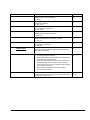
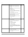
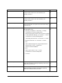
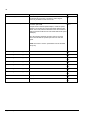
NS100 Sway control Supplement Sway control with ABB ACS880 Crane control (+N5050) 2 NS100 Sway control Supplement Sway control with ABB ACS880 Crane control (+N5050) MAN3920151001 Rev A EN EFFECTIVE: 2015-09-23 FIDOS\YATDM1 2015 NOSWING. All rights reserved. Table of contents Table of contents............................................................................................................................ 3 Introduction to this manual ........................................................................................................... 5 Chapter overview ............................................................................................................................. 5 Safety instructions ............................................................................................................................ 5 Compatibility..................................................................................................................................... 5 Reader ............................................................................................................................................. 5 Contents ........................................................................................................................................... 5 Related documents .......................................................................................................................... 6 Product and service inquiries............................................................................................................ 6 Providing feedback on manuals........................................................................................................ 6 Document library on the internet....................................................................................................... 6 Start-up and control ....................................................................................................................... 7 Checklist for a Quick Start-up ........................................................................................................... 7 Figure 3. NS100 and ACS880 Connection example. ................................................................... 8 Program features............................................................................................................................ 9 Chapter overview ............................................................................................................................. 9 Overview of the Sway function ......................................................................................................... 9 How does the NS100 Sway control operate? ................................................................................. 10 Initial sway correction while starting ........................................................................................... 10 Sway correction while moving load ............................................................................................ 10 Sway correction while stopping .................................................................................................. 10 Straight up lifting ........................................................................................................................ 10 Follow me .................................................................................................................................. 10 Limit switches ............................................................................................................................ 11 Commissioning instructions for Sway function......................................................................... 12 How to decide mounting direction: .................................................................................................. 12 Workflow for easy setup of drives direction command: ................................................................... 12 Long travel setup ....................................................................................................................... 12 Trolley setup .............................................................................................................................. 12 Mechanical mounting. .................................................................................................................. 13 Electrical installation guide ......................................................................................................... 16 Fieldbus communication settings ............................................................................................... 17 4 NS100 communication ....................................................................................................................17 Crane fieldbus control .....................................................................................................................18 Signals and parameter ..................................................................................................................19 Chapter overview ............................................................................................................................19 Terms and abbreviations .................................................................................................................19 Group 9 Added signal from sway control .........................................................................................20 Group 78 External sway control.......................................................................................................20 Examples of typical connections and parameter settings .........................................................25 Chapter overview ............................................................................................................................25 Automatic system identification ...................................................................................................25 Straight Up Lifting schematics.....................................................................................................26 Functionality of Straight up lifting function ..............................................................................26 Straight Up Lifting interacting with hoist control schematics ........................................................27 Functionality of Straight up lifting function interactive with hoist ..............................................27 Follow me schematics ................................................................................................................28 Functionality of Follow me function.........................................................................................28 Detailed information on the product. ................................................................................................29 Led lamps signaling.........................................................................................................................30 Product safety .................................................................................................................................30 No Swing™ hardware module has undergone the following tests: ..............................................30 Environmental safety ..................................................................................................................30 Warranty and liability information................................................................................................31 FAQ/Troubleshooting ...................................................................................................................31 Introduction to this manual Chapter overview This chapter describes the contents of the manual. It also contains information on the compatibility, safety and intended audience. Safety instructions Follow all safety instructions delivered with the drive. • Read the complete safety instructions before you install, commission, or use the drive. The complete safety instructions are given at the beginning of the Hardware Manual. • Read the software function specific warnings and notes before changing the default settings of the function. For each function, the warnings and notes are given in the subsection describing the related user-adjustable parameters. Compatibility The manual is compatible with ACS880 Crane control program version 2.0.0.0 or later (version code can be found from a signal 07.07: LOADING PACKAGE VER). Reader The reader of the manual is expected to know the standard electrical wiring practices, electronic components, and electrical schematic symbols. Contents This Sway control with NoSwing NS100 supplement describes the operation and the settings of the sway control functions with ABB ACS880 Crane control program (+N5050). The rest of the program is equal to the ABB ACS880 Crane control program manual which is documented in the Firmware manual,ACS880 crane control program (option+N5050) (3AXD50000027678 [English]). The supplement consists of the following chapters: • Start-up and control points out the items to remember at the drive start-up. It also refers to the related documents for further information. • Program features describes the operation of the Sway control function, the core of the Sway control program. • Describes the user adjustable settings for tuning the operation of the Sway control function. Introduction to this manual 6 Related documents This Sway control with NoSwing NS100 supplement is to be used together with ABB Firmware manual,ACS880 crane control program (option+N5050) (3AXD50000027678 [English]). Hardware Manual (appropriate Hardware Manual is delivered with the drive). Option manuals (appropriate option manual is delivered with the option device). Product and service inquiries Address any inquiries about the product to your local NOSWING representative, quoting the type code and serial number of the unit in question. A listing of NOSWING sales, support and service contacts can be found by navigating to www.noswing.com Providing feedback on manuals Your comments on our manuals are welcome. Go to www.noswing.com . Document library on the internet You can find manuals and other product documents in PDF format on the Internet. Go to www.noswing.com . Introduction to this manual Start-up and control Checklist for a Quick Start-up Step Instruction Additional Information 1. Execute basic crane commissioning ABB ACS880 Crane control program (+N5050) Check brake control and limit switches 2. Install NS100 and MODBUS-communication between ABB ACS880 Check fieldbus-adapter’s strapping settings according adapter’s user’s manual 3. Check NS100 mechanical installation and correct direction. “Long travel: FWD=positive speed reference and trolley: To right =positive speed reference, see picture below 4. In ACS 880 open the hided NS100 settings parameters Password 584 into the parameter passcode 96.02. After the settings, change passcode back to 1. 5. Do the settings according a table on chapter xx 6. Check status indicator from NS100 Green = OK, sway-control activated Blinking Green= OK, but sway-control disabled Blinking RED =No MODBUS-connection Red= General fault 7. Trial run Start-up and control 8 Control operation The drive can be controlled by the panel (local control, during commissioning) or through the external control signal interface (remote control). Switch between local and external control modes with the LOC/REM key on the control panel or with the DriveComposer PC tool. When the Drive is controlled through the fieldbus the commands are given and received over the fieldbus communication link (see chapter Fieldbus communication). How the Sway control program works is described in chapter Program features. Figure 3. NS100 and ACS880 Connection example. Start-up and control Program features Chapter overview This chapter describes the operation of the Sway function. Overview of the Sway function Swing of the load causes problems when a crane is being operated in manual control, particularly if the operator has only little experience. Depending on the mass of the load, quite a significant amount of kinetic energy is bound in the swinging load and may cause dangerous situations or damages either to the load itself or to the environment. By Sway control program, the load and initial sway problems can be essentially reduced without any significant changes in the crane itself. The purpose of the Sway control program is to help to drive the crane manually. For the best result the driver should rather control the load directly, not indirectly by the bridge and/or trolley. The driver can leave the sway compensation task for the frequency converter. Program features 10 How does the NS100 Sway control operate? Initial sway correction while starting When load is lifted and the operator starts to move the load (long travel, trolley or both), NS100 have different modes of sway control. Full correction at start: When NS100 receives start command it finds the best moment to start and starts according to a optimal curve based on the rope angle. This start sequence takes care of possible initial sway at start and minimizes sway caused by the pendulum effect into the full speed run when moving the load. Calculated start: NS 100 ramps up the motors according to a profile that minimizes sway based on the rope angle. Ramp start: Starting according to ramp settings in drive. Sway correction while moving load While load is moving towards its destination NS100 minimizes sway caused by external forces such as wind. Sway correction while stopping When crane operator removes start command, wants to stop. NS100 have different modes of stopping. Full correction at stop: NS100 waits for the best moment to stop and stops according to the optimum ramp down based on the ropes angle speed. This mode removes most of the sway and the load is stable at stop. Due to the stop curve of this mode the load moves a bit after stop command is given. Calculated stop: NS100 stops as fast as possible according to a standard ramp down curve. The curves correction parameter is based on behavior at start and ropes angle speed. This mode stops the load faster but the load can have some sway at stop. Ramp stop: NS100 monitors the stop behaviour but do not make any corrections. Motors ramp down according to drives rampprofile and ramptime. Straight up lifting When this mode is enabled and function started NS100 controls start command and speed reference of both directions. NS100 runs towards zero angle at a predefined speed until zero angle is reached or function start command removed. This function can be integrated to the hoist drive control helping the operator center the lifting point, and make it impossible to lift the load with an angle on the ropes. Follow me When enabeling “Follow me” function, the crane will follow the hook with the rope in almost vertical position during the run. This function is mainly used on small cranes with light loads. Preferable use this function when operator wants to move emty hook across the workshop, the crane will follow the hook in both longtravel and trolley direction, getting there as fast as possible with minimum loadswing at stop. Program features Limit switches The distance to stop the crane from full speed can be estimated by formula (units are SI units): s= v (t + t acc ) 4 Here t is the longest possible pendulum time constant, it can be estimated from the hoisting height: t = 2 sqrt (height) Example: Hoisting height is 16 m and crane full speed is 30 m/min = 0.5 m/s and normal deceleration time for manual driving is 5 sec (Par. 22.02). According to linear ramp the slowdown distance of the crane would be 0.5 x v x t acc = 1.25 m. With Sway engaged the basic ramp time can be set shorter, for example 4 sec (Par. 22.09 ASWAY RAMP TIME [s]). The slowdown distance of the load is in this case: t = 2 x sqrt 16 = 8 s, s = 0.5/4 x (8 + 4) = 1.5 m. Program features 12 Commissioning instructions for Sway function How to decide mounting direction: Sensor is to be mounted in long travel direction, meaning the sensor is aligned so that sensor points in long travel direction when mounted. Workflow for easy setup of drives direction command: Look at the label on sensor for long travel and trolley default directions. Make sure that long travel drive has node number #1 on Modbus. Long travel setup Start long travel drive in rev direction at a slow speed locally or by drives PC software. Check that the crane is moving in rev direction according to label on sensor. DO NOT start motor if there is a risk of personal or structural damage! If the direction matches the label on sensor, switch drive to remote control and continue to test direction from pendant otherwise (note1). Press the button for long travel on pendant and check that crane moves according to markings on pendant and crane. If everything is ok then continue with trolley drive otherwise (note 2). Trolley setup The trolley rev direction is now on your left hand when looking in long travel fwd direction Check that modbus node number is set to #2 Repeat the same procedure as for long travel. First local test to make sure that the motor is turning the right way. Second pendant test to check that the pendant and crane direction markings match. Note 1: If the crane is moving in forward direction when testing locally at low speed (rev), switch motor direction by switching 2 phases on motor or by parameter. Do the test again and make sure the crane is moving in the right direction. Note 2: If the crane is moving in the opposite direction from the markings of the pendant and crane, switch DI1 and DI2 signals on drive. Program features Mechanical mounting. WARNING! Mechanical installation of the No Swing ™ requires operations on altitudes and additional safety measures need to be taken. Before starting the mechanical installation of the No Swing™ ensure that all the risks of operating on altitudes are properly addressed. Follow the safety instructions given in this manual and always refer to the safety instructions of the industrial crane as well as the installed frequency converter for further guidance Note To avoid damages to No Swing™ caused by the hoist winding back and unwinding the wire (hoist reeving), pay particular attention to ensuring the correct positioning the device on the wire. 1. Locate the correct placement of the No Swing™ on the industrial crane (Picture 6) 3. Prepare the snap-on fastening by correctly attaching the screws. 2. Ensure that the device is correctly aligned against the rope with Modbus connection cable facing upwards and led lamp facing downwards (Picture 5) 3. Fasten the device to the rope and ensure that the device is fastened securely 4. Ensure that the device is securely fastened After completing steps 1-4 correctly, the electrical installation can be initiated. Program features 14 Picture 1. Device correctly against the rope. Modbus connection cable facing upwards, led lamp facing downwards. The device is ready to be fastened. Program features Picture 2. Ensuring the correct installation onto the crane. Cable facing upwards, led lamp facing downwards. Program features 16 Electrical installation guide WARNING! All electrical installation and maintenance work should be performed by qualified electricians. The adjoining equipment for No Swing™ (drive, crane) should be properly earthed. Do not attempt any work on a powered crane or drive. After switching off the mains, always allow the intermediate circuit capacitors 5 to discharge before working on the No Swing™ device. Neglecting to take the appropriate safety measures can cause physical injury or death. Note Correct mechanical installation of the No Swing™ is required before starting the electrical installation. 1. A 10 meter long cable is attached to the device, the cable is intended to connect the No Swing™ and the frequency converter or PLC. Please take a moment to identify the five color-coded wires at the other end of the cable (brown +24 VDC; white 0 V; grey Modbus data A; pink Modbus data B; green Modbus gnd; yellow Earth on NS board 2. Locate the Modbus adapter in the frequency converter. The color coded wires (cables) need to be correctly connected to the Modbus adapter. Follow the instructions provided on the product label, for the correct attachment of wires (cables) 3. Follow the instructions provided on the product label in order to attach the color-coded cables to the Modbus adapter. Please remember that this document is specifically crafted to conform to the ACS 880 frequency converter manufactured by ABB. If a different kind of frequency converter is installed always refer to the manufacturer’s instructions for additional reference. Program features Fieldbus communication settings NS100 communication NS100 communication is made by MODBUS-protocol, therefore it needs FSCA-01fieldbus adapter to be installed into the drive. Communication settings is done to the group B, parameter groups 54-56 Fieldbus B settings. See basic settings to the group 54 below: Note ! REMEMBER to check position of termination resistor switch in the fieldbus adapter 54.1 FBA B type RS-485 comm 54.2 Profile ABB Classic 54.3 Station ID Longtravel ID=1, trolley ID=2 54.4 Baud rate 57.6 kbit/s 54.5 Parity 8 None 1 54.6 Modbus timeout 10 54.7 Timeout mode None 54.11 Word order HiLo 54.12 Address mode Mode 0 54.13 FBA B Par13 0 54.14 FBA B Par14 0 54.15 FBA B Par15 0 54.16 FBA B Par16 0 54.17 FBA B Par17 0 54.18 FBA B Par18 0 54.19 FBA B Par19 0 54.20 FBA B Par20 0 54.21 FBA B Par21 0 54.22 FBA B Par22 0 54.23 FBA B Par23 1 54.24 Protocol check 1 54.25 Protocol Modbus. Program features 18 Crane fieldbus control Crane fieldbus control is made selected fieldbus protocol in fieldbus control group A, therefore all settings must be done in groups 51-53. Below is example when used protocol is MODBUS with FSCA-01-fieldbus adapter 51.1 FBA A type RS-485 comm 51.2 Profile ABB Classic 51.3 Station ID 5 51.4 Baud rate 57.6 kbit/s 51.5 Parity 8 None 1 51.6 Modbus timeout 10 51.7 Timeout mode None 51.8 OK messages 35083 51.9 CRC errors 0 51.10 UART errors 0 51.11 Word order HiLo 51.12 Address mode Mode 0 51.13 FBA A Par13 0 51.14 FBA A Par14 0 51.15 FBA A Par15 0 51.16 FBA A Par16 0 51.17 FBA A Par17 0 51.18 FBA A Par18 0 51.19 FBA A Par19 0 51.20 FBA A Par20 0 51.21 FBA A Par21 0 51.22 FBA A Par22 0 51.23 Init status 1 51.24 Protocol check 1 51.25 Protocol Modbus Select control signal sources to be fieldbus, see list below: Program features 20.1 Ext1 commands Fieldbus A 22.11 Speed ref1 source FB A ref1 Signals and parameter Chapter overview This chapter describes the user-adjustable parameters of the Sway function. Only new added parameters and signals are listed here. Descriptions for the rest pf parameters are listed So these parameters are extra to the parameters described in ABB Firmware manual,ACS880 crane control program (option+N5050) (3AXD50000027678 [English] Terms and abbreviations Term Definition FbEq Fieldbus equivalent. Shows how the value on control panel is converted to a integer value when communicated over a serial communication link (fieldbus interface). Def Default value Type Data type B Data type Boolean I Data type integer Pb Data type packed Boolean R Data type real S Data type string Signals and parameters 20 Group 9 Added signal from sway control Index 9.06 Name/Selection Crane speed reference Description Type/Def/FbEq Incoming crane speed reference to the NS100. Type: I Def: 1 Group 78 External sway control Index Name/Selection Description Type/Def/FbEq 78.01 Enable ext sway control Enale, Disable, Other….(pointer connection). Enables the external sway control (will make changes to speed reference logic). NOTE:It is allowed to external sway control provide correction of the speed reference. 78.02 Ext speed corr to drive src Source selection, from which signal is taken speed correction Type: Def: value to the drive. E.g. 47.1. NS100 transmits value to this signal (47.1). 78.03 Direct lift enable With this parameter is selected source to activate direct lift Type: function. E.g DIx or fieldbus control word bit. This information Def: will be sent to the NS100 in 78.20 User status word 1 bit 6. Rising edge activates function. When hook/ropes are in direct line, NS100 sent feedback in 78.50 Ext sway control word 1 bit 4 “Direct Lift Done”. Note: rising edge will start the drive automatically and will keep it run until direct lifting condition is reached or normal command to start motion is received. 78.05 Actual speed unscaled Crane actual speed unscaled (without decimals). 1584.4 rpm Type: I 1584 rpm Def: signal 78.20 User status word 1 The NS100 reads this status word. User can set them Type: according NS100 configuration with parameters 78.30-78.35 Def: (bits 0…) Signals and parameters 0. External sway control enabled 1. Toggle bit (to NS100) 2. Start command is active (from operator) 3. Started, ready to follow reference 4. Speed reference is limited (drive is limiting itself for some reason e.g. torque limit. Source is taken from 6.16.7) 5. Drive is stopped (not modulating) 6. Direct lift command to NS100 (it is connected directly to status of 78.03 Direct lift enable) 7. Reserved for “follow me” 8. Modbus id identified 9. ---15 Free for future use Index Name/Selection Description Type/Def/FbEq 78.30 User status word 1 bit 0 Defines source for 78.20 User status word 1 bit 0 “External sway control is enabled” e.g. TRUE Type: Def: 78.31 User status word 1 bit 1 Defines source for 78.20 User status word 1 bit 1 “Toggle bit (to NS100)” e.g. P.31.215.0 Type: Def: 78.32 User status word 1 bit 2 Defines source for 78.20 User status word 1 bit 2 “Start is active (from operator)” e.g. P.6.198.0 Type: Def: 78.33 User status word 1 bit 3 Defines source for 78.20 User status word 1 bit 3 “Started, ready to follow refererence” e.g. P.6.16.4 Type: Def: 78.34 User status word 1 bit 4 Defines source for 78.20 User status word 1 bit 4 “SPEED REFERENCE IS LIMITED” (Limit bit) e.g. P.6.16.7 Type: Def: 78.35 User status word 1 bit 5 Defines source for 78.20 User status word 1 bit 5 “Stopped (Not modulating)” e.g. P.6.16.6- Type: Def: 78.36 User status word 1 bit 6 HIDDEN signal Defines source for 78.20 User status word 1 bit 6 “DirectLift command (HIDED, connected directly to status 78.03 Direct Lift enable) Type: Def: 78.50 Ext sway control word 1 Control word to crane from NS100. 0. Toggle bit (back from NS100) 1. Keep brake closed (at the moment of the start wait the good time togo, swaying angle 2. Keep start command active (after stop command from operator it is kept drive running to correct swaying) 3. Force reference to zero (if it is needed, speed ref ramp can be forced ro be zero) 4. Direct lift is done (hook/ropes have zero angle) 5. 15 Free for future use Type: Def: 78.51 Timeout delay Timeout delay of external sway control. After stop command Type: T it is waited this time, and if ext sway still working drive will Def: 10s forced to stop (safety issue) Signals and parameters 22 Index Name/Selection Description 78.60 Ext sway configuration word 1 NS100 Configuration words. 0. Enable sway correction at start (during ramp-up, 1=Enable) 1. Enable sway correction at stop (during ramp-down, 1=Enable) 2. Enable measure mode. Measured values will be sent to: Angle->78.67 Angle Speed-> 78.68 Axis acceleration ->78.69 (Note ! This mode disables all other external sway control functions, 1=DISABLE all sway control functions) 3. Direct lift start signal 4. Direct lift start signal connected to this drive Type/Def/FbEq Type: Def: Defines to which drives parameter 78.60 Bit 3 Direct lift start signal is connected) NS100 reads this signal from one drive only! 5. Measure mode filter Disable. If user want to read raw data from sensor in measure mode then set this bit to “1” 6. 15 Free 78.61 Ext sway configuration word 2 NS100 Configuration words. 78.62 Minimum speed for correction 0. Inverse sensor polarity (Can be use only in case that mechanical installation of the NS100 is not possible to install according instructions.) “0”= not inversed, “1”=inversed. 1. Automatic zero angle calibration “0”=Disabled,”1”=Enabled. 2. Trigger zero angle calibration “1”= Activate, After calibration process is done this bit will be set to “0” by NS. Recommended to perform this task after commissioning with the lifting ropes in steady vertical position. 3. 15 Free NS100 Configuration words. Minimum speed for correction in RPM. When motor speed falls below this value NS correction functions are disabled. Signals and parameters Type: Def: Type: Def: Index Name/Selection 78.63 P value for NS correction PID Description Type/Def/FbEq NS100 Configuration words. Type: Def: P value for NS correction PID, value divided by 100 internally. Default “0” 78.64 D value for NS correction PID Type: Def: NS100 Configuration words. D value for NS correction PID, value divided by 100 internally. Default “0” 78.65 Direct lift speed NS100 Configuration words. Direct lift speed RPM. This speed is used when direct lifting is executed only. Type: Def: 78.66 Status_Alarm word1 NS100 Configuration words. NS Status/Alarm word Type: Def: 0. NS ready for operation “0”= Not ready, “1”=Ready. Led behaviour on sensor “Steady Green” 1. NS active (NS sends correction value to drives according to other parameter settings) “0”= Not active, “1”=Active Led behaviour on sensor “Blinking Green” 2. Direct lifting function active. “0”= Not active, “1”=Active 3. Measure mode active. “0”= Not active, “1”=Active 4. Bit4 5. Alarm: Measured angle error. Angle outside sensors measure area. “0”=Ok, “1”=Angle error Check mechanical installation 6. Bit 6 7. Alarm: Sensor Fault. “0”=Ok, “1”=Fault. Led behaviour on sensor “Steady Red” 8. 15 Free 78.67 Ext sway measured value 1 Type: NS100 Configuration words. Angle value, resolution 1/100 degree (filtered), active only in Def: Measure mode. See 78.60 78.68 Ext sway measured value 2 NS100 Configuration words. Angle Speed value, resolution 1/100 degrees/s (filtered), active only in Measure mode. See 78.60 Type: Def: Signals and parameters 24 Index Name/Selection Description Type/Def/FbEq 78.69 Ext sway measured value 3 NS100 Configuration words. Acceleration along the axis, resolution 1/100 G degree, active only in Measure mode. See 78.60 Type: Def: 78.70 Fixed correction span Type: NS100 Configuration words. Def: 0 Correction span RPM Example: Motor nominal speed 3000rpm, maximum speed 3300rpm. 78.70=300, NS corrects the speed reference with values -300 to 300, after the add block in the drive reference chain the reference will be from 2700-3300 RPM at full speed (3000rpm). Zero value means that fixed correction span is not used, sensor will calculate the optimal span from min and max speed. NOTE: Check max. and min. speed limits from the ACS880 (Group 30) 78.71 Configuration Word (Spare) Type: Def: 78.72 Configuration Word (Spare) Type: Def: 78.73 Configuration Word (Spare) Type: Def: 78.74 Configuration Word (Spare) Type: Def: 78.75 Configuration Word (Spare) Type: Def: 78.76 Configuration Word (Spare) Type: Def: 78.77 Configuration Word (Spare) Type: Def: 78.78 HW revision Displays NS100 Hardware revision Type: Def: 78.79 SW version Displays NS100 Software version Type: Def: Signals and parameters Examples of typical connections and parameter settings Chapter overview This chapter lists typical connections and parameter settings for basic setup and functions. Automatic system identification It is very important to set the Modbus id for Longtravel to “1” and Trolley to =”2”. NOTE! Remember to check that Modbus is up and running in connected drives (check ok packages) NS100 identifies who is connected and operating on the Modbus line automatically. When the drives id are identified (#1, #2 or both). NS100 sets the status bit 8 in parameter 78.20, configures communication and function according to the identified drives. Signals and parameters 26 Straight Up Lifting schematics Schematics below shows how control signals are connected and what parameter typically are used. Functionality of Straight up lifting function This way of connecting and parameterisation gives the operator full control over straight up lifting function. When the operator presses the dedicated button on the pendant, drives gives over the control of the cranemotors to NS100. NS100 starts both drives and gives speedreference according to ropeangledifference from zero angle. When both drives have run to the zeroangle position the control returns to the drives, and normal operation resumes. Signals and parameters Straight Up Lifting interacting with hoist control schematics Schematics below shows how control signals are connected and what parameter typically are used. Functionality of Straight up lifting function interactive with hoist This way of connecting and parameterisation automatically runs the straight up lifting function before the load leaves the floor. When the operator presses the Straight up lifting button on the pendant, NS100 disables hoist lift function, waits for lift signal from operator. When operator presses lift button straight up lifting process starts. When zero angle is achieved done signal enables normal host lift function. By releasing the enable button the straight up lifting is aborted. Signals and parameters 28 Follow me schematics Schematics below shows how control signals are connected and what parameter typically are used. Functionality of Follow me function This way of connecting and parameterisation makes the crane follow the movement of the hook. Drive(s) starts when enable button is pressed and monitors the rope angle. When ropeangle deviates from vertical, NS100 gives speedref to drive to reach the zero angle. Deviation is caused by operator that pushes the hook in desired direction and the crane automatically follows. NS100 continously does this as long as enable button is pressed. When enable button is released crane resumes normal operation. This function is mostly used with emty hook or with light load attached to the hook, for fast and easy positioning. NOTE! This mode is not safe to use with heavy loads! Signals and parameters Detailed information on the product. Table 1. Functions and components FUNCTION COMPONENT Power supply 19-30 VDC nominal, input range 18 - 36 VDC Connectors Color coder wires, refer to page 18 Light LED lamp- red and green (see picture 3) Power consumption 3 W max Table 2. Product specification PRODUCT SPECIFICATION Control input Modbus messages Control output Modbus messages Auxiliary input requirements Enable/disable digital i/o Temperature range From -40º C to +85º C Relative humidity From 35% to 58% (no condensation) Ingress protection (IP) class 66 according to IEC 60529 Dimensions Diameter 90 mm, height 180 mm Casing Aluminum, painted black Signals and parameters 30 Led lamps signaling At the bottom of the No Swing™ casing a small led lamp is installed. The flashing led lamp will indicate the status of the device as follows: Steady green= system is running Flashing green= No Swing™ inactive Flashing red= no Modbus communication Steady red= fault Please refer to the indications of the led lamp for the reference on the device status. Since the led lamp is installed at the bottom of the device, which (if placed correctly on the wire) the status of the device can be observed from the ground without the need to Product safety No Swing™ hardware module has undergone the following tests: EMC measurements to prove that the device complies with generic standards EN 61000-6-2 and EN 61000-6-4 (Industrial environment) and test standard EN 55011, EN 61000-4-2, -3, -4, -6, -8, HALT (Highly Accelerated Life Test) HASS (Highly Accelerated Stress Screen) It has been proven that the device fulfills the requirements defined in the tests standards mentioned above. (Official test documentation available from the manufacturer upon request) Environmental safety The product has been manufactured in compliance with Restriction of Hazardous Substance (RoHs) Directive. This implies that No Swing™ is free from: Lead (Pb) Mercury (Hg) Cadmium (Cd) Hexavalent Chromium (Cr6+) Polybrominated biphenyls (PBB) Polybrominated diphenyl ether (PBDE) (Official statement available from the manufacturer upon request) Signals and parameters Warranty and liability information Inquiries on the current status of warranty and liability in your country: mailto:[email protected] FAQ/Troubleshooting Further inquiries regarding No Swing™: mailto:[email protected] Signals and parameters MAN3920151001 Rev A Noswing Oy Jakobsgatan 41D FIN-68600 JAKOBSTAD FINLAND +358 71 446 0101 Telephone Internet www.noswing.fi