1
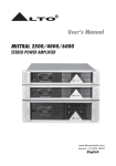
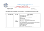
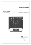
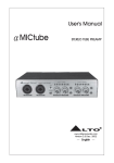
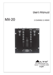
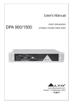
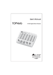
User's Manual
MX-30P
3-CHANNEL POWERED MIXER
3-CHANNEL POWERED MIXER
R
LTO
www.altoproaudio.com
Version 1.1 Septemper 2005
English
Fuse
SAFETY RELATED SYMBOLS
CAUTION
RISK OF ELECTRIC SHOCK
DO NOT OPEN
This symbol, wherever used, alerts you to the presence of un-insulated and dangerous voltages within the product enclosure. These are voltages that
may be sufficient to constitute the risk of electric
shock or death.
Protective Ground
Before turning the product ON, make sure that it is
connected to Ground. This is to prevent the risk of
electric shock.
This symbol, wherever used, alerts you to important operating and maintenance instructions.
Please read.
Never cut internal or external Ground wires. Likewise,
never remove Ground wiring from the Protective
Ground Terminal.
Protective Ground Terminal
Operating Conditions
AC mains (Alternating Current)
Always install in accordance with the manufacturer's
instructions.
Hazardous Live Terminal
ON:
To prevent fire and damage to the product, use only
the recommended fuse type as indicated in this
manual. Do not short-circuit the fuse holder. Before
replacing the fuse, make sure that the product is
OFF and disconnected from the AC outlet.
To avoid the risk of electric shock and damage, do
not subject this product to any liquid/rain or moisture.
Do not use this product when in close proximity to
water.
Denotes the product is turned on.
OFF: Denotes the product is turned off.
WARNING
Describes precautions that should be observed to
prevent the possibility of death or injury to the user.
CAUTION
Do not install this product near any direct heat source.
Do not block areas of ventilation. Failure to do so
could result in fire.
Keep product away from naked flames.
Describes precautions that should be observed to
prevent damage to the product.
Disposing of this product should not be
placed in municipal waste and should be
Separate collection.
IMPORTANT SAFETY INSTRUCTIONS
Read these instructions
Follow all instructions
Keep these instructions. Do not discard.
Heed all warnings.
WARNING
Only use attachments/accessories specified by the
manufacturer.
Power Supply
Ensure that the mains source voltage (AC outlet)
matches the voltage rating of the product. Failure
to do so could result in damage to the product and
possibly the user.
Power Cord and Plug
Do not tamper with the power cord or plug. These are
designed for your safety.
Unplug the product before electrical storms occur
and when unused for long periods of time to reduce
the risk of electric shock or fire.
Do not remove Ground connections!
External Connection
Protect the power cord and plug from any physical
stress to avoid risk of electric shock.
Always use proper ready-made insulated mains
cabling (power cord). Failure to do so could result
in shock/death or fire. If in doubt, seek advice from
a registered electrician.
Do Not Remove Any Covers
Within the product are areas where high voltages
may present. To reduce the risk of electric shock do
not remove any covers unless the AC mains power
cord is removed.
Covers should be removed by qualified service
personnel only.
No user serviceable parts inside.
1
If the plug does not fit your AC outlet seek advice from
a qualified electrician.
Do not place heavy objects on the power cord. This
could cause electric shock or fire.
Cleaning
When required, either blow off dust from the product
or use a dry cloth.
Do not use any solvents such as Benzol or Alcohol.
For safety, keep product clean and free from dust.
Servicing
Refer all servicing to qualified service personnel only.
Do not perform any servicing other than those instructions contained within the User's Manual.
PREFACE
Dear Customer:
Thank you for choosing the
endeavours.
For the
LTO MX-30P 3-Channel POWERED Mixer, which is the result of our
LTO AUDIO TEAM's
LTO AUDIO TEAM, music and audio are more than a job, it is a passion and an obsession!
We have been designing professional audio products for a long time in cooperation with some of the major brands in
the world in the audio field.
The LTO line represents unparalleled analogue and digital products made by musicians, for musicians. With our
design centres in Italy, the Netherlands, and the United Kingdom we provide you with world-class designs, while our
software development teams continue to develop an impressive range of audio specific algorithms.
By purchasing our LTO products you become the most important member of our LTO AUDIO TEAM. We would
like to share with you our passion for what we design and invite you to make suggestions, which will aid us in developing future products for you. We guarantee you our commitment for quality, continual research and development, and
of course the best prices.
The LTO MX-30P is an extremely flexible 3-Channel POWERED Mixer, configured with three input channels, which is equipped with a variety of key features including 3 phone/line inputs; 1microphone input; treble, middle and bass EQ on each
channel, crossfader curve etc..
We would like to thank all the people who made the LTO MX-30P 3-Channel POWERED Mixer possible, especially to
our designers and LTO staff. It is their passion for music and professional audio that has made it possible for us to offer
you, our most important team member, our continued support.
Thank you very much
LTO AUDIO TEAM
2
TABLE OF CONTENTS
1. INTRODUCTION.....................................................................................................................................4
2. FEATURE LIST.......................................................................................................................................4
3. CONTROL ELEMENTS..........................................................................................................................5
3.1 The Top Panel
3.1.1 The CHANNEL Section
3.1.2 The MAIN OUT Section
3.1.3 The PFL Section
3.1.4 The LEVEL METER Section
3.1.5 The CROSSFADER Section
3.2 The Front Panel
3.2.1 MIC IN Jack
3.2.2 PHONE OUT Jack
3.2.3 REVERSE Switch
3.2.4 CROSSFADER CURVE Control
3.3 The Rear Panel
3.3.1 POWER IN
3.3.2 SPEAKER OUT
3.3.3 GND Screw
3.3.4 MAIN OUT
3.3.5 EFFECTS Send and Return
3.3.6 INPUT
3.4 The Power Supply Box
3.4.1 POWER CORD
3.4.2 POWER SWITCH
3.4.3 AC FUSE HOLDER
3.4.4 DC OUTPUT
3.4.5 FAN
4. TECHNICAL SPECIFICATIONS.............................................................................................................11
5. SYSTEM BLOCK DIAGRAM.................................................................................................................12
6. WARRANTY...........................................................................................................................................13
3
1. INTRODUCTION
What a great powered mixer you have just bought. Your MX-30P is packed with features such as 3 phono inputs, 3
line inputs, 1 microphone input, 3 bands equalizer and gain control for per channel etc..
Though your MX-30P is very easy to operate, please go through this manual carefully and you will get the best out
of your MX-30P.
2. FEATURE LIST
8 Inputs: 3 phono and 3 line inputs, 1 microphone input, 1 return
Main outputs through RCA connectors, headphone output via 1/4" TRS jack
Gain control on each channel
Bass, middle, treble equalizer on each channel
PFL button
TALK control
Crossfader control
Highly accurate LEDs Meter (10-segment)
Dynamic Power:2 300W@4
Manufactured under QS9000, VDA6.1 certified management system
4
3. CONTROL ELEMENTS
3.1 The Top Panel
CHANNEL 1
MIC
PHONO
LINE
CHANNEL 2
PHONO
LINE
LINE
CHANNEL 3
R
LTO
3-CHANNEL POWERED MIXER
PHONO
LINE
LINE
MAIN OUT
LEVEL METER
MIN
GAIN
MAX
MIN
GAIN
MAX
MIN
GAIN
MAX
+10
MIN
OUT A
+7
MAX
+4
+2
+15dB
-30dB
TREBLE
+15dB
-30dB
TREBLE
-30dB
+15dB
TREBLE
0
LEFT
BAL A
-2
RIGHT
-4
-7
+15dB
-30dB
MIDDLE
+15dB
-30dB
MIDDLE
+15dB
-30dB
MIDDLE
-10
MAX
MIN
OUT B
-20
-30dB
BASS
PFL
+15dB
-30dB
BASS
+15dB
-30dB
PFL
BASS
+15dB
OFF
PFL
TALK
MAX
TALK ON
MIN
MAX
PFL
MAIN
PFL LEVEL
PFL MIX
STEREO
SPLIT
PFL MODE
300 WATT DIGITAL POWER
CH 2
CH 3
5
3.1.1 The CHANNEL Section
CHANNEL 1
-. MIC to PHONO-LINE Switch
1
The channel 1 is equipped with the MIC to PHONO-LINE
switch. This switch is used to select microphone input and
phono/line input. When it is in the right position, you can
use the PHONO/LINE switch on the rear panel to input the
line signal to the phono input connector.
1
PHONO
LINE
MIC
3
MIN
GAIN
MAX
4
-30dB
+15dB
-30dB
+15dB
TREBLE
-. PHONO-LINE to LINE Switch
2
This switch is available on input channel 2 and channel 3.
You should use the LINE position for all high level audio
signals such as CD Players, DAT, MD, etc.. You should use
the PHONO-LINE position to connect the turntables, making
sure that the PHONO-LINE switch on the rear panel is on
PHONO position. With this switch (the one on the rear panel)
on LINE position, the input channel will accept a high level
audio signal.
5
MIDDLE
6
-30dB
BASS
+15dB
8
PFL
3
-. GAIN Control
Via this knob you will adjust the input level. Do not turn this
control too much clockwise or you will overload the channel,
and do not turn it too much counterclockwise or you will
generate background hiss.
7
-. EQUALIZER Control
Each input channel is provided with 3 bands equalizer:
Treble 4 , Middle 5 and Bass 6 , and you can adjust
the gain range of each from -30dB to +15dB.
CHANNEL 2
2
PHONO
LINE
LINE
-. PROGRAM Fader
7
There is a program fader available on each input channel.
These faders are used to adjust the overall level of the input
channels.
MIN
GAIN
MAX
-30dB
+15dB
-30dB
+15dB
TREBLE
-. PFL Button
8
Engage this button to route the input signal of corresponding
channel to PFL section, and the corresponding LED illuminates.
MIDDLE
-30dB
6
BASS
+15dB
3.1.2 The MAIN OUT Section
9
-. OUT A Control
The OUT A control is used to adjust the main level of the AMP
output on rear panel.
MAIN OUT
9
MIN
OUT A
-. BAL A Control
10
The BAL A control is used to adjust the stereo balance of the
AMP output on rear panel.
MAX
10
LEFT
BAL A
RIGHT
11
OUT B
12
OFF
-. TALK Control
12
When you speak through a connected microphone, the volume
of the reproduced music will be automatically reduced by the
mixer for better intelligibility of your voice. You can determine
yourself how much the volume of the music will be reduced
via this control. You can turn off the TALK function via this
button 13 .
MAX
MIN
-. OUT B Control
11
The OUT B control is used to adjust the main level of the
BOOTH output on rear panel.
TALK
MAX
13
TALK ON
3.1.3 The PFL Section
When you connect a headphone to your MX-30P, you have
the chance of pre-listening the audio signal before the signal
reaches the main output.
-.PFL LEVEL Control
14
MIN
MAX
PFL
MAIN
PFL LEVEL
15
14
This knob will adjust the level of the headphone signal.
PFL MIX
16
STEREO
SPLIT
PFL MODE
-.PFL MIX Control
15
When set the switch mode 16 in STEREO position, you can
fade between PFL and MAIN output.
-.PFL MODE Switch
16
This is a 2-position switch. When the switch is in STEREO
position, the PFL MIX control will fade between PFL signal and
MAIN output. When the switch is in SPLIT position, the PFL
MIX control has no influence on the PFL signal.
LEVEL METER
+10
+7
+4
+2
0
3.1.4 The LEVEL METER Section
-2
-.LEVEL METER Display
17
This 10 segments LEDs Meter will indicate the output level.
-4
-7
-10
-20
7
17
3.1.5 The CROSSFADER Section
-. FADER Control
18
CH 2
Through this crossfader you can fade in between channel 2
and channel 3. The crossfader on your MX-30P is user replaceable.
CH 3
18
3.2 The Front Panel
REVERSE HOLD
SMOOTH
MIC IN
PHONE OUT
19
20
REVERSE TAP
21
SHARP
CROSSFADER
CURVE
22
3.2.1 MIC IN Jack
19
This jack will accept any unbalanced low impedance microphone. The functions of the microphone will be
controlled by the CHANNEL section on the top panel.
3.2.2 PHONE OUT Jack
20
This jack will accept a standard headphone with a 1/4" stereo plug.
3.2.3 REVERSE Switch
21
This switch will invert the direction of the crossfader so that an immediate inversion of the two channels will be
achieved. This switch has two functions: TAP and HOLD.
In TAP function the both channels will be reversed instantly and will return to their original setting as soon as
you release the switch in the center position.
In HOLD function the both channels will be locked in the reverse position. To cancel the effect you will need to
push the switch back to the center position.
3.2.4 CROSSFADER CURVE Control
22
Via this knob you will adjust the crossfader curve. When set the knob at the SHARP position, the switching
speed between CH 2 and CH 3 will be changed quite quickly by the crossfader even if you move the fader slowly;
at the smooth position, the switching speed will be changed much more slowly by the crossfader even if you
move the fader quickly.
8
3.3 The Rear Panel
25
24
25
25
CAUTION
SP
RIGHT
-
+
RISK OF ELECTRIC SHOCK
DO NOT OPEN
LEFT
-
MODEL
WARNING: SHOCK HAZARD - DO NOT OPEN
AVIS: RISQUE DE CHOC ELECTRIQUE - NE PAS OUVRIR
+
SERIAL
Apparaten skall anslutas till
jordat uttag nar den ansluts
till ett natverk
DYNAMIC POWER: 300W+300W @4
AMP
THIS CONNECTION
FOR ALTO
POWER SUPPLY ONLY!
BOOTH
GND
SEND
TAPE
FROM PFL
RETURN
TO MAIN
LINE
PHONO
GND
LINE
PHONO
GND
LINE
PHONO
L
R
MAIN OUT
INPUT 3
EFFECTS
PHONO
LINE
POWER IN
26
23
27
28
29
30
32
INPUT 2
PHONO
LINE
INPUT 1
PHONO
LINE
33 31
3.3.1 POWER IN
23
This connector is meant for the connection of MX-30P power supply box.
Note: This connection for Alto power supply only!
24
3.3.2 SPEAKER OUT
These connectors are meant for connection of the speakers. For your safety, please be careful when
connecting.
3.3.3 GND Screw
25
GND is the supplementary grounding selection for other connected instruments.
3.3.4 MAIN OUT
The AMP, BOOTH and TAPE outputs are RCA type connectors. Yes the same largely used in hi-fi and are low
impedance.
Through the AMP output 26 , you can connect your MX-30P to an amplifier, and the level will be controlled by
OUT A on top panel;
Through the BOOTH output 27 , you can connect your MX-30P to an additional amplifier and/or loudspeaker
system and the level will be controlled by OUT B on top panel;
Through the TAPE output 28 , you can connect your MX-30P to a tape recorder. The tape level is fixed, so you
should adjust the input level of the recorder.
3.3.5 EFFECTS Send and Return
You can send the PFL signal through the SEND 29 sockets to a signal processor such as reverb, equaliser,
etc.. Then from the same effect unit you bring the signal back into the MX-30P via the RETURN 30 sockets
and the audio signal is routed into the MAIN output.
9
3.3.6 INPUT
- PHONO input 31 : The three Channels feature PHONO inputs including RIIA preamplifier for the turntable.
PIN (RCA) connectors shall be used to connect the turntable.
- LINE input 32 : Through these RCA connectors you can connect a CD player, an MD player or any other
high level device such as Tape Recorder, DAT, etc..
Important Notice: If you wish to connect LINE level devices into the LINE/PHONO input, make sure that the
LINE/PHONO switch 33 is on LINE position otherwise the sensitive RIAA preamplifier built-in in the Phono
input will be overloaded and will generate distortion.
3.4 The Power Supply Box
35
36
Apparaten skall anslutas till
jordat uttag nar den ansluts
till ett natverk
FUSE:T2AL
ON
CAUTION
RISK OF ELECTRIC SHOCK
DO NOT OPEN
WARNING: SHOCK HAZARD - DO NOT OPEN
AVIS: RISQUE DE CHOC ELECTRIQUE - NE PAS OUVRIR
AC INPUT 210-240V 50Hz
POWER CONSUMPTION 400W
Apparaten skall anslutas till
jordat uttag nar den ansluts
till ett natverk
CAUTION:
OFF
REPLACE WITH THE SAME TYPE FUSE AND RATING
DISCONNECT SUPPLY CORD BEFORE CHANGING FUSE
POWER
34
37
38
MODEL
DC OUTPUT
SERIAL
3.4.1 POWER CORD
34
You can connect the plug of POWER CORD to the mains. Please check the voltage accepted by the unit
and the voltage available from your AC sockets before connecting the unit to the mains.
3.4.2 POWER SWITCH
35
This switch turns the Mixer ON and OFF. When you turn on the Mixer, the power indicator will light on.
3.4.3 AC FUSE HOLDER
36
The fuse is used to protect the AC supplies circuits of this unit. If the fuse blows, please change the fuse
with same specification. If the fuse continues to blow after replacing, please discontinue using this unit
and ask repair to the qualified technician.
Warning: Don't use wire or copper wire instead of fuse.
3.4.4 DC OUTPUT
37
You can connect the cable of DC OUTPUT to POWER IN on rear panel.
3.4.5 FAN
38
The fan can accelerate the flow of air to lower the temperature inside power supply box. The inside temperature determines the fan speed which controls the inside air flowing speed.
10
4. TECHNICAL SPECIFICATIONS
INPUTS
OUTPUTS
GENERAL
Phono Inputs 1,2 and 3
40dB gain@1kHz, unbalanced
Line Inputs 1,2 and 3
0dB gain, unbalanced
Mic Input
40dB gain, servo-balanced
Return
0dB gain, unbalanced
Headphones
typically 125mW@ 1% THD
Main Out
max +21dBu
Booth Out
max +21dBu
Tape Out
typically 0dBu
Send
typically 0dBu
Stereo Bass
+15dB/
30dB@ 50Hz
Stereo Middle
+15dB/
[email protected]
Stereo Treble
+15dB/
30dB@10KHz
Signal
>90dB(LINE)
to
Noise ratio(S/N)
70dB
Crosstalk
Distortion(THD)
0.05%
Frequency Response
20Hz
Input Gain Adjustment
POWER SUPPLY
3dB(LINE)
Connector type
20KHz (
20dB
3
2dB)
9dB (
3dB)
pole IEC, grounded
USA/Canada: 100
Main Voltage
Europe: 210
120V~, 60Hz
240V~, 50Hz
U.K./Australia: 240V~, 50Hz
Max Power Consumption
Fuse
POWER AMP SECTION
Power Amp Out
400W
100
120V~ : T4A
210
240V~ : T2AL
RMS: 2
81W@4
EIAJ: 2
158W@4
Dynamic Power: 2
PHYSICAL
300W@4
Dimension
279(L) 216(W) 102(H)mm (10.98" 8.5" 4.01")
Weight
6.7Kg
11
A
B
C
D
1
PHONO
LINE
PHONO
LINE
P
B
A
6
5
4
3
2
1
R
L
R
L
R
L
2
CHANNEL 3(INPUT)
PHONO
L INE
CHANNEL 2(INPUT)
PHONO
L INE
PHONO
LINE
PHONO
LINE
PHONO
LINE
PHONO
LINE
PHONO
LINE
PHONO
LINE
P
B
A
P
B
A
P
B
A
L EVEL M ETER
4
6
3
5
6
3
2
5
4
3
2
1
4
1
5
6
6
3
2
1
4
5
6
3
2
1
5
4
3
2
1
6
5
4
3
2
1
C
C
P
D
P
D
C
P
D
PHONE / L INE
B
A
PHONE / L INE
B
A
B
A
P
12
P
CHANNEL 1(INPUT)
PHONO
L INE
P
3
P
P
12
11
10
7
8
9
12
11
10
7
8
9
12
11
10
7
8
9
4
4
GAIN
GAIN
GAIN
GAIN
GAIN
GAIN
HI
3-BAND EQ
MI D
3-BAND EQ
LO MI D HI
3-BAND EQ
LO MI D HI
3-BAND EQ
LO MI D HI
3-BAND EQ
LO MI D HI
3-BAND EQ
LO MI D HI
LO
5
5
Volta ge Controlle d Amplifie r
2
P
1
5e
3c
4d
2b
1a
PFL M ODE
PFL LE V EL
( M A IN )
PFL M IX
(PFL )
MI C IN PU T
6
6
5e
3c
4d
2b
1a
PHONES OUT
R
L
SEN D FRO M PFL
(EFFECTS)
GAIN
7
PO WE R AMP
D 300W
PO WE R AMP
RE D
B L ACK
B L ACK
RE D
OUT
M OOTH
(M AI N OUT)
AM P
(M AI N OUT)
TYPE
(M AI N OUT)
SPEAKER
R
L
R
GAIN
GAIN
L
R
L
R
L
RETURN TO M A IN
(EFFECTS)
GAIN
D 300W
7
8
8
A
B
C
D
5. SYSTEM BLOCK DIAGRAM
6. WARRANTY
1. WARRANTY REGISTRATION CARD
To obtain Warranty Service, the buyer should first fill out and return the enclosed Warranty Registration Card within
10 days of the Purchase Date.
All the information presented in this Warranty Registration Card gives the manufacturer a better understanding of
the sales status, so as to purport a more effective and efficient after-sales warranty service.
Please fill out all the information carefully and genuinely, miswriting or absence of this card will void your warranty
service.
2. RETURN NOTICE
2.1 In case of return for any warranty service, please make sure that the product is well packed in its original shipping
carton, and it can protect your unit from any other extra damage.
2.2 Please provide a copy of your sales receipt or other proof of purchase with the returned machine, and give detail
information about your return address and contact telephone number.
2.3 A brief description of the defect will be appreciated.
2.4 Please prepay all the costs involved in the return shipping, handling and insurance.
3. TERMS AND CONDITIONS
3.1
LTO warrants that this product will be free from any defects in materials and/or workmanship for a period
of 1 year from the purchase date if you have completed the Warranty Registration Card in time.
3.2 The warranty service is only available to the original consumer, who purchased this product directly from the
retail dealer, and it can not be transferred.
3.3 During the warranty service, LTO may repair or replace this product at its own option at no charge to you for
parts or for labor in accordance with the right side of this limited warranty.
3.4 This warranty does not apply to the damages to this product that occurred as the following conditions:
Instead of operating in accordance with the user's manual thoroughly, any abuse or misuse of this product.
Normal tear and wear.
The product has been altered or modified in any way.
Damage which may have been caused either directly or indirectly by another product / force / etc.
Abnormal service or repairing by anyone other than the qualified personnel or technician.
And in such cases, all the expenses will be charged to the buyer.
3.5 In no event shall LTO be liable for any incidental or consequential damages. Some states do not allow the exclusion or limitation of incidental or consequential damages, so the above exclusion or limitation may not apply to you.
3.6 This warranty gives you the specific rights, and these rights are compatible with the state laws, you may also
have other statutory rights that may vary from state to state.
13
SEIKAKU TECHNICAL GROUP LIMITED
No. 1, Lane 17, Sec. 2, Han Shi West Road, Taichung 40151, Taiwan
http://www.altoproaudio.com Tel: 886-4-22313737
email: [email protected] Fax: 886-4-22346757
All rights reserved to ALTO. All features and content might be changed
without prior notice. Any photocopy, translation, or reproduction of part of this
manual without written permission is forbidden. Copyright c 2005 SEIKAKU GROUP
NF 02050-1.1