1
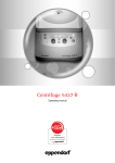
Centrifuge 5702 / Centrifuge 5702 R /
Centrifuge 5702 RH
Centrifuge 5702 / 5702 R / 5702 RH
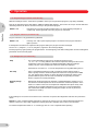
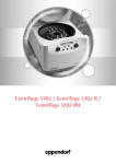
Tastenkürzel / Shortcuts
Task
Parameter change
during centrifugation
Brake
ON / OFF
Signal
ON / OFF
Parameter lock
ON / OFF
Lid
Press
short
closed
> 2 sec
short
open
Program
(only Centrifuge 5702 R / RH)
Display
flashes
5 sec
Display
flashes
5 sec
3.8
br on
br OF
br on
br OF
soft
3.12
Instruction
manual
b on
b OF
3.14
Lo on
Lo OF
3.15
> 2 sec
short + open
open
Display
5702 R /
5702 RH
> 5 sec
open
open
Display
5702
> 2 sec
1. set parameter
1
or
2
–
prog 1
prog 2
3.16
> 2 sec
At set rpm
time
open
> 2 sec
No part of this publication may be reproduced without the prior permission of the copyright owner.
Copyright© 2012 Eppendorf AG, Hamburg
2
3.13
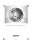
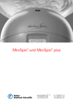
Centrifuge 5702
Abbildung 1 / Figure 1
Abb. 1 / Fig. 1
1
2
3
speed
time
stand-by
short
E
open
1
2
3
E
3
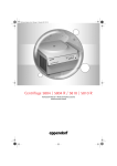
Netzschalter und -stecker
Rotormutter
Rotor
Notentriegelung
1
2
3
E
Mains switch and plug
Rotor nut
Rotor
Emergency lid release
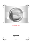
Centrifuge 5702 R
Abbildung 2 / Figure 2
Abb. 2 / Fig. 2
1
2
3
prog 1 /2
speed
temp
time
stand-by
short
C
E
open
fast temp
1
2
3
E
C
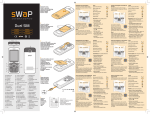
Netzschalter und -stecker
Rotormutter
Rotor
Notentriegelung
Kondenswasserschale (nur 5702 R)
1
2
3
E
C
Mains switch and plug
Rotor nut
Rotor
Emergency lid release
Condensation water tray (only 5702 R)
Front Centrifuge 5702 RH baugleich mit Centrifuge 5702 R.
Front of the Centrifuge 5702 RH is structurally identical to that of the 5702 R.
4
Contents
Contents
24
1
1.1
1.2
1.3
Introduction . . . . . . . . . . . . . . . . . . . . . . . . . . . . . . . . . . . . . . . . . . . . . . . . . . . . . . . . . . . . . . . . . . . . . . . . . . . . . .25
Intended use . . . . . . . . . . . . . . . . . . . . . . . . . . . . . . . . . . . . . . . . . . . . . . . . . . . . . . . . . . . . . . . . . . . . . . . . . . . . . .25
Delivery package . . . . . . . . . . . . . . . . . . . . . . . . . . . . . . . . . . . . . . . . . . . . . . . . . . . . . . . . . . . . . . . . . . . . . . . . . .25
Installing the device . . . . . . . . . . . . . . . . . . . . . . . . . . . . . . . . . . . . . . . . . . . . . . . . . . . . . . . . . . . . . . . . . . . . . . . .25
2
Safety precautions and applicational limitations . . . . . . . . . . . . . . . . . . . . . . . . . . . . . . . . . . . . . . . . . . . . . . . .26
3
3.1
3.2
3.3
3.4
3.5
3.6
3.7
3.8
3.9
3.10
3.11
3.12
3.13
3.14
3.15
3.16
3.17
3.18
3.19
3.20
3.21
Operation . . . . . . . . . . . . . . . . . . . . . . . . . . . . . . . . . . . . . . . . . . . . . . . . . . . . . . . . . . . . . . . . . . . . . . . . . . . . . . . .28
Functional and operator control elements . . . . . . . . . . . . . . . . . . . . . . . . . . . . . . . . . . . . . . . . . . . . . . . . . . . . . . .28
Fitting and removing the rotors . . . . . . . . . . . . . . . . . . . . . . . . . . . . . . . . . . . . . . . . . . . . . . . . . . . . . . . . . . . . . . . .28
Loading the rotors . . . . . . . . . . . . . . . . . . . . . . . . . . . . . . . . . . . . . . . . . . . . . . . . . . . . . . . . . . . . . . . . . . . . . . . . . .28
Fixed-angle rotors . . . . . . . . . . . . . . . . . . . . . . . . . . . . . . . . . . . . . . . . . . . . . . . . . . . . . . . . . . . . . . . . . . . . . . . . . .29
Swing-bucket rotors . . . . . . . . . . . . . . . . . . . . . . . . . . . . . . . . . . . . . . . . . . . . . . . . . . . . . . . . . . . . . . . . . . . . . . . . .30
Operation of round bucket with aerosol-tight caps . . . . . . . . . . . . . . . . . . . . . . . . . . . . . . . . . . . . . . . . . . . . . . . . .31
Centrifugation with timer setting . . . . . . . . . . . . . . . . . . . . . . . . . . . . . . . . . . . . . . . . . . . . . . . . . . . . . . . . . . . . . . .31
Changing the centrifugation parameters during the run . . . . . . . . . . . . . . . . . . . . . . . . . . . . . . . . . . . . . . . . . . . . .31
Short centrifugation . . . . . . . . . . . . . . . . . . . . . . . . . . . . . . . . . . . . . . . . . . . . . . . . . . . . . . . . . . . . . . . . . . . . . . . . .31
Continuous running . . . . . . . . . . . . . . . . . . . . . . . . . . . . . . . . . . . . . . . . . . . . . . . . . . . . . . . . . . . . . . . . . . . . . . . . .32
Rcf display and calculation . . . . . . . . . . . . . . . . . . . . . . . . . . . . . . . . . . . . . . . . . . . . . . . . . . . . . . . . . . . . . . . . . . .32
Adjusting the acceleration and braking ramps. . . . . . . . . . . . . . . . . . . . . . . . . . . . . . . . . . . . . . . . . . . . . . . . . . . . .33
At set rpm . . . . . . . . . . . . . . . . . . . . . . . . . . . . . . . . . . . . . . . . . . . . . . . . . . . . . . . . . . . . . . . . . . . . . . . . . . . . . . . .33
Activating and deactivating the signal tone . . . . . . . . . . . . . . . . . . . . . . . . . . . . . . . . . . . . . . . . . . . . . . . . . . . . . . .33
Parameter lock. . . . . . . . . . . . . . . . . . . . . . . . . . . . . . . . . . . . . . . . . . . . . . . . . . . . . . . . . . . . . . . . . . . . . . . . . . . . .33
Programming (for 5702 R / 5702 RH only) . . . . . . . . . . . . . . . . . . . . . . . . . . . . . . . . . . . . . . . . . . . . . . . . . . . . . . .34
Program selection (for 5702 R / 5702 RH only). . . . . . . . . . . . . . . . . . . . . . . . . . . . . . . . . . . . . . . . . . . . . . . . . . . .34
Refrigeration (for 5702 R only) . . . . . . . . . . . . . . . . . . . . . . . . . . . . . . . . . . . . . . . . . . . . . . . . . . . . . . . . . . . . . . . .34
Heating and refrigeration (only for 5702 RH). . . . . . . . . . . . . . . . . . . . . . . . . . . . . . . . . . . . . . . . . . . . . . . . . . . . . .35
Opening the centrifuge in case of power failure . . . . . . . . . . . . . . . . . . . . . . . . . . . . . . . . . . . . . . . . . . . . . . . . . . .35
Device fuses . . . . . . . . . . . . . . . . . . . . . . . . . . . . . . . . . . . . . . . . . . . . . . . . . . . . . . . . . . . . . . . . . . . . . . . . . . . . . .35
4
4.1
4.2
4.3
4.4
4.5
Maintenance and cleaning . . . . . . . . . . . . . . . . . . . . . . . . . . . . . . . . . . . . . . . . . . . . . . . . . . . . . . . . . . . . . . . . . .36
Device . . . . . . . . . . . . . . . . . . . . . . . . . . . . . . . . . . . . . . . . . . . . . . . . . . . . . . . . . . . . . . . . . . . . . . . . . . . . . . . . . . . 36
Rotors . . . . . . . . . . . . . . . . . . . . . . . . . . . . . . . . . . . . . . . . . . . . . . . . . . . . . . . . . . . . . . . . . . . . . . . . . . . . . . . . . . . 36
Refrigerated centrifuges . . . . . . . . . . . . . . . . . . . . . . . . . . . . . . . . . . . . . . . . . . . . . . . . . . . . . . . . . . . . . . . . . . . . .36
Glass breakage . . . . . . . . . . . . . . . . . . . . . . . . . . . . . . . . . . . . . . . . . . . . . . . . . . . . . . . . . . . . . . . . . . . . . . . . . . . .37
Returning devices . . . . . . . . . . . . . . . . . . . . . . . . . . . . . . . . . . . . . . . . . . . . . . . . . . . . . . . . . . . . . . . . . . . . . . . . . .37
5
Troubleshooting guide . . . . . . . . . . . . . . . . . . . . . . . . . . . . . . . . . . . . . . . . . . . . . . . . . . . . . . . . . . . . . . . . . . . . .38
6
Technical data . . . . . . . . . . . . . . . . . . . . . . . . . . . . . . . . . . . . . . . . . . . . . . . . . . . . . . . . . . . . . . . . . . . . . . . . . . . .39
7
Ordering information . . . . . . . . . . . . . . . . . . . . . . . . . . . . . . . . . . . . . . . . . . . . . . . . . . . . . . . . . . . . . . . . . . . . . .40
1 Introduction
Centrifuge 5702 is non-refrigerated, Centrifuge 5702 R is refrigerated and Centrifuge 5702 RH is a refrigerated and
heatable bench-top centrifuge. For these centrifuges following rotors are available:
with a capacity of 30 x 15 ml centrifuge tubes.
Fixed-angle rotor F-45-24-11
with a max. capacity of 24 x 1.5 / 2.0 ml in micro test tubes.
Fixed-angle rotor F-45-18-17-Cryo
with a max. capacity of 18 x cryotubes (max. 17 mm).
Swing-bucket rotor A-4-38
with a max. capacity of 4 x 85 ml in round buckets and 4 x 90 ml in
rectangular buckets.
Swing-bucket rotor A-8-17
with a max. capacity of 8 x 15 ml.
1
Introduction
Fixed-angle rotor F-35-30-17
Before using the centrifuge 5702 / 5702 R / 5702 RH for the first time, please read the operating manual.
The latest version of the manual and the safety instructions in your language can be found on the Internet at
www.eppendorf.com.
You will see this symbol on your centrifuge and at a number of points throughout this manual. The texts it
highlights are relevant to safety. Use the centrifuge only after having read the safety notices.
1.1 Intended use
The Centrifuge 5702 / 5702 R / 5702 RH is intended exclusively for indoor use and for separating aqueous solutions and
suspensions of various densities in approved test tubes.
This device may only be operated by trained specialist staff. They must have carefully read the operating manual and be
familiar with the function of the device.
1.2 Delivery package
1 Centrifuge 5702 non-refrigerated or 1 Centrifuge 5702 R refrigerated with condensation water tray or
1 Centrifuge 5702 RH refrigerated and heatable, each without rotor
1 power cable
1 operating manual
1 rotor key
1 set of fuse
1.3 Installing the device
– The device is heavy. Lifting and carrying the device can lead to back injuries.
► The device may only be transported in its original packaging.
► The device must be transported by least two people.
► Use a transport aid (e.g., dolly) to transport the device longer distances.
– For 5702 R / RH only: In order to prevent damage to the compressor following improper transport, the device
may not be switched on until four hours after setting up.
– For 5702 only: Please remove the transport safety device and keep it for possible use if the device is
subsequently moved again.
– Place the centrifuge on a solid, flat, non-resonant lab bench. For the Centrifuge 5702 R / RH , the condensation
water tray should be inserted from the side (see cover flap).
– The surrounding area must be well ventilated and protected against direct sunlight.
To ensure that the ventilation of the device is not impaired, a fundamental clearance of 30 cm to the side and a
min. of 15 cm to the back wall must be maintained. This is especially important for the refrigeration capacity of
the 5702 R / RH.
– During centrifugation, according to the recommendations set out in EN 61010-2-020 a safety clearance of 30 cm
must be maintained around the centrifuge within which there are no objects which may be destroyed and so
cause further damage.
– Only connect the device to power supplies which correspond with the electrical requirements on the name plate.
Only use sockets with a protective earth (PE) conductor and suitable power cable.
– Now connect the centrifuge to the power supply and switch it on at the main power switch (on the rear side,
see cover flap). The centrifuge is now ready for operation. The Stand-by button lights up green and the display is
active.
– Before starting, check that the rotor is firmly seated.
25
2 Safety precautions and applicational limitations
For your personal safety, please be sure to comply with the following regulations unconditionally:
Safety precautions and applicational limitations
2
26
–
The centrifuge 5702 / 5702 R / 5702 RH must only be use for the specified applications (see Introduction). It must not
be operated in explosive atmospheres. Explosive or highly reactive substances must not be centrifuged.
–
When being moved from the cool room to a normal lab environment, the centrifuge must either warm up for half an
hour in the cool room first or it must warm up for at least 3 hours in the lab before being connected to the supply
system, in order to prevent damage by condensation.
–
The centrifuge must not be moved or knocked while in operation.
–
Improperly installed or serviced centrifuges must not be operated. Repairs may only be carried out by Service
personnel authorized by Eppendorf. Use only original Eppendorf spare parts and rotors.
–
When handling toxic, radioactive liquids or pathogenic microorganisms of risk group II (see World Health
Organization: Laboratory Biosafety Manual) comply with the relevant national regulations. Bioseals are a part of
biological safety systems, which are not able to guarantee the safety of people and the environment on their own
when handling pathogenic microorganisms. When working with pathogenic organisms of a higher risk group, more
than one aerosol-tight bioseal must be provided for. If the named liquids are spilled in the rotor or rotor chamber, the
centrifuge must be thoroughly and professionally cleaned. Before using any cleaning or decontamination method
other than that set out in section 4, "Maintenance and cleaning", please consult Eppendorf to ensure the intended
method will not damage the device.
–
Rotors must always be properly secured. The centrifuge may only be operated with the rotor firmly tightened.
For mechanical stability, all the places on the rotor must be fitted with identical buckets.
–
The rotor may only be loaded symmetrically. Opposing tubes should be of the same type and be filled equally. On the
rotor you will find information concerning the weight that a completely filled bucket may not exceed.
–
Prior to centrifugation, the tubes should in any case be visually inspected for material damage. Damaged tubes may
not be centrifuged. This is because broken tubes can, in addition to sample loss, result in further damage to the
centrifuge and accessories.
–
Rotors showing clear signs of corrosion or mechanical damage must not be used. Check the accessories regularly.
–
Rotors are high-grade components which have to withstand extreme stresses and strains. Aluminum rotors are
largely protected from corrosion by the most common laboratory chemicals by means of an anodized coating, though
the protection is not unlimited. Protect the rotors from mechanical damage. Even minor scratches or cracks can
result in serious internal material damage. Avoid damaging the rotors by the use of aggressive chemicals, such as:
strong and weak alkalis, strong acids, solutions of mercury, copper and other heavy metal ions, chlorinated
hydrocarbons, concentrated salt solutions and phenol. If the rotor is contaminated by aggressive substances, clean it
immediately with a mild cleaning agent.
–
The material being centrifuged may not exceed a density of 1.2 g/ml at maximum rotation speed. If the rotor is run for
a lengthy period of time, or more often with short centrifugation runs the sample tubes will become hot. Keep within
the limits specified by the tube manufacturers.
–
Seal the tube lid down tight before centrifuging. The lids of unclosed tubes may rip off during centrifugation and
damage the centrifuge.
–
When using organic solvents (e.g. phenol, chloroform) the durability of plastic tubes may be impaired.
–
When closing the centrifuge lid do not place your fingers between the lid and the centrifuge, otherwise they may be
trapped.
2 Safety precautions and applicational limitations
The following rotors and accessory buckets have a maximum service life of 7 years:
A-4-38
5702 720.003 and 5702 740.004
A-8-17
5702 700.002
The date of manufacture is engraved on them in the format 10/01 (October 2001).
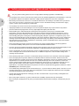
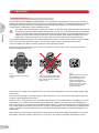
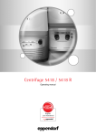
Transparent aerosol-tight caps made of polycarbonate have a maximum service life of 3 years.
The date of manufacture is embossed on them in the form of a clock
.
8 9 10
01
2
5
6
2 3 4
12
11 1
Safety precautions and applicational limitations
7
Aerosol tight caps may lose their sealing strength when exposed to organic solvents (e.g. phenol, chloroform).
Check the aerosol-tight caps regularly for changes or cracking. Aerosol-tight caps showing cracks or other changes must
be replaced immediately.
Rotors, caps or buckets which have been damaged by chemical or mechanical factors or which have passed
their maximum service life may no longer be used!
–
Transfer
If the device is passed on to someone else, please include the instruction manual.
–
Disposal
In case the product is to be disposed of, the relevant legal regulations are to be observed.
–
Information on the disposal of electrical and electronic devices in the European Community
The disposal of electrical devices is regulated within the European Community by national regulations based on EU
Directive 2002/96/EC on waste electrical and electronic equipment (WEEE).
According to these regulations, any devices supplied after 13.08.05 in the business-to-business sphere, to which this
product is assigned, may no longer be disposed of in municipal or domestic waste. They are marked with the
following symbol to indicate this.
As disposal regulations within the EU may vary from country to country, please contact your supplier if
necessary.
–
Declaration concerning the ATEX directive (94/9/EC)
The present design and ambient conditions inside Eppendorf centrifuges mean that they are not suitable for use in a
potentially explosive atmosphere. The centrifuges must therefore only be used in a safe environment such as the open
environment of a ventilated laboratory or a fully-extracted fume hood. The use of substances which may contribute to a
potentially explosive atmosphere is not permitted. The final decision on the risks in connection with the use of such
substances is the responsibility of the user of the centrifuge.
27
3 Operation
3.1 Functional and operator control elements
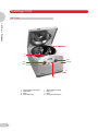
Refer to the frontal view on the first inside cover page of this manual.
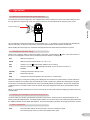
Fig. 1: Front view of the Centrifuge 5702.
Fig. 2: Front view of the Centrifuge 5702 R. Front of the Centrifuge 5702 RH is structurally identical to that of the 5702 R
Operation
3
time
–
Time dial and Start/Stop button
short
–
Short run button
speed
–
Speed selector dial and rpm/rcf button
–
Stand-by button
open
–
Lid release
1
–
Line socket with fuse set and main power switch,
device identification plate with power supply ratings
(rear).
E
–
Emergency lid release on underside with pull cord
For the Centrifuge 5702 R / 5702 RH only:
temp
–
Temperature selection buttons
fast temp
–
Controlled temperature button
prog 1
–
Program button 1
prog 2
–
Program button 2
C
–
Condensation water tray
3.2 Fitting and removing the rotors
. They indicate the direction of the
When fitting the rotor, follow the marking triangles on each side of the rotor nut
groove on the underside of the rotor, and are needed to position the rotor safely.
To insert the rotor rotate the driver pin of the motor shift longitudinally.
Fit the rotor onto the motor shaft so the marking triangles point in the same direction as the motor shaft driver pin. Tighten
the rotor nut by turning them clockwise using the rotor key supplied. If the rotor nut does not tighten easily, check whether
the rotor has caught on the motor shaft driver pin.
To release the rotor turn the rotor nut anticlockwise using the rotor key.
3.3 Loading the rotors
The rotors and buckets (round and rectangular) must be loaded symmetrically. The adapters must be loaded only with the
specified tubes. Minimize the difference in weight between the filled sample tubes. This will reduce wear on the drive and
cut running noise. The centrifuges 5702 / 5702 R / 5702 RH have an automatic imbalance detector, which shuts down the
centrifuge if the weight differences are excessive. This is indicated by the error message "Inb" in the display.
The maximum weight for a fully loaded bucket is indicated on each rotor.
28
3 Operation
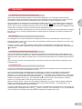
3.4 Fixed-angle rotor
The fixed-angle rotor F-35-30-17 can be loaded with 15 ml Falcons® and 15 ml round bottom centrifuge tubes. It is
available in the 10 and 30 position versions. Please use only swing-bucket rotor A-4-38 with round buckets and the
appropriate adapters for centrifuging blood sampling systems.
3
Before centrifuging the Falcons®, place their plastic adapters in the tube holders. The adapters prevent the Falcons® from
being destroyed. For the centrifugation of round bottom tubes made of Duran® glass, round rubber pads are required to
prevent the tubes from cracking. Make sure a rubber pad is placed under each glass tube before centrifuging.
Operation
In order to avoid breakage of the tubes when using centrifuge tubes of glass, polystyrene or similar materials, please
observe the limiting data with reference to endurance specified by the manufacturer.
The maximum load capacity for Falcons® is 20 x 15 ml; for 15 ml round bottom centrifuge tubes 30 x 15 ml. The rotor can
be loaded with a combination of 15 ml Falcons® and 15 ml round bottom centrifuge tubes. The maximum capacity is then
20 x 15 ml Falcons® and 10 x 15 ml round bottom centrifuge tubes.
15 ml
round bottom
centrifuge tube
15 ml Falcon®
Fig.3: Loading of rotor F-35-30-17 with 15 ml Falcons® and 15 ml round bottom centrifuge tubes
The specified max. weight of 56 g imprinted on the rotor is the gross weight rating including the tube holder,
adapter, tubes and contents. Always weigh the tube holder and the load together.
A maximum of 24 1.5/2.0 ml test tubes can be centrifuged in rotor F-45-24-11. If the appropriate adapters are used, it is
also possible to load it with 0.2 ml PCR tubes, 0.4 ml test tubes, 0.5 ml test tubes and 0.6 ml Microtainers®.
Fixed-angle rotor F-45-18-17-Cryo can be equipped with cryotubes (max. diameter 17 mm or 13 mm with adapters) and
sealable centrifuge tubes (max. diameter 16.5 mm or 12.2 mm with adapters). In each of these cases, max. tube length is
50 mm.
Maximum load (adapter, tube and contents) per bore is 3.75 g on rotor F-45-24-11 and 8.7 g on rotor F-45-18-17-Cryo.
When loading the rotors, please make sure that the tubes are inserted in the bores of the rotor opposite one another in
pairs.
To ensure that the rotor is loaded symmetrically, the tubes opposite one another need to contain approximately the same
filling quantity.
Fixed-angle rotors are operated without a rotor lid.
29
3 Operation
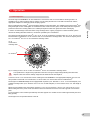
3.5 Swing-bucket rotors
The swing-bucket rotor A-4-38 can be equipped with round or rectangular buckets. Round buckets and the associated
adapters (see ordering information) are conceived for the centrifugation of Falcons®, blood withdrawal systems and other
centrifuging tubes with round bottoms. Rectangular buckets and associated adapters (see ordering information) are
conceived for the centrifugation of glass centrifugation tubes.
3
Operation
Use only the rotor / bucket (round or rectangular) / adapter combinations approved by Eppendorf. Check that all
buckets are fully attached, lubricated lightly and can swing out freely. If you use overlength tubes, it is essential to
carry out a manual swing test with empty tubes! When the rectangular buckets are not completely filled, insert the
adapters so that the bolts of the rotor A-4-38 are symmetrically loaded. Avoid unbalanced loading of the inner
adapter bores, pointing to the rotor nut, since this could cause overshooting of the rectangular buckets.
For mechanical stability, all the places must be fitted with identical buckets. The buckets are sorted by weight. The weight
class is embossed on the side of the bucket: e.g. 90 (the last 2 digits in grams). Opposing buckets must be
of the same weight class. When reordering, please quote the weight class required.
Before inserting the buckets in the grooves, make sure the grooves are clean. Dirty grooves or pegs will prevent the
buckets from swinging out evenly.
Fig. 4:
Rotor and buckets symmetrically
loaded.
Fig. 5:
Rotor and buckets asymmetrically
loaded. Not permitted, because the
pegs of the buckets are subject to
differing loads.
Fig. 6:
Adapter loaded asymmetrically.
Not permitted, because the
pegs of the bucket are not
uniformly loaded and the
loading of the adapter bores
pointing to the rotor nut could
cause overshooting of the
rectangular buckets.
The specified max. weight of 400 g imprinted on the rotor is the gross weight rating of a bucket (including adapter, tubes
and contents).
The maximum load (adapter, tubes and contents) of the round bucket is 190 g. The maximum load (adapter, tubes and
contents) of the rectangular bucket is 240 g.
A maximum of 8 x 15 ml Falcons® or 8 x 15 ml tubes of Duran® glass can be centrifuged in the rotor A-8-17. Prior to the
centrifugation of 15 ml Falcons®, please insert the provided plastic adapter into the rotor. Prior to the centrifugation of
tubes of Duran® glass, please insert the round rubber plate into the rotor. Please make certain prior to centrifugation that
such a rubber plate is found under every glass tube. In order to avoid breakage of the tubes when using centrifuge tubes
of glass, polystyrene or similar materials, please observe the limiting data with reference to endurance specified by the
manufacturer.
Only load the rotor symmetrically, so that the rotor and the pivots are evenly loaded during centrifugation. The maximum
load (adapter, tubes and contents) of the rotor A-8-17 is 8 x 38 g. The maximum permissible tube length is 120 mm.
30
3 Operation
3.6 Operation of round bucket with aerosol-tight caps
The inner part of the aerosol-tight cap is also equipped with a silicone sealing ring. Never remove this sealing ring from
the cap. Whenever using the cap, make sure that the sealing ring is undamaged and sits uniformly in the groove.
3
Silicone sealing ring
Operation
The round bucket and the aerosol-tight cap are autoclavable (121 °C, 20 minutes). The aerosol-tight cap, including the
silicone sealing ring, is subject to natural wear and must be replaced when visual inspection reveals wear.
When handling the aerosol-tight cap, remember that polycarbonate has limited chemical resistance to phenol.
3.7 Centrifugation with timer setting
Switch on the centrifuge, with the mains power switch if necessary, and then with the
switch. The nominal values of
the last run are displayed. Load the rotor symmetrically and close down the centrifuge lid.
time
–
Alters the running time.
speed
–
Alters the speed in increments of 100 1/min or rcf.
start
–
Starts the run. The
stop
–
Stops the centrifuge. The
standstill.
stand-by
–
Centrifuge switched to stand-by mode.
open
–
Releases the lid latch.
temp
–
Changes the nominal temperature value (for 5702 R / 5702 RH only)
symbol flashes while the rotor is running.
symbol appears briefly as soon as the rotor comes to a
While the centrifuge is running the remaining time is displayed. The last minute is counted down in seconds. When the
preset time elapses the centrifuge stops automatically and emits a signal tone to indicate the centrifugation is finished.
The lid of the non-refrigerated Centrifuge 5702 opens automatically following centrifugation. The lid of the refrigerated
Centrifuge 5702 R / 5702 RH remains closed to maintain the sample temperature and can be opened with the OPEN
button.
When you switch off the centrifuge 5702 / 5702 R / 5702 RH at the main power switch the display goes blank after a few
seconds' delay.
3.8 Changing the centrifugation parameters during the run
The timer setting, the rotation speed and the temperature (only 5702 R / 5702 RH) can be changed during the run by
briefly pressing the SHORT button. The display begins flashing. You can then set the new centrifugation parameters with
the TIME and SPEED and the TEMP dial adjustors. The new centrifugation parameters are programmed after 5 seconds.
3.9 Short centrifugation
short
–
Press this button with the lid closed to start a short run at maximum speed.
The centrifuge stops when you release the SHORT button again.
31
3 Operation
3.10 Continuous running
3
time
–
The continuous run function is set by turning the TIME dial to either above
99 minutes or below 0.5 minutes. The timer displays "oo" to indicate that continuous
running is active. The time is counted upward in minutes.
stop
–
Ends continuous running
Operation
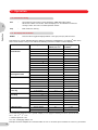
3.11 Rcf display and calculation
SPEED
–
Press the dial to toggle the display between 1/min (rpm) and (rcf) and vice versa.
Note that the rcf (g-force) indicated when the display is switched is standardized to 15 ml Falcon® tubes in the
rotor A-4-38. At 4,400 1/min you can achieve the following maximum rcf with the various adapters.
Max. centrifuging
radius (cm) rmax
Max. rcf (g-force),
rounded
Rotor
Adapter
A-4-38
Round bucket
1.5/2.0 ml
13.4
2,900
1.1 – 1.4 ml
13.2
2,850
2
– 7 ml
13.2
2,850
2.6 – 7 ml
13.2
2,850
4
– 10 ml
13.2
2,850
9
– 15 ml
13.0
2,800
15 ml Falcon
13.7
3,000
25 ml
13.5
2,900
50 ml Falcon
13.5
2,900
85 ml
13.5
2,900
5 – 7 ml
12.7
2,750
9 ml
12.7
2,750
15 ml
12.7
2,750
20 ml
12.7
2,750
®
®
A-4-38
Rectangular bucket
25 ml
12.7
2,750
15 ml Falcon®
12.8
2,770
15 ml DIN-tube
12.8
2,770
F-35-30-17
Outer ring
15 ml
12.7
2,750
12.7
2,750
F-35-30-17
Inner Ring
15 ml
10.7
2,300
10.7
2,300
F-45-24-11
0.2 ml
6.6
1,430
0.4 ml
8.2
1,770
0.5/0.6 ml
7.4
1,600
1.5/2.0 ml
8.2
1,770
without adapter
9.1
1,970
with adapter
8.9
1,930
A-8-17
F-45-18-17-Cryo
15 ml Falcon
®
®
15 ml Falcon
To ascertain the maximum rcf for a specific adapter you can apply the following formula as per DIN 58 970:
rcf = 1,118 · 10–5 · n2 · rmax
n: rotational speed in 1/min
rmax: max. centrifuging radius in cm
Example: The 85 ml adapter has a maximum radius of 13.5 cm. At 4,000 rpm a maximum rcf of 2,415 x g is reached.
32
3 Operation
3.12 Adjusting the acceleration and braking ramps
When working with Ficoll® density gradients or other sensitive applications (e.g. certain types of blood and urine
centrifugations) slower acceleration and braking ramps can be switched on for the Centrifuge 5702 / 5702 R / 5702 RH.
This makes the centrifuge accelerate and decelerate gently. This guarantees optimal centrifugation results.
3
Press the SHORT key for longer than 5 seconds while the centrifuge lid is open. On the Centrifuge 5702, the text in the
display changes from "br on" (brake on) to "br OF" (brake off). The symbol soft appears in the display of Centrifuges
5702 R / RH. The slower acceleration and braking ramps are now activated. The current status will be displayed when the
SHORT button is pressed for less than 5 seconds while the centrifuge lid is open.
Operation
To switch faster acceleration and braking back on, press the short key for longer than 5 seconds again while the centrifuge
lid is open. The "br on" message appearing briefly in the display signals the reactivation of the faster acceleration and
braking ramps.
3.13 At set rpm
For centrifugation, time can be counted either immediately from the start or not until attainment of the preset speed.
Pressing the START / STOP button for longer than 2 seconds with the centrifuge lid open switches the "at set rpm" mode,
symbolized by the pictogram
.
To exit the "at set rpm" mode again and begin counting down the centrifugation time immediately after starting the
centrifuge, press the START / STOP button again for longer than 2 seconds with the centrifuge lid open until the pictogram
is displayed.
3.14 Activating and deactivating the signal tone
Press and hold down the OPEN button for longer than 2 seconds with the centrifuge lid open to toggle between "b on"
(signal tone on) and "b OF" (signal tone off). Press the OPEN button for less than 2 seconds with the centrifuge lid open to
display the current status. With the Centrifuge 5702 R / 5702 RH the selected signal tone is symbolized by the pictogram
.
The current status is shown when the OPEN button is pressed for less than 2 seconds while the centrifuge lid is open
(Centrifuge 5702).
3.15 Parameter lock
To secure the centrifuge parameters against unintentional adjustment, the Centrifuge 5702 and the Centrifuge 5702 R /
5702 RH allows you to lock in the parameters you need.
Press and hold down OPEN- and SHORT-button simultaneously for at least 5 seconds with the centrifuge lid open.
After 5 seconds the dial adjuster is disabled and the centrifugation parameters are locked against unintentional
adjustment. "Lo on" appears in the display of the Centrifuge 5702. In the display of the Centrifuge 5702 R / 5702 RH the
locked parameters are symbolized by an additional pictogram
. The preset parameters can then no longer be altered,
whether the centrifuge is running or not. The START/STOP button can still be used to start and stop the centrifuge
however. It is also still possible to switch the signal tone and rcf switch on and off.
With the Centrifuge 5702 R / 5702 RH it is also possible to additionally lock a program called up against unintentional
resetting. A program already written is called up through the program buttons and then – as described above – the
program buttons and dial adjustor setting deactivated.
To enable the dial adjuster again, press and hold down OPEN- and SHORT-button simultaneously for 5 seconds with the
centrifuge lid open. The display shows "Lo OF" or
(5702 R / 5702 RH ). The current status ("Lo on") can be displayed
on the Centrifuge 5702 by briefly pressing the SHORT and OPEN buttons while the lid is open.
33
3 Operation
3.16 Programming (for 5702 R / 5702 RH only)
With the Centrifuge 5702 R / 5702 RH it is possible to store up to two permanent programs (only during standstill):
First set the required program data with the TIME and SPEED dial adjustors. The function "at set rpm" and the switchedoff braking function can also be stored if necessary in the permanent program.
3
PROG 1 or 2
Hold down for 2 seconds until the program button is no longer flashing and lights up
continuously. A brief signal will sound. The program is now stored.
–
Operation
3.17 Program selection (for 5702 R only)
Program selection is only possible during stillstand.
PROG 1 or 2
Pressing once calls up the required program. The button for the program activated
lights up in blue.
–
If dial adjustors or buttons are required for the program setting, the program remains unchanged.
The text "Pr 1" (Program 1) or "Pr 2" (Program 2) appears in the centrifuge display.
Exit the program by again pressing the program button. The blue lighting of the button extinguishes and the centrifugation
parameters can be set freely again.
3.18 Refrigeration (for 5702 R only)
temp
–
The nominal temperature value can be set with the arrow keys from
– 9 °C to + 40 °C. During stillstand, the nominal temperature setting and the current
temperature in the rotor chamber are displayed alternately. With the centrifuge
running, only the current temperature in the rotor chamber is displayed.
A deviation of more than ± 3 °C from the temperature set is signalled during the run.
fast temp
–
starts a controlled temperature run with a centrifuge-specific rotation speed, in
order to quickly reach the selected temperature in the rotor. During the FAST TEMP
run, "FA" appears in the display, as well as the present temperature and the fixed
optimal rotational speed. The run ends automatically or by pressing the STOP
button. A signal tone sounds periodically.
Stand-by refrigeration
–
With closed centrifuge lid the rotor chamber is refrigerated before and after a run to
the selected nominal temperature if this is less than the ambient temperature. Since
there is no rotation of the rotor, the temperature adaptation takes place slowly. If the
centrifuge was in standby refrigeration over a longer time or at low temperatures,
start a brief FAST TEMP run before inserting the samples in order to prevent the
samples from freezing.
If the centrifuge is not used for more than 8 hours or the lid is not opened, the refrigeration switches off to protect the
device.
Remark: In cases of higher ambient temperature, temporary air noises may occur until the desired temperature is
attained. These are a sign of high refrigeration capacity. Block the ventilation slots under no circumstances!
For ambient temperatures below 18 °C a warming-up time of 1 hour is required before operating.
34
3 Operation
3.19 Heating and refrigeration (5702 RH)
In the case of the Centrifuge 5702 RH, we are dealing with a benchtop centrifuge with a regulated heating and cooling
system. The Centrifuge 5702 RH can be refrigerated or heated precisely within a temperature range from – 9 °C to
+ 42 °C. By way of preprogrammed temperature profiles, it is possible to set optimized temperature arcs for the available
swing-bucket and fixed angle rotors. This enables exact temperature control even for sensitive samples.
3
Display
Rotor
ro F 35
Fixed-angle rotor F-35-30-17
ro F 24
Fixed-angle rotor F-45-24-11
ro F 18
Fixed-angle rotor F-45-18-17-Cryo
ro A4 rE
Swing-bucket rotor A-4-38 with rectangular buckets
ro A4 ro
Swing-bucket rotor A-4-38 with round buckets
ro A8
Swing-bucket rotor A-8-17
ro AL L
General temperature profile for all rotors
Operation
Setting the preprogrammed temperature profiles:
Pressing the Fast Temp key while the centrifuge lid is open results in the display of the set rotor with the corresponding
temperature profile. Using the arrow keys it is possible to select other temperature profiles. The displays appearing stand
respectively for the following rotors:
After 5 seconds a selected temperature profile will be automatically adopted and the display will return to the
operating status.
temp
–
The temperature nominal value can be set using the arrow keys. During the rest
period of the centrifuge, the current temperature and the temperature nominal value
are displayed alternately (current temperature short, temperature nominal value
long). Only the current temperature is displayed during the run. A deviation of the set
temperature nominal value of more than ± 3 °C is signalled during the run by a
blinking temperature display
fast temp
–
Starts a temperature control run in order to reach the preselected temperature as
quickly as possible. During the temperature control run, "FA" appears in the display,
as well as the current temperature and the optimum rotational speed. Refrigeration
runs at less than room temperature are automatically carried out with a rotorspecific, low rotational speed, while heating runs are carried out initially with a
maximum and then with a nominal rotational speed. For runs with precisely
controlled temperatures, we recommend starting a short Fast Temp run immediately
prior to centrifugation. This prevents an overshooting of the temperature in the rotor
chamber, such as can sometimes occur after longer standby periods.
Stand-by
Heating and
refrigeration
–
The rotor chamber is heated or cooled to the selected nominal temperature both
before and after a run with the lid closed. Because the rotor does not thereby rotate,
the temperature adjustment occurs slowly. The current temperature in the rotor
chamber is displayed. For runs with precise temperature control following longer
standby periods, we recommend starting a brief Fast Temp run immediately prior to
centrifugation. This prevents potential overshooting of the temperature in the rotor
chamber.
3.20 Opening the centrifuge in case of power failure
Pull the power plug and wait for the rotor to come to a stop (this may take as long as 5 minutes!). Emergency lid release
on underside of device by pull cord: In front of the front right suction foot there is a small white plastic cap in the base
plate (see "E" in figures 1 and 2, cover flap). Remove the cap and draw the cord out straight downward.
Please be sure to later make certain that the cord is pushed back completely into the housing before closing the lid.
Press the plastic button into the baseplate again.
3.21 Device fuses
The fuse box is located under the main power plug. The fuse box can be removed from the rear. The two fuses can be
replaced (see Ordering information).
35
4 Maintenance and cleaning
4.1 Device
The outer surfaces of the centrifuge and the rotor chamber should be cleaned regularly with a mild cleaning agent. This is
for hygiene purposes and to prevent adhering impurities causing corrosion.
If material hazardous to health or aggressive material contaminate the device, the owner is responsible for appropriate
cleaning and decontamination.
Before cleaning, unplug the power plug with the lid open, unscrew the rotor using the rotor key supplied and clean it
separately. Use a mild cleaning agent for cleaning the accessible surfaces of the device. Choose disinfection methods that
correspond to the current legal regulations and guidelines for your area of application. Use, for example, alcohol (ethanol,
isopropanol) or alcohol-based disinfectants.
Do not allow any liquid to get into the gap at the motor shaft outlet. For this reason, the rotor chamber should be cleaned
only with a damp cloth.
Maintenance and cleaning
4
You should also consult your laboratory safety officer with regard to a suitable method of cleaning and disinfecting. Before
any cleaning or disinfecting method other than that recommended by the manufacturer is used, please check with
Eppendorf that the intended method will not damage the device or its accessories. In order to ensure long-term, reliable
work with your centrifuge, please note that aggressive chemicals may damage the rotor and the chamber. Check your
device once a month for corrosion and damage.
The rubber seals in the rotor chamber should be rinsed off thoroughly with water and lubricated with glycerin or talc after
every clean to prevent them becoming brittle.
4.2 Rotors
The rotors, buckets, tube holders and adapters should be cleaned once a month or when necessary with a neutral
cleaning agent to prevent residues of the material being centrifuged from changing the properties of the centrifuge and its
accessories. The rotor must be taken off for this.
Never place components in disinfectants or cleaning agents which contain sodium hypochlorite/chlorine or are oxidants.
This will cause the material to change. Disinfection with glutaraldehyde solution is possible. We recommend Cidex®
activated glutaraldehyde solution. The plastic adapters and rubber plates are dishwasher safe.
Check the tube holders and buckets for residues and corrosion. For thorough cleaning, remove the rubber plates from tube
holders and buckets and clean all parts separately.
Then refit the rotor and bolt it into place with the supplied rotor key. Check the rotor, tube holders and buckets once a
month for mechanical damage.
All rotors, buckets, adapters, caps and tube holders can be autoclaved (121 °C, 20 min).
The aerosol-tight cap, including silicon sealing ring, rubber mats and rectangular bucket adapters are subject to normal
wear and must be replaced when a visual inspection reveals wear.
Do not unbolt the rectangular bucket adapters from each other.
On the swing-bucket rotor make sure, in particular, that the pegs and grooves of the buckets are free of dirt. They should
be lightly lubricated with pivot grease (provided with each swing-bucket rotor) so the buckets can swing freely.
The aerosol-tight buckets must not be stored with their caps sealed!
4.3 Refrigerated centrifuges
Clean condensation water and ice buildup regularly from the rotor chamber (by defrosting), using a soft, absorbent towel.
Regularly empty and clean the condensation water collector. Remove this from the left. Please clean the condensation
water drain regularly.
36
4 Maintenance and cleaning
4.4 Glass breakage
When centrifuging glass tubes, please observe that high speeds/rcf’s increase the risk of glass breakage. Please follow
the manufacturer’s instructions concerning the maximum speed/rcf of centrifuge tubes. In the event of glass breakage,
carefully remove all splinters and all ground glass from the rotor, the buckets, the adapters and the rotor chamber. You
may need to replace the rubber mats and adapters to prevent further damage.
4
Fine splinters of glass may otherwise scratch the surface of the rotors and buckets, reducing their resistance to
chemicals. The air turbulences within the rotor chamber produce a very fine black powder of abraded metal. In addition
to causing damage to the rotor chamber, rotor, buckets and adapters, the powder also contaminates the samples.
Maintenance and cleaning
Check the rotor bores regularly for residues and damage.
4.5 Returning devices
When returning centrifuges, please ensure that these devices are fully decontaminated so that they do not present a
health risk to our service staff.
You will find additional information and a blank of the decontamination confirmation at www.eppendorf.com.
Do also consult your laboratory safety officer about a suitable decontamination method.
Please fill out the decontamination confirmation and place it together with the device when it is to be sent back to
Eppendorf.
37
5 Troubleshooting
Error
Cause
Remedy
Stand-by button lit red.
Centrifuge not ready.
Press STANDBY button.
No display.
No power.
Plug power cable in on both ends.
Power failure.
Check power fusing of lab / device.
Power failure.
Emergency lid release (see section 3.20).
Rotor still running.
Wait for rotor to stop.
Centrifuge shakes
when starting up.
Rotor unevenly loaded.
Stop centrifuge and load evenly.
Centrifuge will not start.
Lid not closed.
Press lid down or press OPEN button.
Display:
Lid not released.
Press lid down tight, press Start/Stop or emergency lid
release.
Lid not locked.
Close lid again.
Lo on
(only 5702)
Centrifugation parameters
locked against adjustment.
With open centrifuge lid simultaneously press SHORT
and OPEN for 5 seconds (see 3.15) if parameters
should be readjusted.
P1
P2
Program 1 or 2 is called up.
Press illuminated program button to exit the program
level (if required).
FA
Display indicates a FAST TEMP
run.
The run can be interrupted with the START / STOP
button if required.
Inb
Rotor unevenly
loaded.
Check loading and repeat run.
Int
Power failure during run.
Check power plug. Wait for rotor to come to a stop.
Repeat run.
Er 2
Unbalanced rotor switch
defective.
Inform Service.
Er 3
Error in speed system.
Leave device switched on until error message
disappears (up to 5 min).
Er 5
Lid switch.
Close lid, restart.
Er 6
Drive error.
Repeat run.
Er 7
Overspeed.
Error in drive or speed measurement system.
Er 8
Drive error.
Repeat run.
Er 9 – 25
Electronics error.
Repeat run.
Er 18
Temperature deviation
> 5 °C fr. nominal value.
Nominal value setting too low or refrigeration defective.
Er 19
Refrigeration unit overheated.
Make sure that the air circulation through the cooling
slots is not impaired.
Er 23
(only 5702)
Motor overheating.
Allow motor to cool.
Er 24
Fault in the refrigeration unit.
At start of operation: contact Service. After longer
running time: allow centrifuge to cool down.
5
Troubleshooting
Lid will not open.
LID
If the suggested remedy repeatedly fails, please contact Service.
38
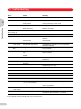
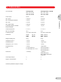
6 Technical data
Centrifuge 5702
230 V / 50 – 60 Hz
120 V / 50 – 60 Hz
100 V / 50 – 60 Hz
Centrifuge 5702 R / 5702 RH
230 V / 50 – 60 Hz
120 V / 50 – 60 Hz
100 V / 50 – 60 Hz
Power output:
200 W
380 W
Max. speed:
4 400 rpm
4 400 rpm
Max. centrifugal acceleration:
3 000 rcf
3 000 rcf
Max. load:
4 x 90 ml
4 x 90 ml
Max. kinetic energy:
2 280 Nm
2 280 Nm
Permissible density of material
being centrifuged:
1,2 g/ml
1,2 g/ml
Ambient temperature:
2 – 40 °C
10 – 40 °C
Max. rel. air humidity:
75 %
75 %
Positioning height:
max. 2000 m above NSL
max. 2000 m above NSL
Dimensions:
Height:
Depth:
Width:
Height: 265 mm
Depth: 580 mm
Width: 380 mm
Weight excluding rotor:
20 kg
36 kg
Startup time (230 V):
< 25 sec
< 25 sec
Deceleration time:
< 25 sec
< app. 25 sec
Startup time (100 V / 120 V):
< 25 sec
< 25 sec
Deceleration time:
< 25 sec
< app. 25 sec
Fuses:
2.5 A time-lag 230 V
5.0 A time-lag 120 V / 100 V
2.5 A time-lag 230 V
5.0 A time-lag 120 V
6.0 A time-lag 100 V
Noise level:
< 58 dB (A)
< 54 dB (A),
steady state at 4ºC;
23ºC ambient temperature,
empty rotor
Overvoltage category:
II
II
Degree of contamination:
2
2
241 mm
395 mm
320 mm
6
Technical data
Line connection:
Technical specifications subject to change!
39
7 Ordering information
7
Centrifuge 5702
230 V / 50 – 60 Hz, without rotor
5702 000.019
Centrifuge 5702 R
230 V / 50 – 60 Hz, without rotor
5703 000.012
Centrifuge 5702 RH
230 V / 50 – 60 Hz, without rotor
5704 000.016
Ordering information
Fixed-angle rotor and accessories
Fixed-angle rotor F-35-30-17
Aluminum, 30 places, angle 35°,
for mounting of 15 ml Falcons® or
15 ml round bottom centrifuge tubes,
complete with stainless steel tube holders for
30 places
10 places
5702 704.008
5702 705.004
Tube holders (stainless steel), for rotor F-35-30-17,
for mounting of 15 ml Falcons® or
15 ml round bottom centrifuge tubes, set of 10
5702 707.007
Adapter, conical, to support 15 ml
for rotor F-35-30-17, set of 10
Falcons®,
5702 706.000
Rubber mat for 15 ml round bottom centrifuge tubes, set of 10
5702 708.003
Fixed-angle rotor F-45-24-11
Aluminum, angle 45°, 24 places, max. 11 mm
for mounting of 1.5/2.0 ml micro test tubes
5702 746.002
Adapter for 0.2 ml PCR tubes,
for rotor F-45-24-11, set of 6
5425 715.005
Adapter for 0.4 ml micro test tubes,
for rotor F-45-24-11, set of 6
5425 717.008
Adapter for 0,5 ml micro test tubes and
0.6 ml Microtainer®, for rotor F-45-24-11, set of 6
5425 716.001
Fixed-angle rotor F-45-18-17-Cryo
Aluminum, angle 45°, 18 places, max. 17 mm
for mounting of cryotubes (max. 17 mm) and
centrifuge tubes which can be sealed (max. 16.5 mm),
max. length in mm: 50
5702 747.009
Adapter for cryotubes (max. 13 mm) and
centrifuge tubes which can be sealed (max. 12.2 mm),
max. length in mm: 50
5702 752.002
Swing-bucket rotors and accessories
40
Swing-bucket rotor 4 x 85 ml, type A-4-38,
aluminum, incl. 4 round buckets
5702 720.003
Swing-bucket rotor 4 x 85 ml, type A-4-38,
aluminum, excluding round buckets
5702 740.004
Round bucket 85 ml for A-4-38, set of 4
Round bucket 85 ml for A-4-38, set of 2
5702 722.006
5702 761.001
Caps, aerosol tight, for round bucket 85 ml, set of 2
5702 721.000
7 Ordering information
Adapter for standard tubes and blood sampling systems for round bucket 85 ml
5702 745.006
5702 736.007
5702 737.003
5702 719.005
5702 735.000
5702 724.009
5702 732.001
5702 723.002
5702 717.002
5702 734.004
5702 718.009
Rectangular bucket 90 ml for A-4-38, set of 4
Rectangular bucket 90 ml for A-4-38, set of 2
5702 709.000
5702 762.008
7
Ordering information
2 adapters 4 x 1.5 – 2.0 ml micro test tubes
2 adapters 5 x 1.1 – 1.4 ml (ø adapter bore x max. vessel length in mm: 8.5 x 100)
2 adapters 5 x 2 – 7 ml
(12.5 x 100)
2 adapters 4 x 2.6 – 7 ml
(13.5 x 100)
4 adapters 4 x 4 – 10 ml
(16 x 100)
9 adapters 4 x 9 – 15 ml
(17.5 x 100)
(17.2 x 121)
2 adapters 1 x 15 ml Falcon®
2 adapters 2 x 15 ml Falcon® *
(17.2 x 121)
2 adapters 1 x 25 ml
(25 x 100)
(30 x 115)
2 adapters 1 x 50 ml Falcon®
2 adapters 1 x 85 ml
(38 x 106)
* Do not use with aerosol tight caps.
Adapter for standard tubes for rectangular buckets
2 adapters 10 x 5 – 7 ml
2 adapters 8 x 9 ml
2 adapters 6 x 15 ml
2 adapters 4 x 20 ml
2 adapters 2 x 25 ml
5702 710.008
5702 711.004
5702 712.000
5702 713.007
5702 716.006
Swing-bucket rotor type A-8-17
5702 700.002
Adapter, conical, to support 15 ml Falcons®,
for rotor A-8-17, set of 8
5702 702.005
Rubber pad for 15 ml round bottom centrifuge tubes, set of 8
5702 701.009
Set of fuses
for 5702 / 5702 R 230 V (2 x 2.5 A time-lag)
for 5702 / 5702 R 120 V (2 x 5 A time-lag)
5425 351.003
5425 353.006
Important note:
Please use the original accessories recommended by Eppendorf. Using spare parts or disposables which we have not
recommended can reduce the precision, accuracy and life of the centrifuges. We do not honor any warranty or accept
any responsibility for damage resulting from such action.
Falcon®:
Cidex®:
Duran®:
Ficoll®:
Microtainer®:
Registered trademark of Becton Dickinson
Registered trademark of Johnson & Johnson
Registered trademark of Schott
Registered trademark of Pharmacia Biotech AB
Registered trademark of Becton Dickinson
Rotor code
All Eppendorf rotors are designated
according to a simple, logical system
which describes the technical specifications as a uniform series of numbers
and letters e.g.:
Fixed-angle
rotor
Angle of
adapter bore
F A
Aerosol-tight
version
45
∅ Tube/
Adapter
30
Max. no. tubes/
adapters
11
∅ tube/adapter
bore
Swing-bucket rotor
A
4
81
Max. no tubes/
adapters
41
eppendorf® is a registered trademark.
5702 901.016-10/052012 · Printed in Germany · Printed on chlorine-free bleached paper
Your local distributor: www.eppendorf.com/worldwide
Eppendorf AG · 22331 Hamburg · Germany · Tel: +49 40 53801-0 · Fax: +49 40 538 01-556 · E-mail: [email protected]
Eppendorf North America, Inc. · 102 Motor Parkway · Hauppauge, N.Y. 11788-5178 · USA
Tel: +1 516 334 7500 · Toll free phone: +1 800-645-3050 · Fax: +1 516 334 7506 · E-mail: [email protected]
Application Support Europe: Tel: +49 1803 666 789 (Preis je nach Tarif im Ausland; 9 ct/min aus dem dt. Festnetz; Mobilfunkhöchstpreis 42 ct/min)
[email protected]
North America: Tel: +1 800 645 3050 · E-mail: [email protected]
Asia Pacific: Tel: +60 3 8023 6869 · E-mail: [email protected]