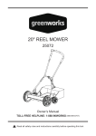
Download Owner`s Manual
Transcript
-2-
Note:
• Carefully remove the parts from the box.
• Inspect the parts carefully in order to verify that no breakage or
damage occurred during shipping.
• Do not discard the packing material until all parts have been
examined.
• If any parts are damaged or missing, call 888-896-6881 for
assistance.
PACKING LIST
1 Top Handle
2 Centre Handle pieces
2 Lower Handle pieces
8 Knobs, 8 Bolts, 8 Washers
2 C-clips
1 Reel Mower Body
UNPACKING
Cutting Path........................................................20" (50.8 cm)
Height Adjustments.........................1 3/4 - 2 3/4" (4.5 - 7 cm)
Wheels...............................................6" (15 cm) rear wheels,
10" (25 cm) front wheels
Weight...........................................................27 lbs (12.35 kg)
TECHNICAL DATA
-3-
• Never place hands, fingers, or feet inside the reel. Although
this mower is not powered by a motor, the reel spins when the
wheels turn, and it is sharp enough to cause serious injury.
• Never mow the grass when it is wet enough to be slippery.
• Do not use the reel mower while barefoot or while wearing sandals.
• Walk slowly. Do not run. Always make sure of your footing when
using the reel mower.
• Do not intentionally strike or ram trees, fences, etc. Doing so
may cause injury or may severely damage the reel mower
mechanisms.
• Verify that the reel mower is in proper operating condition. Do not
attempt to operate the reel mower if it is damaged. Have it repaired
before using.
SAFETY RULES
ASSEMBLING THE HANDLE
IMPORTANT! Some of the following symbols may appear on
this tool. Study them carefully and learn their meaning.
Proper interpretation of these symbols will allow for better and
safer operation of the tool.
1.
2.
3.
4.
5.
6.
7.
8.
9.
Top handle
Center handle pieces
Left lower handle
Right lower handle
Foam grip
Long bolts
Flat washer
C-clip
Knob
Tools Required
Pliers (Not included)
NOTE: Do not tighten the
bolts completely until all
bolts have been inserted
through the holes in the
handle pieces.
3
6
1
-4-
2
8
9
6
9
4
Fig 1
7
6
14
ASSEMBLY INSTRUCTIONS Refer to Fig 1.
This product normally requires 6 to 10 minutes for assembly.
1. Insert the 2 center handle pieces into the left and right sides of
the top handle, and secure them in place using screws.
2. Connect the right lower handle to the left lower handle, and
secure using two 1 3/8” long bolts and hex nuts (provided).
3. Attach the top handle assembly to the lower handle assembly
using four 1 3/8” long bolts and hex nuts (provided).
4. Tighten all of the hex nuts on the joints of the handle assembly.
ASSEMBLY
SAFETY RULES
-5-
1.The cutting height of the 20”
(50.8 cm) Reel Mower can be
adjusted from 1 3/4 to 2 3/4”
1
(4.5 to 7 cm) by moving the height
adjusment levers (1) to the
desired position. The height
adjusment levers are located
next to the smaller wheels.
Fig.3
2. In order to set the mower to its
lowest cutting position, pull the height adjustment levers (1) on both
sides to their highest positions.
3. In order to set the mower to its highest cutting position, move the
adjustment levers (1) on both sides to their lowest positions.
Note: The two height adjustors MUST be set to the same position (height).
4. The mower can be set to other cutting heights by moving the adjustors to
any position within their range.
CUTTING HEIGHT ADJUSTMENTS
OPERATION
NOTE: It may be necessary to use the pliers in order to grip the
C-clips properly and to apply the required pressure.
1. After assembling the handle,
Front Mower
line up the holes at the lower
end of each handle arm with
the short posts that extend out
from the side plates of the
1
mower base.
2. Insert the posts into the holes
2
at the end of the handle arms, Fig.2
and then snap the C-clips (1) onto the slotted posts (2) on both sides,
in order to prevent the handle from coming off.
ATTACHING THE HANDLE TO THE MOWER BASE
ASSEMBLY
-6-
Do not over-tighten the cutting bar, because doing so could damage the
cutting bar and the blades.
WARNING
Fig.5
• Vibrations during shipping can cause misalignment, which often causes
the blades to become too loose or too tight. This will result in a rough,
uneven cut, or the mower will be hard to push.
1. Each end of the cutting bar can
be adjusted separately.
2. The cutting bar blade, which is
located under the reel, is able to
pivot. The two adjustment nuts
(2) located at the back of the
mower move the cutting bar
away from the blades when they
1
are turned counter-clockwise,
Fig.4
and closer to the blades when
they are turned clockwise.
3. The upper locking nut (1) that is
2
located between the front and
rear radial wheels must be
loosened before the cutting bar
can be adjusted.
NOTE: The blades were pre-adjusted prior to leaving the factory, but
it is recommended that the adjustment be verified prior to the first use.
ADJUSTING THE MOWER BLADE
ASSEMBLY
-7-
NOTE: Use a 10 MM socket or wrench to adjust the cutting bar. Use an
industrial or valve lapping compound of between 100 and 240 grit on the
blades in order to ensure that all traces of compound are removed.
Lubricate the axle and pinion with a light film of wheel bearing grease.
CHECKING THE ADJUSTMENTS
1. Turn mower upside-down.
2. Insert a piece of paper between the cutter bar and the reel blades,
and carefully turn the reel wheels by hand.
3. All of the blades should slice the paper evenly, along the entire length
of the cutter bar, while the reel turns smoothly.
4. If the mower produces an intermittent cut, the appropriate side of the
blades should be adjusted in order to achieve the proper cutting action.
GENERAL CARE
1. A minimal amount of care is required in order to ensure the smooth
operation of the mower.
2. In order to avoid damage to the mower or to the cutting blades, keep
the area to be mowed free of any debris.
3. For best results, regularly apply oil or lubricant to the mower’s cutting
surfaces, cutting reel axle shaft, and wheels.
WARNING: Clean any grinding compound or debris from the cutting bar
blade, reel blade, pinions, and pawls.
TIGHTENING THE BLADES
The cutter bar must be moved closer to the cutting reel.
1. Tighten the screws by an equal amount by turning them clockwise.
The cutter bar must be moved away from the cutting reel.
1. Loosen both screws by an equal amount by turning them
counter-clockwise.
LOOSENING THE BLADES
OPERATION
-8-
Steele Products will not be liable for incidental or consequential loss
or damage.
Other Warranties: All other warranties, express or implied, including any
implied warranty of merchantability is limited in its duration to that set forth
in this express limited warranty. The provisions as set forth in this warranty
provide the sole and exclusive remedy of Steele Products obligations
arising from the sale of its products.
Transportation Charges: Transportation charges for the movement of any
power equipment unit or attachment are the responsibility of the purchaser.
The purchaser must pay transportation charges for any part submitted for
replacement under this warranty unless such return is requested in writing
by Steele Products.
How to Obtain Service: Warranty service is available, with proof of
purchase, through your local authorized service dealer or distributor. If you
do not know the dealer or distributor in your area, please call toll free
888-896-6881. The factory will not accept the return of a complete unit
unless prior written permission has been extended by Steele Products.
This warranty does not cover:
1.Any part which has become inoperative due to misuse, commercial use,
abuse, neglect, accident, improper mainte nance or alteration; or
2. The unit, if it has not been operated and/or maintained in
accordance with the owner's manual;or
3. Normal wear, except as noted below;
4.Routine maintenance items such as lubricants, blade sharpening;
5. Normal deterioration of the exterior finish due to use or exposure.
Full One Hundred Twenty Days Warranty on Normal Wear Parts: Normal
wear parts are defined as blade adaptors, blades, grass bags and tires.
These parts are warranted to the original purchaser to be free from defects
in material and workmanship for a period of one hundred twenty (120) days
from the date of retail purchase.
For ONE YEAR from the date of purchase, Steele Products will,
at its option, repair or replace for the original purchaser, free or charge,
any part or parts found to be defective in material or workmanship
WARRANTY
PARTS LIST
-9-
22
23
24
25
26
27
28
29
30
31
32
33
34
35
36
37
38
39
40
41
21
Item
1
2
3
4
5
6
7
8
9
10
11
12
13
14
15
16
17
18
19
20
PARTS LIST
- 10 -
Description
Left housing support
Right housing support
Cutting reel
Top push handle
Centre handle pieces
Lower handle
Pin
Bearing
Gear wheel
Housing
Long shaft
Cutting bar
Cutting bar adjustment bolt
Cutting bar adjustment Spring
Shaft
Cutting height adjustment
Rear Wheel
Rubber cover
Front wheel
Wheel cover
Cutting bar adjustment locking
nut nut
Foam grip
Knob
Bolt
Bolt
Flat washer
Bolt
Rear wheel shaft
Cutting height adjustment lever
Nut M8
Spring washer
Flat Washer
Large c-clip
Rubber protection cover
c-clip
Bolt
Flat Washer
Flat Washer
Large C-Clip
Bolt
Manual
Printed in China
1
8
8
2
2
2
2
2
8
6
2
2
2
2
2
6
10
2
2
1
Qty
1
1
1
1
2
2
2
2
2
1
1
1
2
2
1
2
2
2
2
2
2


