1
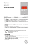
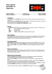
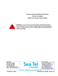
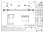
User manual
LMS Controller
8x Digital-in Module
for ALFANET
Description :
LMS CONTROLLER 8XDIG-IN MODULE
Type:
MANUAL
Number of pages:
File:
Do021330 LMS Controller
Digital-in Module v10 EN.wp8
LMS-Digin_V1.00
By:
Software:
VDH Products BV - Roden - Holland
Signed:
Doc. no. :
10
BJB
Version:
Date:
File:
021330
V1.0
15-08-2002
Doc'02
User Manual
LMS Controller 8xDIG-IN Module
Document no. : 021330
Version : V1.0
Client : General
Page : 2 of 10
Table of contents
1. Technical Specifications. . . . . . . . . . . . . . . . . . . . . . . . . . . . . . . . . . . . . . . . . . . . . . . . . . . . . . . . . . . 3
2. Functional Specifications. . . . . . . . . . . . . . . . . . . . . . . . . . . . . . . . . . . . . . . . . . . . . . . . . . . . . . . . . . .
2.1 Installation. . . . . . . . . . . . . . . . . . . . . . . . . . . . . . . . . . . . . . . . . . . . . . . . . . . . . . . . . . . . . .
2.2 Extension. . . . . . . . . . . . . . . . . . . . . . . . . . . . . . . . . . . . . . . . . . . . . . . . . . . . . . . . . . . . . . .
2.3 Operation . . . . . . . . . . . . . . . . . . . . . . . . . . . . . . . . . . . . . . . . . . . . . . . . . . . . . . . . . . . . . . .
4
4
4
4
3. Control. . . . . . . . . . . . . . . . . . . . . . . . . . . . . . . . . . . . . . . . . . . . . . . . . . . . . . . . . . . . . . . . . . . . . . . . . 5
3.1 Controlling. . . . . . . . . . . . . . . . . . . . . . . . . . . . . . . . . . . . . . . . . . . . . . . . . . . . . . . . . . . . . . 5
3.2 Readout. . . . . . . . . . . . . . . . . . . . . . . . . . . . . . . . . . . . . . . . . . . . . . . . . . . . . . . . . . . . . . . . 5
4. Viewing and changing Parameters. . . . . . . . . . . . . . . . . . . . . . . . . . . . . . . . . . . . . . . . . . . . . . . . . . . 6
4.1 Parameter list. . . . . . . . . . . . . . . . . . . . . . . . . . . . . . . . . . . . . . . . . . . . . . . . . . . . . . . . . . . . 7
5. Front view. . . . . . . . . . . . . . . . . . . . . . . . . . . . . . . . . . . . . . . . . . . . . . . . . . . . . . . . . . . . . . . . . . . . . . 8
6. Dimensions. . . . . . . . . . . . . . . . . . . . . . . . . . . . . . . . . . . . . . . . . . . . . . . . . . . . . . . . . . . . . . . . . . . . . 8
7. Connections. . . . . . . . . . . . . . . . . . . . . . . . . . . . . . . . . . . . . . . . . . . . . . . . . . . . . . . . . . . . . . . . . . . . 9
8. Address. . . . . . . . . . . . . . . . . . . . . . . . . . . . . . . . . . . . . . . . . . . . . . . . . . . . . . . . . . . . . . . . . . . . . . . 10
The information contained in this document is assumed to be accurate. However VDH Products BV
accepts no liability for eventual mistakes or errors and has the right to change this document without
notice.
User Manual
LMS Controller 8xDIG-IN Module
Document no. : 021330
Version : V1.0
Client : General
Page : 3 of 10
1. Technical Specifications.
Type
Power supply in
Current consumption
: LMS Controller 8x Digital-In Module
: 12Vdc (-5/+10%) from f.i. LMS-Supply-Module
: Max. 100mA
Control
Status indications
Inputs
: Thru PC
: LEDs on PC screen
: Max. 20 Digital contact inputs (NO or NC programmable) as follows:
8x Digital contact inputs (NO or NC programmable) on controller and
6x Digital contact inputs (NO/NC progr.) on LMS Dig-In Module-1 and
6x Digital contact inputs (NO/NC progr.) on LMS Dig-In Module-2
: Max. 16 Relays outputs on LMS Relays Modules
At max. 4 LMS Relays Modules can be connected thru the I2C-bus.
Each Module has 1 SPDT-output (C-NO-NC) and 3 SPST-outputs (C-NO)
available. Function of each relay is programmable on the PC as function
of the inputs.
: I2C-bus 0V, SCL,SDA (2-wire shielded min. 0,75mm 2, length max. 5
Meter ) Extension-bus for LMS Modules (Max. 2x LMS DIG-IN
MODULE and Max. 4x LMS RELAY MODULE).
RS485 0V, Line-A, Line-B (2-wire shielded min. 0,75mm 2, length max. 1
KM) For communication to the ALFANET PC-Interface, which is
connected with a PC.
Relays
Communication
Front
Housing dimensions
Panel cutout
Working temperature
Storage temperature
Working RH
: Material chrome polyester sticker
: 35 x 77 x 71,5mm (hdw)
: 28 x 70mm (hd) at panel mount
: -20/+50OC
: -20/+60OC
: 10/+90 % RH not condensing
- Provided with memory protection during power failure.
- Connection with screw-terminals.
User Manual
LMS Controller 8xDIG-IN Module
Document no. : 021330
Version : V1.0
Client : General
Page : 4 of 10
2. Functional Specifications.
2.1 Installation.
On the front of the LMS Controller 8xDigital-in Module and at the connection diagram is shown
how the inputs, power-supply, I2C-bus and RS485-network connection must be connected to the
controller.
After connecting the Controller to the power supply, a self-test function starts.
The Controller is thru the ALFANET PC-INTERFACE on the PC programmable.
A maximum of eight LMS Controller 8xDigital-in Modules can be placed on the RS485-network.
These modules must have unique network numbers. Through the jumpers under the screw cover
this can be adjusted from address 101 to 108.
2.2 Extension.
The Controller can be further extended with a maximum of two I2C LMS Digital-In Modules and
a maximum of four I2C LMS Relay Modules.
Each similar type of LMS-Module must then have a unique I2C address (see the jumper settings in
the connection data).
This brings the total to a maximum of 20 digital inputs and 16 relay outputs.
2.3 Operation.
On the PC it is possible to see whether a input is active or not (see LEDs in window).
If there is a fatal alarm a warning box will appear registering the alarm.
The action of every input is registered in the log.
The following functional settings can be made in the parameter list;
Param.
Description
xx00
- Every input can be made active (yes) or turned off (no).
xx01
- All inputs can be made active if it is closed (normally open (yes)) or
Made active as the input disconnects (normally open (no)= normally closed).
xx02
- Additional every input can be set as an fatal alarm (yes or no), so that in case of
fatal alarm the relay of the PC-Interface will also be activated.
xx03
- Furthermore every input can be coupled to one of the sixteen relay outputs.
Whereby it is also possible to select several inputs to drive one and the same relay.
xx04/xx07 - The controller has a on- and a off-switch delay per input in seconds or minutes,
xx08
- Every input can have a maximal time relay active setting (0 = continue).
xx09
- Every input can be set to compulsory confirmation (or acknowledge mandatory).
This means that when the input becomes active again, it still remembers this alarm
after recovering until the reset button (one of the digital inputs programmed as
reset) is pressed.
xx10
- Every input can also be set as resettable, making it possible to deactivate an
(alarm) input with reset before it has been recovered.
xx11
- Every input can also be defined as a reset_input, so that alarms that are
remembered can be reset. Reset can also be given via the PC.
If more inputs are adjusted for this function then they work as one reset, normally
one input as reset will be enough.
3000/3015 - Every relay output can be defined to be a control or watch relay.
At control the relay comes active as the function becomes active, at watch the relay
is normally active and it deactivates as the function becomes active.
Whereby xx is the number of the input ( 1 ... 20)
User Manual
LMS Controller 8xDIG-IN Module
Document no. : 021330
Version : V1.0
Client : General
Page : 5 of 10
3. Control.
3.1 Controlling.
The Controller can only be controlled with the PC. To do so, see also the manual of the ALFANET
PC-INTERFACE.
3.2 Readout.
The figure below shows how the Digital-in Module is shown on the PC.
The LEDs give the status of inputs (LED active as input is active).
The three frames show respectively the Alfanet LMS CONTROLLER 8xDIG-IN MODULE and the
optional I2C modules.
Alfanet Digital in
module
1
2
3
4
5
6
7
8
I2C LMS
Digital in (1)
I2C LMS
Digital in (2)
9 11 13
10 12 14
15 17 19
16 18 20
A name can be coupled to this LED’s status in the LOG-menu of the PC-Software. This is then
shown when the cursor is above the LED.
For the naming of the module (Alfanet digital-in module (101)) see the PC-software manual.
The status of the relays of the optional I2C LMS_RELAY_MODULES are not shown. They are
coupled to a particular input, via the parameters.
User Manual
LMS Controller 8xDIG-IN Module
Document no. : 021330
Version : V1.0
Client : General
Page : 6 of 10
4. Viewing and changing Parameters.
Thru the context menu (= right-mouse button) the parameters can be readout or changed.
User Manual
LMS Controller 8xDIG-IN Module
Document no. : 021330
Version : V1.0
Client : General
Page : 7 of 10
4.1 Parameter list.
Remark: xx = 01 .. 20, the input contact number;
Param
eter
Description Parameter
Range
Default
Value
xx00
Input xx active
0
xx01
Input xx normally open
xx02
Input xx fatal alarm
xx03
Input xx relay number active at contact
xx04
Input xx switching on delay
0=no
1=yes
0=no
1=yes
0=no
1=yes
0..16
0 = no relay
0 .. 240
xx05
Input xx switching on delay in sec/min
0
xx06
Input xx switching off delay
0 = seconds
1 = minutes
0 .. 240
xx07
Input xx switching off delay in sec/min
0
xx08
Input xx maximum time relay active
xx09
xx10
Input xx Acknowledge mandatory
(must be conformed)
Input xx is resettable
xx11
Input xx is reset-input
0 = seconds
1 = minutes
0 .. 240 minutes
0 = continuous
0=no
1=yes
0=no
1=yes
0=no
1=yes
3000
3001
3002
3003
Relay
Relay
Relay
Relay
1 = watch relay
2 = watch relay
3 = watch relay
4 = watch relay
0=no, 1=Yes
0=no, 1=Yes
0=no, 1=Yes
0=no, 1=Yes
0
0
0
0
3004
3005
3006
3007
Relay
Relay
Relay
Relay
5 = watch relay
6 = watch relay
7 = watch relay
8 = watch relay
0=no, 1=Yes
0=no, 1=Yes
0=no, 1=Yes
0=no, 1=Yes
0
0
0
0
3008
3009
3010
3011
Relay 9 = watch relay
Relay 10 = watch relay
Relay 11 = watch relay
Relay 12 = watch relay
0=no, 1=Yes
0=no, 1=Yes
0=no, 1=Yes
0=no, 1=Yes
0
0
0
0
3012
3013
3014
3015
Relay 13 = watch relay
Relay 14 = watch relay
Relay 15 = watch relay
Relay 16 = watch relay
0=no, 1=Yes
0=no, 1=Yes
0=no, 1=Yes
0=no, 1=Yes
0
0
0
0
9995
Software version
-
-
0
0
0
0
0
0
0
0
0
User Manual
LMS Controller 8xDIG-IN Module
Document no. : 021330
Version : V1.0
Client : General
Page : 8 of 10
5. Front view.
Drawing 011819
6. Dimensions.
User Manual
LMS Controller 8xDIG-IN Module
Document no. : 021330
Version : V1.0
Client : General
Page : 9 of 10
7. Connections.
Drawing 011818
Drawing 011823 Connections LMS Controller 8xDIG-IN Module with maximum extension
User Manual
LMS Controller 8xDIG-IN Module
Document no. : 021330
Version : V1.0
Client : General
Page : 10 of 10
Drawing 011846 Maximum configuration on one RS485-Network
8. Address.
VDH Products BV
Produktieweg 1
9301 ZS Roden
The Netherlands
@
Telephone
+31 (0)50 - 30 28 900
Fax
+31 (0)50 - 30 28 980
Email:
[email protected]
Internet:
www.vdhproducts.nl