1
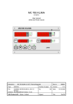
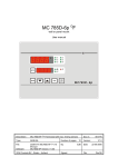
SPRAYTRONIC® with QDS USER MANUAL Description : Type: SPRAYTRONIC® MANUAL Number of pages: File: Do040089 Spraytronic QDS v14 EN.wpd Software: SPRAYTRONIC Version: V1.20 By: VDH Products BV - Roden - Holland Signed: 12 BJB Doc.nr.: 040089 Version: V1.4 Date: File: 12-05-2011 Doc'04 User manual ® SPRAYTRONIC Document nr. : 040089 Version: Client : General Page : V1.4 2 of 12 Table of Contents 1. 1.1 1.2 1.3 Technical specifications . . . . . . . . . . . . . . . . . . . . . . . . . . . . . . . . . . . . . . . . . . . . . . . . . . . . . . . . General . . . . . . . . . . . . . . . . . . . . . . . . . . . . . . . . . . . . . . . . . . . . . . . . . . . . . . . . . . . . . . . . . . . . Front . . . . . . . . . . . . . . . . . . . . . . . . . . . . . . . . . . . . . . . . . . . . . . . . . . . . . . . . . . . . . . . . . . . . . . . In- and Outputs . . . . . . . . . . . . . . . . . . . . . . . . . . . . . . . . . . . . . . . . . . . . . . . . . . . . . . . . . . . . . . 3 3 3 4 2. Functional specifications . . . . . . . . . . . . . . . . . . . . . . . . . . . . . . . . . . . . . . . . . . . . . . . . . . . . . . . 5 3. 3.1 3.2 3.3 3.4 3.5 3.6 3.7 3.8 3.9 3.10 3.11 3.12 3.13 3.14 Control . . . . . . . . . . . . . . . . . . . . . . . . . . . . . . . . . . . . . . . . . . . . . . . . . . . . . . . . . . . . . . . . . . . . . Switching the Spraytronic on/off. . . . . . . . . . . . . . . . . . . . . . . . . . . . . . . . . . . . . . . . . . . . . . . . . . Read-out of the channel temperature. . . . . . . . . . . . . . . . . . . . . . . . . . . . . . . . . . . . . . . . . . . . . . Looking at the spray and dry setpoint. . . . . . . . . . . . . . . . . . . . . . . . . . . . . . . . . . . . . . . . . . . . . . Setting of the spray and dry setpoint. . . . . . . . . . . . . . . . . . . . . . . . . . . . . . . . . . . . . . . . . . . . . . Read-out of the P(I) output. . . . . . . . . . . . . . . . . . . . . . . . . . . . . . . . . . . . . . . . . . . . . . . . . . . . . . Read-out and setting of Setpoint Delta. . . . . . . . . . . . . . . . . . . . . . . . . . . . . . . . . . . . . . . . . . . . . Setting of the dry time. . . . . . . . . . . . . . . . . . . . . . . . . . . . . . . . . . . . . . . . . . . . . . . . . . . . . . . . . . Starting of the drying. . . . . . . . . . . . . . . . . . . . . . . . . . . . . . . . . . . . . . . . . . . . . . . . . . . . . . . . . . . Read-out of dry hours. . . . . . . . . . . . . . . . . . . . . . . . . . . . . . . . . . . . . . . . . . . . . . . . . . . . . . . . . . Read-out of operation hours. . . . . . . . . . . . . . . . . . . . . . . . . . . . . . . . . . . . . . . . . . . . . . . . . . . . . Switch on energy mode. . . . . . . . . . . . . . . . . . . . . . . . . . . . . . . . . . . . . . . . . . . . . . . . . . . . . . . . QDS = Quick Dry System. . . . . . . . . . . . . . . . . . . . . . . . . . . . . . . . . . . . . . . . . . . . . . . . . . . . . . . Hall heating. . . . . . . . . . . . . . . . . . . . . . . . . . . . . . . . . . . . . . . . . . . . . . . . . . . . . . . . . . . . . . . . . . Master / Slave operation. . . . . . . . . . . . . . . . . . . . . . . . . . . . . . . . . . . . . . . . . . . . . . . . . . . . . . . . 4. 4.1 Programming internal settings . . . . . . . . . . . . . . . . . . . . . . . . . . . . . . . . . . . . . . . . . . . . . . . . . . . 8 Parameter table. . . . . . . . . . . . . . . . . . . . . . . . . . . . . . . . . . . . . . . . . . . . . . . . . . . . . . . . . . . . . . . 8 5. Operation temperature control . . . . . . . . . . . . . . . . . . . . . . . . . . . . . . . . . . . . . . . . . . . . . . . . . . . 9 6. Sensor calibration . . . . . . . . . . . . . . . . . . . . . . . . . . . . . . . . . . . . . . . . . . . . . . . . . . . . . . . . . . . . 9 7. Relay test . . . . . . . . . . . . . . . . . . . . . . . . . . . . . . . . . . . . . . . . . . . . . . . . . . . . . . . . . . . . . . . . . . . 9 8. Alarms . . . . . . . . . . . . . . . . . . . . . . . . . . . . . . . . . . . . . . . . . . . . . . . . . . . . . . . . . . . . . . . . . . . . . 9 9. Front view . . . . . . . . . . . . . . . . . . . . . . . . . . . . . . . . . . . . . . . . . . . . . . . . . . . . . . . . . . . . . . . . . . 10 10. Connection diagram . . . . . . . . . . . . . . . . . . . . . . . . . . . . . . . . . . . . . . . . . . . . . . . . . . . . . . . . . . 11 11. Dimensions . . . . . . . . . . . . . . . . . . . . . . . . . . . . . . . . . . . . . . . . . . . . . . . . . . . . . . . . . . . . . . . . 12 6 6 6 6 6 6 6 6 6 6 6 7 7 7 7 The information contained in this document is assumed to be accurate. However VDH Products BV accepts no liability for eventual mistakes or errors and has the right to change this document without notice. User manual ® SPRAYTRONIC 1. Document nr. : 040089 Version: Client : General Page : V1.4 3 of 12 Technical specifications 1.1 General Type name Housing Material Dimensions Panel cut Front Range Power supply Power consumption Operating temperature Store temperature Operating RH Accuracy 1.2 Front Display Led's Keys : SPRAYTRONIC® : Panel mounting : Steel painted silver grey : 217 x 155 x 85mm (whd) : min. 208 x 146mm (wh) : Polycarbonate (IP-44) : 0/+150C per 0,5C : 230 Vac; 50/60 Hz (-10/+5%). : 9 VA : -20/+50C : -20/+60C : 10/+90 % RH not condensing : ± 0,5 % of the range : 4-number digital display for cabine temperature 4-number digital display for temperature setpoint 4-number digital display for spray hours counter 4-number digital display for dry timer : >, High = Burner in high position (modulating) <, On = Burner is on (low modulating) Intake = Intake fan on Exhaust = Exhaust fan on Spraying = Spray setpoint in display Drying = Dry setpoint in display IRS Spraying = SPRAYTRONIC® in spray mode IRS Timer = SPRAYTRONIC® in hold mode IRS Recirculation = SPRAYTRONIC® in recirculation Drying = SPRAYTRONIC® in dry mode Down Cooling = SPRAYTRONIC® in cooling down mode : SETP. = Setpoint key START DRYING = Start of dry timer PI = Read out PI-output with LED = Down key = Up key CHAN. TEMP. = Read out channel temperature with LED SETP. DELTA = Setpoint delta temperature with LED DRYING TIME = Set dry time with LED DRYING HOURS = Read-out dry hours with LED OPERAT. HOURS = Read-out running hours with LED ENERGY SWITCH = Switch off IRS (hand spraying) QDS = Quick Dry System on/off key with LED indication User manual ® SPRAYTRONIC 1.3 In- and Outputs Sensors Digital inputs Analog output Network Relays Document nr. : 040089 Version: Client : General Page : V1.4 4 of 12 : Cabine temperature sensor (Pt100, 3-wire to DIN/IEC 751) Channel temperature sensor (Pt100, 3-wire to DIN/IEC 751) IRS sensor (spraying detector) (2-wire +/-) : IN1: Operation on input (potential free input contact) IN2: Down cool thermostat on input (potential free input contact) IN3: Door contact master/slave, Start QDS, (potential free input contact) or Hall-heating thermostat input : 0/+10Vdc Analog output for proportional burner valve, (Rbmin 10Kohm.) release burner or hall-heating : Optional RS485 network connections (2-wire shielded) For Master/Slave connection. NOTE !! Network cable on both ends connected with a 250 Ohm resistor between connection A and B. : RY1 Burner high/low (Hi-mod) (C/NO/NC, 250Vac/10A not inductive) The following relays have a central common; RY2 Burner on/off (Lo-mod) (NO, 250Vac/10A not inductive) RY3 Intake fan on/off (NO, 250Vac/10A not inductive) RY4 Exhaust fan on/off (NO, 250Vac/10A not inductive) RY5 Release Burner or QDS (NO/NC, 250Vac/10A not inductive) User manual ® SPRAYTRONIC 2. Document nr. : 040089 Version: Client : General Page : V1.4 5 of 12 Functional specifications The SPRAYTRONIC® has the following functions: A control thermostat for the heating. A setpoint for spraying and a setpoint for drying, can be set. The controller has a high/low mode for the burner, and has a P(I) 0-10Vdc output for proportional burner control. The SPRAYTRONIC® can also be used as plant heating. Further is a QDS= Quick Dry System for water containing coatings at hand. The burner is only switched on if the supply fan is on. The supply fan is always on. Temperature control is done via the cabine sensor. Is also the channel sensor connected, then the temperature during spraying is controlled by the channel sensor. This provides that the cabine is quicker on the set temperature. There are 4 types of burners available for temperature control; On/off burner control with RY2-relay as burner on/off function. High/low burner control with RY2-relay as burner on/off and RY1-relay as high/low function. Left/Right modulating burner control with RY2-relay as low-modulation function and RY1-relay as high-modulation function, whereby the P(I) output as burner-release function operates. Proportional (Integrating) burner valve control with the 0-10Vdc analog output and RY2-relay as burner on/off function. Also the controller can control the hall-heating (only with On/off burner control or High/low burner control) as the SPRAYTRONIC® is off. In this case is the channel sensor is a maximum thermostat for the hall heating (via parameter P70 and P71) With the external operating switch the SPRAYTRONIC® is put in recirculation mode. The cabine is kept at spray temperature and the supply fan is on. If the optional IRS sensor is connected and the energy switch is off, this sensor detects, if there is really being sprayed. If spraying is in progress, this is detected by the IRS sensor and switches the SPRAYTRONIC® into spray mode. Now the extract fan is switched on. After spraying the IRS switches into hold time mode. The spraying can be continued directly. If the IRS hold time is past, the SPRAYTRONIC® switches back to recirculation. If the energy switch is on, the SPRAYTRONIC® is always in spray mode. With the energy switch it is always possible to choose between spraying and recirculation (if the operation switch is on), also if no IRS sensor is connected. After the dry time is set, the drying can be started. The SPRAYTRONIC® switches to drying and only the supply fan is on. If after the drying the operation switch is still on, the SPRAYTRONIC® brings the temperature down to the spray temperature + setpoint delta. This function is always active in the recirculation mode. Is the operation switch off, the supply and extract fans remain on, until they are switched off by the external down-cool thermostat. User manual ® SPRAYTRONIC 3. Document nr. : 040089 Version: Client : General Page : V1.4 6 of 12 Control During normal operation the displays of the SPRAYTRONIC® indicate the cabin temperature, spray setpoint, spray hours and the dry time. 3.1 Switching the Spraytronic on/off. To activate the SPRAYTRONIC®, the external operation switch (digital input 1) needs to be switched on. The setpoint display shows the spray setpoint, the spray hours counter the number of spray hours and the dry timer the last set dry time. The SPRAYTRONIC® switches to recirculation mode and the supply fan goes on. This is indicated by the LED's in the display. 3.2 Read-out of the channel temperature. Press the CHAN. TEMP. key. If this sensor is present, the temperature display shows the channel temperature. After releasing this key, the cabin temperature is shown again. 3.3 Looking at the spray and dry setpoint. The LED next to the setpoint display indicates if the spray or dry setpoint is shown. By pushing the UP or DOWN key the other setpoint is shown. The LED of that setpoint starts flashing. After releasing the UP or DOWN key appears the other setpoint again in the display. 3.4 Setting of the spray and dry setpoint. Make sure that the setpoint that needs to be changed is shown in the display and push the SETP. key. The setpoint starts flashing and can be adjusted with the UP and DOWN keys. Press the SETP. key once again to accept the new setpoint. 3.5 Read-out of the P(I) output. Press the PI key to show the value of the analog output (0-10Vdc) in percentage (0-100%) in the setpoint display. After releasing the PI key appears the active setpoint again in the display. 3.6 Read-out and setting of Setpoint Delta. Press the SETP. DELTA key. The delta setpoint appears flashing in the setpoint display. With the UP and DOWN keys the delta setpoint can be adjusted. By pressing the SETP. DELTA key again, the new value is accepted. 3.7 Setting of the dry time. Press the DRYING TIME key. The time in the dry hours display is blinking. With the UP and DOWN keys a new dry time can be set. By pressing the DRY TIME key again, the new time is accepted. During drying the remaining dry time is indicated. This remaining dry time can also be adjusted by pressing the DRYING TIME key. The remaining dry time in the dry hours display is blinking. With the UP and DOWN keys the remaining dry time can be adjusted. By pressing the DRYING TIME key again, the new remaining dry time is accepted. 3.8 Starting of the drying. After the required dry time is set, can by pushing the START DRYING key the drying be started. The SPRAYTRONIC® switches to the dry mode, the dry setpoint appears in the setpoint display and the LED drying lights. If the dry time is passed, the supply and extraction fan go on. If the operation switch is on, the cabine is cooled down to spray setpoint + setpoint delta. Is the operation switch off, the fans are stopped by the external thermostat. 3.9 Read-out of dry hours. Press the DRYING HOURS key. In the spray hours display, the dry hours are shown. 3.10 Read-out of operation hours. Press the OPERAT. HOURS key. In the spray hours display the running hours are shown. User manual ® SPRAYTRONIC Document nr. : 040089 Version: Client : General Page : V1.4 7 of 12 3.11 Switch on energy mode. By pressing the ENERGY SWITCH key the SPRAYTRONIC® switches into the spray mode. The LED above the key is on. By pressing the ENERGY SWITCH key again, the controller is switched into recirculation mode. This key is used for continuously spraying or if no IRS sensor is present for manual spraying. 3.12 QDS = Quick Dry System. The Quick-Dry-System is a drying process specially added for water containing coatings. When the QDS is switched off it has no effect on the rest of the control-system. To put the QDS system on press QDS key or via the external start QDS (Digital-in.4, if parameter P09=0), to indicate the QDS mode is on the LED above the QDS key will light. The QDS time (P36) starts, during this time the controller brings the temperature of the cabine QDS-delta (P35) higher than the recirculation temperature(f.i. to 40OC). Now the water can evaporate from the coating. After the QDS time the controller switches back to the normal recirculation temperature. While QDS is active the setpoint delta is deactivated. As parameter P60 is set to 1, relay RY5 is active as the QDS function is active. 3.13 Hall heating. The SPRAYTRONIC® can also be used as hall heating controller if internal parameter P09 is set to 3 = Hall heating. And works only for burner types P50 = 0 (On/Off) or P50 = 1 (High/Low). The hall heating can only becomes active as the SPRAYTRONIC® is switched off (Digital input.1 is disconnected), the switch on delay of 10 seconds is passed and the cool down thermostat is not active. Than the SPRAYTRONIC® operates as hall heating by looking at the hall-heating thermostat input (Digital input.4). If the hall thermostat contact is closed, the controller active the analog output to 10Vdc, sets relay RY2 (burner on) on, sets relay RY1 (low at H/L-type) off and relay RY3 (supply fan) on. Is the hall thermostat contact open, than the controller sets the analog output to 0Vdc, relay RY2 (burner on) off, relay RY3 (supply fan) off. If the cool down thermostat becomes active after this the hall heating is disabled, and this cool down function is activated first and after this down cooling of the cabine the hall heating is enabled again. Switches the SPRAYTRONIC® on again (Digital input.1 is connected), than the hall heating is blocked. 3.14 Master / Slave operation. The SPRAYTRONIC® can also used in master/slave configuration via parameter P09. Whereby, the RS485 network connection needs to be made between the master and the slave. At closing the door contact (door is open) the SPRAYTRONIC® which is programmed as master, will work as Master, where the Slave will follow the functional operation of the master. The Slave can't be controlled. When opening the door contact (door closes) each controller will automatically work as stand-alone unit. The master/slave functions don't work if parameter P09 is set on 3 (Hall heating). User manual ® SPRAYTRONIC 4. Document nr. : 040089 Version: Client : General Page : V1.4 8 of 12 Programming internal settings By pushing the DRYING HOURS and OPERAT. HOURS keys for more than 5 seconds simultaneously, the Internal Parameters are shown. In the temperature display appears a P with a number behind it. In the setpoint display appears the value of the parameter. With the UP or DOWN key the required parameter can be selected. If the required parameter is reached, the value can be adjusted by pushing the SETP and the UP and DOWN key simultaneously. If during 30 seconds no key is touched or simultaneously pressed on the DRY HOURS and RUNNING HOURS keys, the SPRAYTRONIC® returns to the normal operation mode. 4.1 Nr P 01 P 02 P 03 P 04 P 05 P 06 P 07 P 08 P 09 Parameter table. Describtion Differential spraying Differentie drying Offset spraying Offset drying Burner high at larger difference Setpoint - Cabine temperature Proportional band Integration time (999 = only P) Differential Delta T Master-Slave configuration 0 = Stand alone (0=Start QDS on Dig.in-4) 1 = Master 2 = Slave 3 = Hall heating P 10 P 11 P 12 P 13 Channel sensor present Control on channel sensor Offset cabine sensor Offset channel sensor P 20 P 21 P 22 Minimum setpoint setting Maximum setpoint setting Maximum temperature ascending during drying P 30 P 31 P 32 IRS sensor present IRS hold time Start delay extraction fan compared to the supply fan P 35 P 36 QDS delta temperature raising QDS running time P 40 P 41 P 42 Reset spray hours Reset dry hours Reset running hours P 50 Burner mode 0 = On/off type 1 = High/low type 2 = Left/right modulating type 3 = P(I)-valve control type Burner transit time D-action Burner release offset (at P50=2 and P09 is not 3) Burner release switch-off delay (at P50=2 and P09 is not 3) P 51 P 52 P 53 P 54 Range Unit Default 1..15 1..15 -15..+15 -15..+15 0..15 °C °C °C °C °C 1 1 0 0 2 1..+15 0..99 1.0..15.0 0..3 °C minutes °C - 5 2 1 0 0=no, 1=yes 0=no, 1=yes -10..+10 -10..+10 °C °C 0 0 0 0 0..150 0..150 1..200 °C °C °C/min. 0 100 10 0=no, 1=yes 0..99 0..99 minutes seconds 1 1 15 0..50 0..99 °C minutes 15 10 0=no, 1=yes 0=no, 1=yes 0=no, 1=yes - 0 0 0 0..3 - 0 10..200 0...1000 1..10 0..240 seconds % °C seconds 50 50 2 30 User manual ® SPRAYTRONIC Nr P 60 P61 P 70 P 71 P 90 P 91 P 92 5. Document nr. : 040089 Version: Client : General Page : Describtion 9 of 12 Range Unit Default 0..2 - 0 0..1 - 0 20..80 °C 50 1..20 °C 10 - year/wk - Function relay RY5 0 = Burner release 1 = QDS active 2 = Dry mode actief Function exhaust fan 0 = Only on at spraying 1 = Only off at drying Maximum channel temperature at hall heating Maximum channel temperature differential at hall heating V1.4 Software version number Serial number Production date Operation temperature control The heating switches on if the temperature is below setpoint + offset + differential and switches off it the temperature has raised above setpoint + offset. At burner mode type 2 (Left/Right modulating) the analog output (connected to f.i. KBR610-EI) operates as burner release as follows; 0V: If during the burner release delay time (P54) the temperature is higher or equal to setpoint + burner_release_offset (P53). 10V: As the temperature is lower or equal to setpoint + burner_release_offset (P53) - 1°C. 6. Sensor calibration With parameter P12 and P13 the cabin and channel sensor can be calibrated. Indicates a sensor e.g. 2C too much, the according offset parameter needs to be set at 2C lower. 7. Relay test With the relay test the relay outputs can be tested independently. To get into the relay test mode the SPRAYTRONIC® needs to be disconnected from the main power. Push the PI key while the power supply is connected again. The controller is now in the relay test mode. The temperature display indicates ‘0' as sign that none of the relays is on. With the UP and DOWN keys the relays can be selected; '1' = relay 1, '2' = relay 2 etc. To stop the relay test mode, disconnect the power supply again from the instrument. 8. Alarms In the display the following alarm messages can appear flashing in the display: E1 = Cabine sensor broken. The temperature control stops. E2 = Channel sensor broken. The temperature control switches over to cabine sensor. E3 = general failure. Contact your supplier/installer. The error message remains in the display until the failure is solved. User manual ® SPRAYTRONIC 9. Document nr. : 040089 Version: Client : General Page : Front view Frontview SPRAYTRONIC® drawing 9040098w0 V1.4 10 of 12 User manual ® SPRAYTRONIC Document nr. : 040089 Version: Client : General Page : V1.4 11 of 12 10. Connection diagram Connections SPRAYTRONIC® drawing 040097w1 NOTE ! Use network cable in M/S (Master/Slave) operation (2-wire shielded). To both ends of the cable a terminator resistor of 250 Ohm needs to be connected between line-A and line-B. User manual ® SPRAYTRONIC 11. Document nr. : 040089 Version: Client : General Page : Dimensions Panel mounting SPRAYTRONIC® drawing 961271 -.-.-.-.-.-.-.-.-.@ V1.4 12 of 12