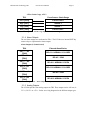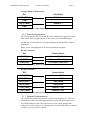
1
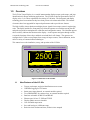
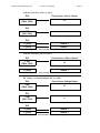
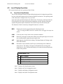
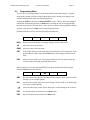
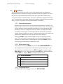
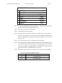
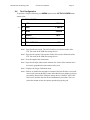
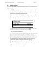
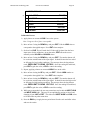
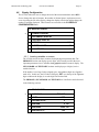
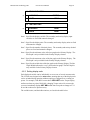
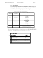
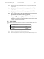
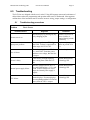
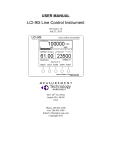
USER MANUAL LCI-80x Torque Display Revision 1.20 December 30, 2013 4211 24th Ave West Seattle WA 98199 USA Phone: 206.634.1308 Fax: 206.634.1309 Email: [email protected] Copyright 2013 Measurement Technology NW LCI-80x User Manual Page 2 Table of Contents 1.0 Overview ......................................................................................................................... 5 1.1 2.0 New Features of the LCI-80x................................................................................................ 5 Mechanical Installation ................................................................................................. 6 2.1 Environmental Considerations............................................................................................. 6 2.2 Dimensions and Cutout ......................................................................................................... 6 2.3 Display Mounting .................................................................................................................. 6 2.4 Ventilation Requirements ..................................................................................................... 6 2.5 Cleaning Instructions ............................................................................................................ 6 3.0 Wiring Diagrams ............................................................................................................ 7 3.1 Wiring Hookup – Local Display ........................................................................................... 7 3.1.1 3.1.2 3.1.3 3.1.4 3.1.5 3.1.6 3.1.7 4.0 Display power and fuse .................................................................................................................. 7 Power for Field Sensors ................................................................................................................. 8 Torque Sensor Inputs ..................................................................................................................... 8 Alarm Outputs ..............................................................................................................................11 Analog Outputs .............................................................................................................................11 Serial Communications .................................................................................................................12 Ethernet Communications .............................................................................................................12 Local Display Operation .............................................................................................. 14 4.1 Front Panel Identification................................................................................................... 14 4.2 Programming Menu ............................................................................................................ 15 4.3 Alarms .................................................................................................................................. 16 4.3.1 4.3.2 4.3.3 Acknowledging alarms .................................................................................................................16 Setting alarm limits .......................................................................................................................16 Configuring Alarms ......................................................................................................................16 4.4 Tool Configuration .............................................................................................................. 18 4.5 Torque Calibration.............................................................................................................. 19 4.5.1 4.5.2 4.6 Display Configuration ......................................................................................................... 21 4.6.1 4.6.2 4.6.3 4.6.4 4.6.5 4.6.6 5.0 Scale and offset .............................................................................................................................19 Two-point live calibration ............................................................................................................19 Locating variables on screen .........................................................................................................21 Setting display units ......................................................................................................................22 Setting decimal places ..................................................................................................................23 Setting Bar Graph Range ..............................................................................................................23 Screen Saver .................................................................................................................................23 Display Refresh Rate ....................................................................................................................23 Hardware Configuration ............................................................................................. 24 5.1 ADMIN ................................................................................................................................. 24 5.1.1 5.1.2 5.1.3 5.1.4 NAME ..........................................................................................................................................24 LANGAUGE ................................................................................................................................24 SECURITY ...................................................................................................................................24 FACTORY SETUP ......................................................................................................................24 Measurement Technology NW 5.1.1 5.1.2 5.1.3 5.1.4 5.2 LCI-80x User Manual Page 3 Save Setup ....................................................................................................................................25 Load Setup ....................................................................................................................................25 Current Setup ................................................................................................................................25 DATE and TIME ..........................................................................................................................26 SENSOR CONFIG .............................................................................................................. 26 5.2.1 5.2.2 5.2.3 5.2.4 5.2.5 5.2.6 SAMPLING ..................................................................................................................................26 TORQUE SETUP .........................................................................................................................26 AIN CONFIG ...............................................................................................................................27 AOUT CONFIG ...........................................................................................................................28 Calibrating the analog output signal .............................................................................................29 DIG I/O CONFIG .........................................................................................................................29 5.3 Communication ................................................................................................................... 29 5.4 USB STORAGE ................................................................................................................... 30 6.0 Troubleshooting ........................................................................................................... 31 6.1 Troubleshooting procedures ............................................................................................... 31 6.2 Technical support ................................................................................................................ 34 7.0 Appendix A – Dimensional Drawing .......................................................................... 35 8.0 Appendix B – DIP Switch Settings .............................................................................. 36 9.0 Appendix F – LCI-80x Specifications ......................................................................... 37 10.0 Appendix G – LCI-80x Wire List ............................................................................. 39 11.0 LCI-80x Terminal Board Interface.......................................................................... 40 12.0 Appendix H – LCI-80x Gimbal Bracket Mounting Footprint ................................ 41 Measurement Technology NW LCI-80x User Manual Page 4 Figures Figure 1.1 Illustration of the LCI-80x....................................................................................... 5 Figure 11.1 LCI-80x Terminal Board Interface ...................................................................... 40 Figure 12.1 LCI-80x Gimbal Bracket Dimensions ................................................................. 41 Tables Table 3.1 Identification of hardware interconnect and DIP Switch .......................................... 7 Table 3.2 Fuse Rating and Replacement Part Numbers ........................................................... 8 Table 3.3 Regulated DC Power Supplies for Field Sensors ..................................................... 8 Table 4.1 Contact Relay Module Locations ........................................................................... 17 Table 4.2 Available Torque Units ........................................................................................... 23 Table 5.1 Analog Input Channel Definitions .......................................................................... 27 Table 5.2 Analog Output Locations and Menu Names........................................................... 28 Table 0.1 RS-485 Termination Settings.................................................................................. 36 Table 0.2 Analog Input Termination Settings......................................................................... 36 Table 10.1 LCI-80x Wire List ................................................................................................ 39 Measurement Technology NW 1.0 LCI-80x User Manual Page 5 Overview The LCI-80x Torque Display is a versatile instrument that displays torque, peak torque, and joint identification for torque monitoring applications. The LCI-80x is the next generation of the LCI display series. It is a direct replacement for existing LCI-80 units. The front panel and display technology have been retained as they have been proven to be robust and reliable. The internal electronics have been upgraded for improved performance and to provide new features. The high visibility electro-luminescent display shows signals from a torque sensor in engineering units. The display and the five front panel keys allow the operator to record the current joint ID and peak torque and to manipulate the calibration and configuration menus. The label that appears above each key indicates the function on the display. As the operator navigates through various screens the functions of these keys and their associated labels will change. The operator can configure the LCI-80x to accept inputs from a range of torque sensors, sensor calibration, and to utilize a variety of communication technologies. This manual covers the installation, set-up, and operation of the LCI-80x. LCI-80 LINE CONTROL INSTRUMENT TORQUE – LBFT REC OK 2500 0 PEAK 2600 JOINT 654321 5000 MEN ALM CLR JNT REC ^ ^ ^ ^ ^ MEASUREMENT TECHNOLOGY NW www.mtnw-usa.com Figure 1.1 Illustration of the LCI-80x 1.1 New Features of the LCI-80x Torque, peak torque, and joint identification on one screen. USB Data Logging in CSV format Strain gauge input channels, no external module required Two onboard SPDT dry contact relays, no external modules required Baud rate selectable for RS-232 and RS-485 Ethernet port, 10 base T, UDP and TCP/IP Display update rate user selectable User selectable torque units Save and load up to 4 different setups Real-time clock for date and time, all data is time stamped Measurement Technology NW 2.0 LCI-80x User Manual Page 6 Mechanical Installation The LCI-80x is designed for mounting on the front-panel of an electrical enclosure with a suitable environmental rating. The sealed front face of the LCI-80x is made of a laminated stainless steel assembly and the slotted rear cage is designed to promote heat transfer, facilitate field wire terminations, and provide a purchase point for the panel clamps. The front face is 3.9” high x 5.6” wide and the total depth is 2.38” (measured from the rear of the stainless steel front panel to the rear extremity of the LCI-80x’s enclosure). 2.1 Environmental Considerations The front face of the LCI-80x is designed for NEMA 4X applications. It consists of a 316 stainless steel top layer, a sealed polycarbonate window, and five membrane-sealed stainless steel push buttons. A polyurethane gasket, held in-place by a high temperature adhesive is applied to the backside of the front face. When mounting the LCI-80x in exposed locations, a front-panel cover is recommended to protect the unit when it is not in use. The standard temperature range of the LCI-80x is –40°C to +70°C. 2.2 Dimensions and Cutout The LCI-80x will fit in a 5.27” x 3.55” cutout (tolerance –0.01, +0.100); with a minimum of 2.38” depth clearance (see Appendix A for dimensional drawing). The enclosure’s front panel can be up to 5/8” thick. 2.3 Display Mounting The instrument is held in place with removable panel clamps that index into the slotted holes on all sides of the display. Two clamps are included with each display. After sliding the display into the cutout, clip the two panel clamps on to the sides of the display, using the slotted grooves on the display’s enclosure, with the flanged end of the clamp facing away from the panel. Once the panel clamps are installed, tighten the jackscrews against the panel to compress the LCI-80x gasket to seal against the panel. Lock the jackscrews with the provided hex nuts to prevent them from vibrating loose over time. Care should be taken to not over tighten the jackscrews. 2.4 Ventilation Requirements The instrument should be mounted with a minimum of 0.75” spacing between the rear enclosure (all edges) of the display and adjacent equipment to allow for adequate ventilation and heat transfer. 2.5 Cleaning Instructions To clean the front panel of the display, use a clean lint free cloth and a high quality and pure isopropanol. Do not apply the mild solvent directly to the polycarbonate window, instead wet the cloth or wipe first and then gently wipe the window and the stainless steel bezel. Measurement Technology NW 3.0 LCI-80x User Manual Page 7 Wiring Diagrams The LCI-80x can be configured for a wide range of signal input and output functions. Configuration consists of wiring and menu settings, and in the case of analog inputs and RS-485 serial communications, DIP switch settings as well. The wiring diagrams are given in this section. The table below gives of a summary of the LCI-80x functions referenced to their associated menu and DIP switch numbers, required hardware options, and section of this manual covering the wiring termination. Table 3.1 Identification of hardware interconnect and DIP Switch 3.1 Function Menu Number DIP Switch # DC Power N/A N/A Power for Field Sensors N/A N/A Analog Input 4-20 mA 4.2.2 SW2 Analog Input DC Voltage 4.2.2 N/A Analog Input 4 Wire Strain Gauge 4.2.2 N/A Alarm Output 1.1 N/A Serial Comm. RS232 4.3.2 N/A Serial Comm. RS485 4.3.2 SW3 Ethernet Comm. 4.3.1 N/A USB Mass Storage 4.4 N/A Wiring Hookup – Local Display This section provides wiring diagrams and related specifications for power and signal input and output connections for the LCI-80x. 3.1.1 Display power and fuse The fuse F3 is located on the rear panel of the display. Use a flat blade screwdriver to open the cover for access. The replacement part is a 5 x 20 mm fuse rated according to the system options. See the table below for fuse sizing. WARNING: Support the bottom of the PCB to prevent bending and possibly damaging the PCB components when removing the fuse. Measurement Technology NW LCI-80x User Manual Page 8 Table 3.2 Fuse Rating and Replacement Part Numbers Input Power Source 9VDC Fuse Rating Littelfuse Part No 1.75 A 218002 12VDC 1.25 A 2181.25 24VDC 0.625 A 218.630 36VDC 0.5 A 218.500 An appropriate disconnect device must be installed to provide a means of disconnecting the display from the external power source for servicing. This disconnect device is not provided with this equipment. The LCI-80x requires a 9-36 VDC (nominal 12VDC) power source rated at 15 Watts. TB-2 Power: 9-36 VDC, 15W TB7, TB8 VIN+ TB9, TB10 COM Figure 4.3 – Local Display Power Hookup – DC Power 3.1.2 Power for Field Sensors The LCI-80x provides regulated excitation voltage to a variety of field sensors. The table below identifies the power, capacities and terminal block locations. Table 3.3 Regulated DC Power Supplies for Field Sensors Power +24 VDC Capacity 0.5 A Location TB34, TB35 +5 VDC 0.5 A TB1 +12 VDC 0.5 A TB2 +5 VDC Strain Gage 277 mA TB16, TB19 +10 VDC Strain Gage 277 mA TB16, TB19 3.1.3 Torque Sensor Inputs The torque sensor analog inputs are terminated on TB-6 for high-level input and TB3 for low-level strain gauge signals. TB-3 can accept +/-20mV or +/-100mV strain gauge inputs. The strain gauge input is referenced in the Menu System as AIN-3. Measurement Technology NW LCI-80x User Manual Page 9 TB6 can accept 4-20 mA, 0-5 VDC, 0-10 VDC and ±5 VDC sensors. The analog inputs are referenced in the Menu System as AIN-1 and AIN-2. Torque sensors[BC1] can be powered externally, from the same 24 VDC used by the display (as long as it is regulated), or from the regulated 24 VDC or 12 VDC provided by the LCI-80x display. Note: The terminal labeled VIN+ on TB-2 is the power input for the display. It is not the regulated supply output for sensor excitation. If the same power is used for both the display and the sensor, it is the responsibility of the user to ensure that the power supply is regulated to meet the requirements of the sensor and the display. Each input type must match the setting in menu 4.2.2. In addition, TB-6 analog inputs must match the SW2 DIP switch settings on the rear of the display, which selects between 4-20mA and voltage type inputs. Each TB-3 input channel may be set independently. Appendix B indicates how to set the DIP switch for the desired function. Below are the wiring diagrams for the different sensor types and excitation scenarios. 4-20 mA, Three Wire, AIN-1 or AIN-2 TB-6 Force Sensor: 3-wire, 4-20 mA +24V [TB34, TB35] V+ 1+ [TB30] SIGNAL + 1– [TB31] SIGNAL – Figure 4.5 – Sensor Hookup – 3-wire 4-20 mA Signal Measurement Technology NW LCI-80x User Manual Page 10 4-20 mA, Four Wire, AIN-1 or AIN-2 TB-6 Force Sensor: 4-wire, 4-20 mA + 24V [TB34, TB35] V+ TB-2 COM [TB9, TB10] V- TB-6 1+ [TB30] SIGNAL + 1– [TB31] SIGNAL – Figure 4.6 – Sensor Hookup – 4 Wire 4-20 mA Signal 4-20 mA, Two Wire, AIN-1 or AIN-2 TB-6 Force Sensor: 2 Wire, 4-20 mA + 24V [TB34, TB35] V+ 1+ [TB30] SIGNAL + Figure 4.7 – Sensor Hookup – 2 Wire 4-20 mA Signal DC Voltage, +24 Volt Excitation, AIN-1 or AIN-2 TB-6 Force Sensor: Voltage Output +24V [TB34, TB35] V+ TB-2 COM [TB9, TB10] V- TB-6 1+ [TB30] SIGNAL + 1– [TB31] SIGNAL – Figure 4.8 – Sensor Hookup – 4 Wire DC Voltage Input Measurement Technology NW LCI-80x User Manual Page 11 4 Wire Strain Gauge, AIN-3 TB-3 Force Sensor: Strain Gauge Exc+ [TB16] EXCITATION + Sig+ [TB17] SIGNAL + Sig- [TB18] SIGNAL – Exc- [TB19] EXCITATION – Figure 4.9 - Strain Gauge Input - 4-wire Strain Gauge 3.1.4 Alarm Outputs The two alarm outputs are terminated on TB-6. The LCI-80x uses internal SPST dry contact relays to implement the alarm outputs. Alarm Outputs (2 channels total) TB-6 External Alarm/Device OUT 1 - NC [TB40] RELAY 1 NORMALLY CLOSED OUT 1 – C [TB41] RELAY 1 COM OUT 2 - NO [TB42] RELAY 1 NORMALLY OPEN OUT 2 – NC [TB43] RELAY 2 NORMALLY CLOSED OUT 2 - C [TB44] RELAY 2 COM OUT 2 – NO [TB45] RELAY 2 NORMALLY OPEN Figure 4.16 – Alarm Output Hookup – 2 Channels 3.1.5 Analog Outputs The LCI-80x provides four analog outputs on TB2. These outputs can be 4-20 mA, 05 VDC, 0-10 VDC or ±5VDC. Below are wiring diagrams for the different output types. Measurement Technology NW LCI-80x User Manual Page 12 Analog Outputs (2 channels total) TB-7 Field Device OUT 1 [TB36] SIGNAL 1 + COM OUT 2 [TB38] SIGNAL 2 + COM Figure 4.19 – Analog Output Connections – 2 Channels 3.1.6 Serial Communications The LCI-80x provides RS-232 and RS-485 serial communication options. For long cable runs or multi-drop applications, use the electrically-isolated RS-485 port. The RS-485 serial termination is set using the DIP switch settings (SW3) shown in Appendix B. Below are the wiring diagrams for all serial communications options. RS-232 Connection TB-4 Remote Device TX [TB21] Receive (DB 9 Pin 2) RX [TB22] Transmit (DB 9 Pin 3) COM [TB23] DC Common (DB 9 Pin 5) Figure 4.21 – RS-232 Communication Connections RS-485 Connection TB-5 Remote Device T–/R– [TB29] Network, T–/R– T–/R– [TB28] Network, T–/R– SHLD [TB27] Cable Shield SHLD [TB26] Cable Shield T+/R+ [TB25] Network, T+/R+ T+/R+ [TB24] Network, T+/R+ Figure 4.23 – RS-485 Network Communication Connections 3.1.7 Ethernet Communications The LCI-80x has an Ethernet port on the rear of the unit designated J5. This is the preferred interconnect for exchanging data between local units and remote devices. Any standard Ethernet cable can be used if the LCI-80x is being plugged into a router, hub or switch. However, if connecting the LCI-80x directly to a PC or another LCI-80x, a cross-over cable is required. Measurement Technology NW LCI-80x User Manual Page 13 Ethernet Connection – Hub/Switch LCI-80x Remote Device J5 Ethernet Switch/Hub Figure 4.24 – Ethernet Communication Hookup Measurement Technology NW 4.0 LCI-80x User Manual Page 14 Local Display Operation This section describes the user operation of the LCI-80x. 4.1 Front Panel Identification The LCI-80x front panel features a high visibility display and a five-button keypad. Each key has a label at the bottom of the screen that identifies its function. The operating mode of the instrument is changed when a key is pressed. Upon start-up the instrument displays the Main Screen. The torque, peak torque and joint ID are displayed. The torque measurement is updated in real-time and the peak torque captures the greatest torque measurement. The Joint ID represents the current joint. The functions of the five menu keys during RUN mode are as follows: MEN Displays the menu for programming and calibrating the unit. Note: Pressing the MEN button twice (double-click) will toggle the torque tare feature. ALM Clears any active relays in the event of an alarm condition CLR Resets the peak torque measurement. When pressed the peak torque will zero for two seconds and then capture the peak torque value. JNT High-lights the Joint ID field for editing. The Menu Buttons will change to the menu editor buttons. REC Records the current Joint ID, Peak Torque, and timestamp to the USB mass storage device. The display will request confirmation before writing to the storage device. Once confirmed the display will record the data and display the result of the operation. 0 MAIN MENU v1.00 > 1 SET ALARMS 2 TOOL CONFIG 3 DISPLAY CONFIG 4 SYSTEM CONFIG Item 1 Displays the Alarm Summary menu. Item 2 Displays the Tool Configuration menu. Item 3 Displays the Display Configuration menu. Item 4 Displays the System Configuration menu. Measurement Technology NW 4.2 LCI-80x User Manual Page 15 Programming Menu The LCI-80x is user programmable via the front panel keypad and the display. Programming options include selection of input/output signal ranges, setting screen displays and formats, defining alarm points, and calibrating the unit. Pressing the MEN key displays the 0 MAIN MENU screen. The key labels also change to indicate the functions they perform in Menu mode, allowing the user to navigate through the menu system and select menu items. Once an item is selected, the keypad labels change again to reflect their uses in Edit mode for modifying data fields. In Menu mode the keys have the following labels and functions: RUN UP DWN ENT ESC RUN Returns to the Run Display, saving any changes made to menu items UP Moves the cursor up the menu DWN Moves the cursor down the menu ENT If the pointer indicates a sub-menu the selected sub-menu will be displayed. If the pointer indicates a data field, enters Edit mode to allow changes on the selected field. ESC Moves back one menu level. Pressing this button from the top menu returns the LCI-80x to Run mode and display the Main Screen. When a data field is selected with the ENT key, the labels and functions of the keypad change to Edit mode as shown below. DEC INC ENT ESC DEC Decreases the selected digit by one when editing a numeric field, or reverse scrolls through a list of available options. INC Increases the selected digit by one when editing a numeric field, or scrolls through a list of the available options. Moves the edit cursor to next digit in data field, or scrolls through a list of choices. ENT Accepts the edited value and returns to Menu mode ESC Rejects the edited value and return to Menu mode Measurement Technology NW 4.3 LCI-80x User Manual Page 16 [BC2][BC3]Alarms The LCI-80x provides the user with up to six visual alarms that can be configured to indicate high and low conditions of torque. Each alarm can also be assigned to any one of the two relay output channels that could be used to drive lights and/or audible alarms. Two separate menus are used for alarms. One menu is dedicated to adjusting alarm limits only. A separate menu is used when setting up the instrument to identify the alarm variable and type, enable relay outputs, and set the dead-band for each channel. 4.3.1 Acknowledging alarms When an alarm event occurs the color of the measurement display is inverted. This display remains on the screen as long as the alarm condition exists. The message will go away when the variable causing the alarm changes to a value beyond the deadband range. If the user configures the alarm to switch a relay output, that module will track the screen display: it will energize when the alarm event occurs and deenergize when the condition goes away. If multiple alarms use the same output relay, then all alarm conditions must clear before the relay will de-energize. Pressing the ALM key after an alarm condition occurs will de-energizes all the relays. They will remain de-energized until a new alarm condition is generated. Note that even when an alarm is acknowledged by pressing the ALM key, the onscreen message remains until the condition goes away. 4.3.2 Setting alarm limits From the RUN screen press MENU and select the 1.0 ALARM SUMMARY item. For configured alarms, upper limits are indicated by a greater-than sign “>”, and lower limits by a less-than sign “<”. Press ENT to change the set point using the DEC, INC and -> keys. Save the change with the ENT key. Keep the old value with the ESC key. Push the RUN key to return to the Run screen. 1.0 ALARM SUMMARY > 1 EDIT ALARMS 2 TORQUE 3 NONE 4 NONE > 8000 LBFT 4.3.3 Configuring Alarms To configure the alarm settings, go to menu 1.1 EDIT ALARMS Measurement Technology NW LCI-80x User Manual Page 17 1.1 EDIT ALARMS > 1 ALARM 1 2 ENABLE ON 3 INPUT 4 TYPE HIGH 5 LIMIT 1000LBFT 6 DEADBAND 7 RELAY TORQUE 20LBFT CR 1 Item 1 Directs the configuration to alarm numbers 1–6. Edit this field first to view the information for the desired alarm channel Item 2 Determines if the alarm is ON or OFF. Item 3 Sets the alarm to monitor torque. Item 4 Selects HIGH or LOW alarm conditions. A high alarm is active when the variable exceeds the limit. A low alarm is active when the variable is below the limit. An algebraic comparison is used, thus a speed of “–60” is below a limit of “–50”. Item 5 This is the numerical value at which the alarm is triggered. Item 6 Sets the dead-band associated with the alarm setting. The dead-band value prevents chattering. The alarm turns on at the limit specified and remains on until the line variable is less than LIMIT – DEADBAND for high alarms, or greater than LIMIT + DEADBAND for low alarms. Item 7 Relates the alarm condition to an output relay as shown in the table below. Table 4.1 Contact Relay Module Locations Setting Hardware/Terminal Block CR1 TB-6 [TB40, TB41] CR2 TB-6 [TB43, TB44] Measurement Technology NW 4.4 LCI-80x User Manual Page 18 Tool Configuration To perform a Torque calibration, press MENU and select the 2.0 TOOL CONFIG menu shown below. 2.0 TOOL CONFIG > 1 JOB WTX105 2 OPR F SMITH 3 ARM 2.000 IN 4 ANGLE 5 TORQUE CAL. 6 REC AUTO INC 90.0 OFF Item 1 Specifies the current job. The job field will be saved in the header of the CSV file saved on the USB mass storage device. Item 2 Specifies the operator. The operator field will be saved in the header of the CSV file saved on the USB mass storage device. Item 3 Sets the length of the moment arm. Item 4 Specifies the angle (theta) of the moment arm. Set this if the moment arm is not exactly perpendicular to the rotation of the joint. Item 5 Displays the Torque Calibration menu. Item 6 Enables or disables the automatic increment of the Joint ID after a successful record. After pressing the REC button on the Main Screen and the record was successfully written to the USB mass storage device if the REC AUTO INC field is set to ON then the Joint ID will automatically increment. This is to reduce the amount of time the operator spends using the key pad. Measurement Technology NW 4.5 LCI-80x User Manual Page 19 Torque Calibration The LCI-80x Torque Display can be calibrated using two methods: Scale and Offset and TwoPoint Calibration. 4.5.1 Scale and offset The Scale and Offset values displayed in Menu 2.1 are the actual numbers used to calculate the displayed Torque. The Scale and Offset calibration method should be used if the load sensor specifies a calibrated full scale. Select Item 2 and enter the full-scale Torque sensor output in the specified units. The full-scale value corresponds to the load at 20 mA on a 4-20 mA device. Next, select Item 3 and enter the Torque offset. The offset corresponds to the load at 4 mA on a 4-20 mA device. 2.1 TORQUE CALIB. > 1 CAL. TYPE 2 FULL SCALE 3 OFFSET SCL/OFS 2500 LBFT 50 LBFT Once the calibration values have been entered, either press RUN to save the values and return to the run screen, or to discard the changes, press ESC. 4.5.2 Two-point live calibration The Two-point live calibration method allows the Torque input to be calibrated using actual weights or known torque in the field. The two-point live calibration automatically calculates the Scale and Offset values based on the applied weights. When you perform a two-point live calibration, the previous Scale and Offset values are automatically updated to reflect the new calibration. This eliminates the chance of conflicting calibration values in the two modes. If the existing numbers are significant, they should be recorded before beginning this procedure. The menu for using the two point live calibration functions, 2.1 TORQUE CALIBRATION, is shown below. Two known torque loads are required to perform this calibration. Ideally these loads are near each end of the normal working load range, but not at either full-load or zero-load. Measurement Technology NW LCI-80x User Manual Page 20 2.1 TORQUE CALIB. > 1 CAL. TYPE TWO-PT 2 LIVE/EDIT LIVE 3 LOW 50 4 HIGH 9500 LB 5 IN LOW 4.013 mA 6 IN HIGH 16.547 mA LB Calibration Process 1) Apply known or measured LOW Force to the system. Note: Using zero lbs. of force is acceptable 2) Move to Item 3 using the DOWN key and press ENT. Edit the LOW value to correspond to the applied torque. Press ENT when complete. 3) Set Item 2 to LIVE. This will make the LCI-80x read live data from the force input sensor for the calibration. As an alternative, EDIT allows the user to manually set the IN LOW and IN HIGH values. 4) Move to Item 5 using the DOWN key and press ENT. The number shown will be a real-time measurement of the input signal. It should be near the low end of its full range for low loading conditions. The message above the keypad now reads: PRESS ENT TO GRAB ENT ESC. Once the reading has stabilized, press ENT to grab the value, or ESC to cancel the reading. 5) Repeat, applying a known or measured HIGH Force to the cable. 6) Move to Item 4 using the UP key and press ENT. Edit the HIGH number to correspond to the applied Force. Press ENT when complete. 7) Move to Item 6 using the DOWN key and press ENT. The number shown will be a real-time measurement of the input signal. It should be near the high end of its full range for high loading conditions. The message above the keypad now reads: PRESS ENT TO GRAB ENT ESC. Once the reading has stabilized, press ENT to grab the value, or ESC to cancel the reading. 8) While not recommended, the user may sometimes need to edit the INPUT LOW and INPUT HIGH fields. This may be accomplished by moving to Item 2 and changing it from LIVE to EDIT. This allows the INPUT HIGH and LOW values to be edited like any other menu item. 9) Press the RUN key to apply the two-point linear fit to the scale and offset values and save the results. Measurement Technology NW 4.6 LCI-80x User Manual Page 21 Display Configuration The LCI-80x allows the user to change the look of the measurement data on the RUN Screen, change the units of measure, the number of decimal places, implement a screen saver to prolong the life of the display, change the display refresh rate and the change the number of winches displayed. These features are accessed via the 3.0 DISPLAY CONFIGURATION menu. 3.0 DISPLAY CONFIG > 1 PRIMARY DISPLAY 2 SECONDARY DISPLAY 3 TERTIARY DISPLAY 4 REFRESH 5 SCREEN SAVER ON 6 CONSTRAST 10 10 Hz 4.6.1 Locating variables on screen The LCI-80x screen has three locations for displaying measurement data. The PRIMARY location can display up to 6 digits, and is usually used for the most important parameter since it includes a bar graph beneath the numeric display. The SECONDARD and TERTIARY locations can display up to 6 digits, but in a smaller font size. If the number is too large for the assigned space, the rightmost digits are clipped to make it fit. In this case, the LCI-80x will display “OR” over the top of the rightmost digit to indicate the display is over the digit limit for that field. The PRIMARY, SECONDARD, and TERTIARY are listed below and referenced in the following sections. 3.1 PRIMARY DISP. > 1 VARIABLE TORQUE 2 UNITS LBFT 3 DECIMAL PLCS 0 4 BAR MIN 0 LB 5 BAR MAX 6 BAR WIDTH % 2500 LB 100 Measurement Technology NW LCI-80x User Manual Page 22 3.2 SECONDARY DISP. > 1 2 VARIABLE UNITS PK TRQ PEAK 3.3 TERTIARY DISP. > 1 2 VARIABLE JOINT UNITS JOINT Item 1 Specifies the display variable. The secondary and tertiary display input variables are fixed and cannot be changed. Item 2 Specifies the display units. The secondary and tertiary display units are fixed and cannot be changed. Item 3 Specifies the number of decimal places. The secondary and tertiary decimal places are fixed and cannot be changed. Item 4 Specifies the minimum value of the bar graph on the Primary Display. The Bar Graph is only available for the Primary Display element. Item 5 Specifies the maximum value of the bar graph on the Primary Display. The Bar Graph is only available for the Primary Display element. Item 6 Specifies the width value of the bar graph on the Primary Display. The Bar Graph Width indicates the “zero” point on the bar graph. The Bar Graph is only available for the Primary Display element. 4.6.2 Setting display units Each displayed variable can be individually set to use one of several common units. The LCI-80x was designed to be units-aware, meaning that any of the display units can be switched during operation without requiring re-calibration or re-setting set points. For example, if the RUN screen shows 3000 LBFT on the Torque display and has an alarm set point of 2000 lb·ft, changing Torque units to N·m causes the screen to immediately display 4067 NM and the alarm set point to change to 2711 N·m with no other user input necessary. The available units, and their abbreviations, are listed in the table below. Measurement Technology NW Variable LCI-80x User Manual Page 23 Table 4.2 Available Torque Units Units – Abbreviation Torque Pound Feet - lb·ft LBFT Newton Meter - N·m - NM 4.6.3 Setting decimal places Item 2 in menus 3.1 PRIMARY DISPLAY sets the maximum number of digits displayed to the right of the decimal point for each line variable. To select decimal places scroll through the choices with the INCR or keys, and push ENT when the desired value is displayed. The Primary Display element can be set to have as many as 3 decimal places. If the value has too many digits for the assigned screen location, then trailing decimals are automatically dropped to make the number fit the available space. If the number is still too wide for the assigned space, then the rightmost digits are clipped to make it fit. In this case, the LCI-80x displays “OR” on top of the rightmost digit to indicate that the display is over the digit limit for that field. 4.6.4 Setting Bar Graph Range The top display of the LCI-80x includes a bar graph for visual indication of the current operating condition. The full scale of the bar graph can be set by the user via item 4, 5, and 6 in menu 3.1 PRIMARY DISPLAY. This full scale value is only used for the bar graph upper limit. The Torque input has a well-defined full scale limit based on the calibration and input range of the Torque input channels. The LCI-80x calculates this full scale Torque after every calibration operation, automatically updating menu 3.1 Item 5. This ensures that the full scale of the Torque bar graph is the true full scale of the sensor as calibrated. After calibration, the full scale value can be adjusted by the user to change the upper limit on the graph if desired. 4.6.5 Screen Saver The LCI-80x is equipped with a screen saver to prolong the life of the display. The screen will go blank after 30 minutes if the unit has not detected an operator key press. To re-energize the display, simply push any front panel button. 4.6.6 Display Refresh Rate The Display Refresh Rate defines how fast the display will display the line parameters data. It does not affect how fast the processor is running and sampling/logging the data; this is only a visual artifact. The menu setting allows the operator to select a display refresh rate of between 1 Hz and 30 Hz (or 30 updates per second). Select Item 4 and press ENT to activate the edit keys. Use the INCR, DECR and keys to change the value. Press ENT to save the new value or ESC to cancel the changes. Measurement Technology NW 5.0 LCI-80x User Manual Page 24 Hardware Configuration The LCI-80x will work with a wide variety of input sensors, output alarms and data systems. The 4.0 SYSTEM CONFIG menu, shown below, allows the LCI-80x to be customized for a particular installation. This menu also offers a security feature that locks out unauthorized changes once these settings have been made. However, if unwanted changes are made to the configuration it is possible to return to the "Factory Setup" configuration, which can be customized for a given installation. 4.0 SYSTEM CONFIGURATION > 1 5.1 ADMIN 2 SENSOR CONFIG 3 COMMUNICATIONS 4 USB STORAGE ADMIN 5.1.1 NAME The Name of device is used in data logging and communication data. It is an eight character string that can be used to identify an LCI-80x. 5.1.2 LANGAUGE Currently the only language available on the LCI-80x platform is English. This menu item will be used for additional languages once implemented. 5.1.3 SECURITY The Security Code is either OFF (0) or ON. When Security is ON most of the menu functions are disabled. To change the Security setting, press ENT. This will highlight the default value (0=off), and allow the operator to enter a security code. This number can be any value between 1 and 255. This number will become the security unlock code, so it should be kept in a safe place. Once a number is entered (and RUN is pressed to save the change), the security lockout feature is enabled, and can only be disabled by re-entering the same number. 5.1.4 FACTORY SETUP Once a LCI-80x has been fully configured and calibrated, the entire setup can be saved to non-volatile memory. To modify or recall the setups, Select Item 4 and press ENT to enter the selection, menu 4.1.2 FACTORY SETUP, shown below. Measurement Technology NW LCI-80x User Manual Page 25 4.1.2 FACTORY SETUP > 1 SAVE SETUP 1 2 LOAD SETUP 1 3 CURRENT 1 The operator can save up to eight user defined setups with a ninth reserved for the factory default settings. The ability to save multiple setups is great for applications such as in rental fleets where different sensors are used. 5.1.1 Save Setup Up to four different setups can be saved to non-volatile memory. By default, the display will use setup number 1. Select Item 1 and press ENT to activate the edit keys. Use the INCR, DECR and keys to change the value. The selections are 1-4. The operator will be prompted with: ARE YOU SURE YES NO Press the key under the desired function. The current settings will then be saved to the specified setup address. 5.1.2 Load Setup Up to four different sets of settings can be reloaded into current memory from non-volatile memory in addition to the factory default set of settings. Select Item 2 and press ENT to activate the edit keys. Use the INCR, and DECR keys to change the value. The selections are 1-4, and FACT. The operator will be prompted with: ARE YOU SURE YES NO Press the key under the desired function. The specified set of settings will then be loaded into the display’s memory. Unless the chosen setup is FACT (factory default), the specified set of settings will become the new default setup, and the LCI will always load that setup when it powers up from this point forward. When the FACT setup is chosen, the display will load the factory default settings. The current default setup will remain as it was previously, so in order for the factory default settings to become permanent it is necessary to re-enter the menu and save the new settings to one of the eight settings spaces. 5.1.3 Current Setup This item indicates the current default setup that is loaded in active memory. This item is read only. Measurement Technology NW LCI-80x User Manual Page 26 5.1.4 DATE and TIME The LCI-80x contains a real-time clock unit which keeps track of the current date and time, even when the unit is powered down. The 4.1.3 SET DATE/TIME menu is used to view and edit the current date and time. Press ENT on either the date or time to enter edit mode. 4.1.3 SET DATE/TIME > 1 2 5.2 DATE TIME 06-03-2010 16:30:15 SENSOR CONFIG The 4.2 SENSOR CONFIG menu allows the configuration of the analog and digital interfaces. 4.2 SENSOR CONFIG > 1 SAMPLING 2 TORQUE SETUP 3 AIN CONFIG 4 AOUT CONFIG 5 DIG. I/O CONFIG 10 Hz 5.2.1 SAMPLING The SAMPLING field indicates the rate at which the analog input and output will be sampled. The LCI-80x uses a sigma-delta analog to digital converter. The lower the sample rate the lower the amount noise in the sampling signal. In a periodic sampling system this sets how fast samples are written to a USB mass storage device and how fast data is broadcasted over communication channels. 5.2.2 TORQUE SETUP The TORQUE SETUP menu system allows the analog input selection to be configured. A number of modes exist: SINGLE, SUM, and AVERAGE. In SINGLE mode a single analog input is used as the sensor interface. The sensor input is measured and then converted to Torque using the Calibration settings specified in the 2.0 TOOL SETUP menu system. The SUM and AVERAGE modes read multiple inputs and either sum the inputs or average the input signals and then converted to a Torque measurement using the Calibration settings. Measurement Technology NW LCI-80x User Manual Page 27 5.2.3 AIN CONFIG The LCI-80x has three analog inputs, each configurable in a number of ways. The following table outlines the input names, where they are situated on the LCI-80x’s terminal blocks, and for what signal ranges they can be configured. Table 5.1 Analog Input Channel Definitions Input Channel Terminal Block Location Available Configurations TB-6 [TB30] 4-20mA input 0-5V input 0-10V input +/-5V input AIN-2 TB-6 [TB32] 4-20mA input 0-5V input 0-10V input +/-5V input AIN-3 TB-3 [TB15-20] +/-20mV Strain gauge input +/-100mV Strain gauge input AIN-1 The various analog input options are configured through menu 4.2.2 ANALOG CONFIG, shown below. A description of each item in this menu is given below: 4.2.2 AIN CONFIG > 1 CHANNEL AIN-1 2 RANGE 0–5 V 3 INPUT CHECK OFF 4 LOWER LIMIT 0.050 V 5 UPPER LIMIT 4.950 V 6 STRAIN GAUGE EXC. Measurement Technology NW LCI-80x User Manual Page 28 4.2.2 AIN CONFIG > 1 CHANNEL 2 RANGE 3 EXCITATION 4 SENSE AIN-3 20mV 5V INT Item 1 Selects the channel number, AIN-1 to AIN-3. The channels correspond to specific terminal blocks on the back of the LCI-80x as shown in Table 5.1 above. Item 2 Selects the input range for the channel being configured. The choices are 4-20 mA, 0-5V, 0-10V, +/-5V, 20mV, 100mV and NONE. Item 3 Specifies the excitation voltage for a strain gauge sensor. This menu item is only available for AIN-3. Iin 5V mode, the actual excitation voltages will be +2.5V and -2.5V with reference to system ground. Item 4 Sets the sense inputs for a strain gauge sensor. This menu item is only available for AIN-3. Six-wire strain gauges require this setting to be EXT to connect the sense lines. Four-wire strain gauges require this setting to be INT to disconnect the sense lines. 5.2.4 AOUT CONFIG The analog output hardware is configured through the 4.2.3 AOUT CONFIG menu, shown below. The purpose of the analog output channels is to create a signal that mirrors one of the variables over a user determined range. 4.2.3 AOUT CONFIG > 1 Item 1 CHANNEL 1 0–5 V 2 OUTPUT RANGE 3 VARIABLE 4 FULL SCALE 6000 LBFT 5 OFFSET 3000 LBFT TORQUE Selects the channel number, that the configuration applies to. These channels correspond to specific terminal blocks on the back of the LCI-80x as shown below: Table 5.2 Analog Output Locations and Menu Names Channel Terminal Block AOUT – 1 TB-6 - V1, I1 AOUT – 2 TB-6 – V2, I2 Measurement Technology NW LCI-80x User Manual Page 29 Item 2 Selects the analog output range for the channel in Item 1. The choices are 4-20 mA, 0-5 V, 0-10V and 5V. Item 3 Assigns the analog output to a given variable. Item 4 Sets the analog output full scale value. Item 5 Sets the analog output offset. 5.2.5 Calibrating the analog output signal Items 5 and 6 in the 4.2.3 ANALOG OUTPUTS menu allow the analog output for a given line variable to be scaled in any way the user desires. Item 6 specifies the "offset", which is the value of the variable that corresponds to the lower limit of the output range – for example, the value that produces 4 mA or 0 V. Line values below the "offset" will be truncated by the analog output circuitry. Similarly, item 5 specifies the value of the line variable that corresponds to the upper limit of the output range, i.e. 20 mA or 5 V, etc. Line values above the "full scale" value generate the maximum output. This flexible arrangement allows the LCI-80x to meet the requirements of almost any conceivable data system or input device. 5.2.6 DIG I/O CONFIG Not available in the Torque Display. 5.3 Communication The LCI-80x has three communication ports: RS-232, RS-485, and Ethernet. The ports are configurable and support several customized data streams, allowing the LCI-80x to be retrofit into existing applications. The 4.3 COMMUNICATIONS menu controls how the LCI-80x uses its communications ports. 4.3 COMMUNICATIONS > 1 MODE 2 ETHERNET 3 SERIAL 4 WIFI 5 LAN ID. 6 CONFIGURE REMOTES LOCAL NO Item 1 Selects LOCAL or REMOTE modes of operation. REMOTE mode configures the LCI-80x into a remote display, receiving data from another LCI-80x through a network communication port rather than from field sensors. See Section 7.0 for details. Measurement Technology NW LCI-80x User Manual Page 30 Item 2 As of the release of this document Ethernet is not yet supported for the LCI-80x Torque Display Item 3 As of the release of this document Serial is not yet supported for the LCI-80x Torque Display Item 4 As of the release of this document WiFi is not yet supported for the LCI-80x Torque Display Item 5 Sets the ID number of this LCI-80x. When multiple units are on a single network each unit needs a unique identifier in order to tell them apart. Item 6 This item only appears when units are set to LOCAL mode. Selecting this item, changing it to YES, and pressing ENT uploads the entire set of configuration parameters to all remote LCI-80x units or WinchDAC software platforms attached to this unit. See Section 7 for more details. 5.4 USB STORAGE The 4.4 USB STORAGE menu system allows for the safe ejection and indicates status of the drive. 4.4 USB STORAGE > 1 2 EJECT OFF FREE 905 MB Item 1 Allows the safe ejection of the USB mass storage device. Item 2 Indicates in megabytes the amount of free space on the USB mass storage device. Measurement Technology NW 6.0 LCI-80x User Manual Page 31 Troubleshooting The LCI-80x was designed with the user in mind. Using full language menus and a minimum of abbreviations makes the programming and operation much easier to understand. Most apparent malfunctions of the instrument can be traced to incorrect wiring, jumper settings, or configuration. 6.1 Troubleshooting procedures Problem Blank Screen Possible Causes Diagnosis Remedies Activate display by pressing any key or by changing payout Disable screen saver if screen visibility is required during periods of inactivity Input power problem Check voltage between TB-2 VIN+ and COM. Voltage is required to be in the range of 9 to 36 V DC. Repair or replace power source to provide 9-36 VDC Check and replace fuse Fuse is blown Check for voltage between TB-2 VIN+ and COM. If unit has power and there is no voltage, then the fuse is suspect. Screen is faulty Listen closely for high frequency hum coming from within the LCI80x Contact Measurement Technology NW Contact Measurement Technology NW Internal power supply failure Measure voltage between TB-1 +5 VDC and COM and also +12 VDC and COM. If these voltages are out of range, the internal power supply is suspect. CPU failure Check for communication with remote displays. If remote displays are not updating and the LCI-80x has power, then the CPU is suspect Contact Measurement Technology NW Screen saver is on Measurement Technology NW Problem Page 32 No Response or Zero Value for Torque Signal Possible Causes Incorrect scaling No sensor input Problem LCI-80x User Manual Diagnosis Remedies Check menu 2.2 for correct values of Offset and Full Scale Recalibrate if incorrect Press DIAG to view diagnostics screen. Use a multimeter to compare the raw input value with the LCI-80x displayed input If no input signal, then replace or repair tension sensor Confirm that the sensor has excitation power with a multimeter. If using an external supply, ensure there are no grounding problems. Review Section 4.1.2 for discussion of Tension input hookup. Check menu 4.5 to ensure that the input is configured correctly. Review Section 6.5 for discussion of analog input configuration.. Check menu 4.4 and its submenus to ensure that the analog input is connected to the correct winch, and that the winch is being displayed. Review Section 6.4 for discussion of winch configuration. Run Screen Visible, No Numeric Values on Screen Possible Causes Incorrect menu configuration Diagnosis This will occur when a unit is set to Remote mode and doesn’t receive valid serial communication. Remedies If unit is supposed to receive sensor input, then change the LOC/REMOTE mode to LOCAL. Measurement Technology NW Problem Page 33 “Jumpy” Tension Signal Possible Causes Electrical noise Ground loop Problem LCI-80x User Manual Diagnosis Remedies Check input signal quality with oscilloscope. For some frequencies, an AC voltmeter can be used to measure the presence or absence of noise on a DC signal. Use shielded cabling and/or conduit for sensor wiring Check that cable shields are grounded near the LCI-80x for best noise immunity. Try variations on shield grounding. Try both ends or no grounding. Baseline noise – cannot be remedied Adjust Torque Smoothing filter to reduce the effective noise. Draw or review a schematic of the tension input sensor/LCI-80x connection to identify any ground loops. Remove ground loop. No Outputs from Alarm Channels Possible Causes Incorrect menu configuration Diagnosis Check the alarm configuration in Menu 4.7 to make sure that the expected relay will be energized by the alarm condition. Each alarm must be programmed to output to Relay 1-4 to energize a relay. Remedies Review manual Section 5.3 for alarm use and configuration Measurement Technology NW 6.2 LCI-80x User Manual Page 34 Technical support The resolution of technical problem should first be attempted using the Troubleshooting Guide or by reading the appropriate sections of the manual. If this fails, either contact the supplier from whom you purchased the display, or the manufacturer, for additional technical support. When seeking technical support, please fax or e-mail notes including a description of the problem, all relevant menu, DIP switch and jumper settings, any hardware options installed, plus a description of the field devices in use and how they are terminated on the LCI-80x. Measurement Technology Northwest 4211 24th Ave West Seattle, WA 98199 USA Ph: (206) 634-1308 Fax: (206) 634-1308 e-mail: [email protected] Office Hours: 8:30 AM to 5:30 PM - Pacific Time Measurement Technology NW 7.0 LCI-80x User Manual Appendix A – Dimensional Drawing Page 35 Measurement Technology NW 8.0 LCI-80x User Manual Page 36 Appendix B – DIP Switch Settings Table 0.1 RS-485 Termination Settings Function SW3-1 SW3-2 RS 485 Term OFF OFF OFF RS 485 Term ON* ON ON Table 0.2 Analog Input Termination Settings Sensor Config OFF ON AIN-1 [SW2-1] High impedance input 220 Ω load resistor* AIN-2 [SW2-2] High impedance input 220 Ω load resistor* * Denotes factory default settings Measurement Technology NW 9.0 LCI-80x User Manual Page 37 Appendix F – LCI-80x Specifications LCI-80x PHYSICAL/POWER Temp. Environmental Dimensions Weight Materials Power -40˚C to 70˚C Weatherproof front panel (watertight when correctly mounted in existing panel) Optional watertight rear enclosure Std Std 01 5.6” wide x 3.9” high x 2.5” deep Std Cut out: 5.27” wide x 3.55” high Std 1.7 pounds Stainless Steel 316 front panel Std Std Polycarbonate display window Std Silicone front panel gasket 9-36 VDC, 15W maximum, fused/filtered Std Std LCI-80x Type Std/Option DISPLAY Std/Option View Angle Graphic electro-luminescent, 160 x 80 pixels 160 degrees Std Std Viewing Area 3.15” wide x 1.57” high Std Brightness High brightness – 79 cd/m2 Std Contrast Adjustable Std Characters 6 digits for both payout and speed Std DIGITAL I/O – ALARMS LCI-80x Std/Option Channels Two relay outputs Std Type SPDT Normally open and Normally closed outputs Std 125VAC, 60VDC, 1A LCI-80x Type Baud Rate Protection SERIAL COMMUNICATION Std/Option Ethernet Port Std RS-232 Serial Port (non-isolated) Std RS-485 Serial Port (isolated, half-duplex) Std USB: USB2.0 Std RS-232: 230,400 baud Std RS-485: 230,400 baud Std RS-485: 2500 V rms Std Measurement Technology NW LCI-80x LCI-80x User Manual DIGITAL INPUT Page 38 Std/Option Channels Type Two channels Std CMOS input (trigger level is 2.5V) Std Voltage Range 0-60VDC Std Measurement Technology NW LCI-80x User Manual Page 39 10.0 Appendix G – LCI-80x Wire List Table 10.1 LCI-80x Wire List Function +5 VDC Power Supply +12 VDC Power Supply Output COUNTER-A COUNTER-B COM VIN+ COM DIGITAL IN-1 DIGITAL IN-2 DISPLAY DIM + DISPLAY DIM - Reference Designator Table 3.3 TB-1 [TB1] TB-1 [TB2] - TB-1 [TB3] TB-1 [TB4] TB-1 [TB5, TB6] Table 3.2 TB-2 [TB7, TB8] TB-2 [TB9, TB10] DIG I/O CONFIG DIG I/O CONFIG TB-2 [TB11] TB-2 [TB12] Display Configuration TB-2 [TB13] TB-2 [TB14] STRAIN GAUGE N+ TB-3 [TB15] STRAIN GAUGE V+ STRAIN GAUGE S+ STRAIN GAUGE SSTRAIN GAUGE VSTRAIN GAUGE N- TB-3 [TB16] TB-3 [TB17] TB-3 [TB18] TB-3 [TB19] TB-3 [TB20] Torque Sensor Inputs RS-232 TX RS-232 RX RS-232 COM Serial Communications TB-4 [TB21] TB-4 [TB22] TB-4 [TB23] RS-485 T-/RRS-485 SHIELD RS-485 T+/R+ Serial Communications TB-5 [TB24, TB25] TB-5 [TB26, TB27] TB-5 [TB28, TB29] Torque Sensor Inputs TB-6 [TB30] TB-6 [TB31] TB-6 [TB32] TB-6 [TB33] Table 3.3 TB-6 [TB34, TB35] Analog Outputs TB-7 [TB36] TB-7 [TB37] Configuring Alarms TB-8 [TB40] TB-8 [TB41] TB-8 [TB42] TB-8 [TB43] TB-8 [TB44] TB-8 [TB45] ANALOG INPUT 1+ ANALOG INPUT 1ANALOG INPUT 2+ ANALOG INPUT 2+24 VDC Power Supply Output ANALOG OUTPUT 1 ANALOG OUTPUT 2 RELAY 1 OUT NC RELAY 1 OUT C RELAY 1 OUT NO RELAY 2 OUT NC RELAY 2 OUT C RELAY 2 OUT NO Measurement Technology NW LCI-80x User Manual Page 40 11.0 LCI-80x Terminal Board Interface +12 +5 1 2 3 4 5 6 A B COM 7 8 9 10 11 12 13 14 ETHERNET IN+ F1 TB1 - COUNT 1 COM 2 D+ DIN POWER IN DIM TB2 15 16 17 18 19 20 USB N+ V+ S+ S- V- NTB3 - BRIDGE T+/R+ SHLD TX RX T-/R- TB4 USB COM TB5 - RS485 SW3 21 22 23 24 25 26 27 28 29 TB8 TB6 - INPUT OUT 1 OUT 2 COM COM TB7 NC C NO NC C NO 30 31 32 33 34 35 36 37 38 39 40 41 42 43 44 45 1+ 1- 2+ 2- +24V O1 O2 SW2 Figure 11.1 LCI-80x Terminal Board Interface Measurement Technology NW LCI-80x User Manual Page 41 12.0 Appendix H – LCI-80x Gimbal Bracket Mounting Footprint Figure 12.1 LCI-80x Gimbal Bracket Dimensions