1
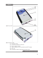
Figure 2
Device Scanner
Device
Controller
Storage batteries
Charging Unit of
Controller
(converter
≈220V/=24V)
Stray field’s record (magnetogram)
Object (VIN)
Surface
Magneto-optical
device (MOD)
Regula 7505M
Structural scheme of the device as a part of MOD
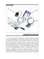
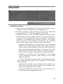
External view of the device controller with the basic controls
of indication and commutation is shown in Fig.3:
The device controller (Fig.3) is designed in the form of a printedwiring plate and is located in the metal body (pos.1). The controller
side slab has a socket for the connection of scanner (pos.2), and
ACC charging device (pos. 6) and its bottom side slab has ACC cells
(pos.5). The power supply tumbler (pos.3) and state indicators of the
controller and ACC charge (pos.4) are located on the front panel of
the controller body.
During the operation the device controller creates and sends voltage impulses with set parameters to the scanner. These parameters
correspond to the type of the connected scanner. Moreover, the controller carries out self-diagnostic, controls ACC charge and provides
its additional charge (if the ACC charging device is connected).
8