1
Distributed I/O
VersaMax Distributed I/O
VersaMax Distributed I/O
By choosing GE, customers gain access
to a complete line of highly versatile
and robust I/O modules that offer
seamless integration with the
PACSystems control family, for reliable,
high performance solutions.
The modular design of VersaMax I/O
addresses a wide range of discrete and
process applications. Its innovative
modular architecture combines power
and versatility to help provide performance in a compact control solution.
Power Supplies
Analog I/O Modules
Discrete I/O Modules
and complexity. These requirements
extend to the I/O that they use.
GE’s I/O solutions provide the high
performance control solutions with
best-in-class integration of distributed
(networked) I/O to meet these demanding applications.
Equipment builders are continuously
looking for ways to improve the
performance of their equipment while
augmenting usability and reducing size
pages 4.89-4.90
pages 4.104-4.108
pages 4.91-4.103
Network Interface Modules
Carriers
I/O Interposing Bases
The VersaMax PROFINET network
interface provides integrated I/O to
PACSystems controllers in both copper
and fiber interface. Ideal for any
remote I/O application, the PROFINET
interface supports ring topology, which
permits a node to go down or break
without transmission interruption.
page 4.114
pages 4.84-4.86
pages 4.87-4.88
Expansion Modules
page 4.111
RTD and Thermocouple Modules
page 4.109
Specialty Modules
page 4.110
Remote I/O Units
pages 4.112-4.113
Serial Communications
page 4.115
Accessories
Configuration Guidelines
page 4.116
pages 4.117-4.118
Publication Reference Chart
GFK-1179
Installation Requirements for Conformance to Standards
GFK-1697
VersaMax System AS-i Network Master Module User’s Manual
GFK-1503
VersaMax PLC User’s Manual
GFK-1847
Remote I/O Manager User’s Manual
GFK-1504
VersaMax Modules, Power Supplies, and Carriers User’s Manual
GFK-1852
VersaMax Serial to Ethernet Adapter User’s Manual
GFK-1533
VersaMax System DeviceNet Communications Modules User’s Manual
GFK-1860
VersaMax System Ethernet Network Interface Unit User’s Manual
GFK-1534
VersaMax System PROFIBUS Network Modules User’s Manual
GFK-1868
Proficy Machine Edition Getting Started Guide
GFK-1535
VersaMax System Genius Network Interface Unit User’s Manual
GFK-1876
VersaMax Ethernet Station Manager Manual
VersaMax I/O and Industrial Networking Application Guide
IC690CDU002 InfoLink for PLC CD-ROM
GFK-1563
www.ge-ip.com
GE Intelligent Platforms Control Systems Solutions
4.83
VersaMax Distributed I/O
Distributed I/O
Carriers
VersaMax provides several types of snap-together I/O carriers and interposing terminals
to provide maximum wiring flexibility, as well as module hot insertion and removal.
VersaMax carriers support IEC box-style, spring-style, and barrier-style terminals and are
also available as snap-on auxiliary terminal strips and interposing terminals that can be
mounted separately and connected to a connector-style carrier by an I/O cable.
IC200CHS022
IC200CHS025
Product Name
VersaMax Compact I/O Carrier,
Local Box Clamp Connection Style
VersaMax Compact I/O Carrier,
Local Spring Clamp Connection Style
Lifecycle Status
Active
Active
Field Termination Type
Integrated
Integrated
Wiring Termination Style
Local Box
Local Spring
Orientation on Module on Base
Dimensions (W x H x D)
Vertical
Vertical
66.8 mm (2.63 in) x 163.5 mm (6.45 in) x 70 mm (2.75 in),
not including the height of DIN-rail
66.8 mm (2.63 in) x 163.5 mm (6.45 in) x 70 mm (2.75 in),
not including the height of DIN-rail
N/A
N/A
Cables
4.84
GE Intelligent Platforms Control Systems Solutions
www.ge-ip.com
Distributed I/O
VersaMax Distributed I/O
Carriers
VersaMax provides several types of snap-together I/O carriers and interposing terminals to
provide maximum wiring flexibility, as well as module hot insertion and removal. VersaMax
carriers support IEC box-style, spring-style, and barrier-style terminals and are also available as snap-on auxiliary terminal strips and interposing terminals that can be mounted
separately and connected to a connector-style carrier by an I/O cable.
IC200CHS001
IC200CHS002
IC200CHS005
Product Name
VersaMax I/O Carrier,
Local Barrier Style
VersaMax I/O Carrier,
Local Box Style
VersaMax I/O Carrier,
Local Spring Clamp
Connection Style
Lifecycle Status
Active
Active
Active
Integrated
Integrated
Integrated
Barrier
Box
Spring
Horizontal
Horizontal
Horizontal
110.5 mm (4.35 in) x
139.7 mm (5.5 in) x
70 mm (2.75 in),
not including the
height of DIN-rail
110.5 mm (4.35 in) x
139.7 mm (5.5 in) x
70 mm (2.75 in),
not including the
height of DIN-rail
110.5 mm (4.35 in) x
139.7 mm (5.5 in) x
70 mm (2.75 in),
not including the
height of DIN-rail
N/A
N/A
N/A
Field Termination Type
Wiring Termination Style
Orientation on Module on Base
Dimensions (W x H x D)
Cables
www.ge-ip.com
GE Intelligent Platforms Control Systems Solutions
4.85
VersaMax Distributed I/O
Distributed I/O
Carriers
VersaMax provides several types of snap-together I/O carriers and interposing
terminals to provide maximum wiring flexibility, as well as module hot insertion
and removal. VersaMax carriers support IEC box-style, spring-style, and barrierstyle terminals and are also available as snap-on auxiliary terminal strips and
interposing terminals that can be mounted separately and connected to a
connector-style carrier by an I/O cable.
IC200CHS003
IC200CHS011
IC200CHS012
IC200CHS014
IC200CHS015
VersaMax I/O Carrier,
Interposing Box Style
(Requires IC200CHS003
base and connecting
cable IC200CBL1xxx)
VersaMax I/O Carrier,
Interposing Box
Thermocouple
Compensation
(Requires IC200CHS003
base and connecting
cable IC200CBL1xxx)
VersaMax I/O Carrier,
Interposing Spring Clamp
(Requires IC200CHS003
base and connecting
cable IC200CBL1xxx)
VersaMax I/O Carrier,
Interposing Spring Clamp
(Requires IC200CHS003
base and connecting
cable IC200CBL1xxx)
Product Name
VersaMax I/O Carrier,
VersaMax I/O Carrier,
Connector Style. Interposing
Barrier A connecting cable Style
(Requires (IC200CBL1xxx) and
IC200CHS003 base interposing
base (IC200CHS011, and
connecting CHS012, CHS014,
CHS015, cable IC200CBL1xxx)
IC200CHS1xx or IC200CHS2xx)
are required. This carrier can be
used with all VersaMax I/O
modules EXCEPT the following,
due to their high isolation
requirements: IC200MDL144
Input 240 VAC 4 Point Isolated
Module; IC200MDL244 Input 240
VAC 8 Point Isolated Module;
IC200MDD850 Mixed 240 VAC
Isolated 4 Point / Output Relay
2.0A Isolated 8 Point Module
Lifecycle Status
Active
Active
Active
Active
Active
Integrated
Non-Integrated
Non-Integrated
Integrated
Non-Integrated
Connector
Barrier
Box
Box-Thermocouple
Compensation
Spring
Vertical
N/A
N/A
N/A
N/A
Dimensions (W x H x D)
66.8 mm (2.63 in) x
133.4 mm (5.25 in) x
70 mm (2.75 in),
not including the
height of DIN-rail
110.5 mm (4.35 in) x
105.4 mm (2.63 in) x
70 mm (2.75 in),
not including the
height of DIN-rail
110.5 mm (4.35 in) x
105.4 mm (2.63 in) x
70 mm (2.75 in),
not including the
height of DIN-rail
110.5 mm (4.35 in) x
105.4 mm (2.63 in) x
70 mm (2.75 in),
not including the
height of DIN-rail
110.5 mm (4.35 in) x
105.4 mm (2.63in) x
70 mm (2.75 in),
not including the
height of DIN-rail
Cables
Requires a
IC200CBL1xxx cable
Requires a
IC200CBL1xxx cable
Requires a
IC200CBL1xxx cable
Requires a
IC200CBL1xxx cable
Requires a
IC200CBL1xxx cable
Field Termination Type
Wiring Termination Style
Orientation on
Module on Base
4.86
GE Intelligent Platforms Control Systems Solutions
www.ge-ip.com
Distributed I/O
VersaMax Distributed I/O
I/O Interposing Bases
VersaMax I/O interposing disconnect bases enable the IC200CHS003 to connect to a
wide range of termination bases. The Relay bases provide additional protection and
higher amperage outputs. The Disconnect bases enables the user to easily disconnect
signals, on a per point bases, from the I/O module.
IC200CHS003
IC200CHS101
IC200CHS102
IC200CHS111
Product Name
VersaMax I/O Carrier,
Connector Style.
A connecting cable
(IC200CBL1xxx) and
interposing base
(IC200CHS011, CHS012,
CHS014, CHS015, IC200CHS1xx
or IC200CHS2xx) are required.
This carrier can be used with
all VersaMax I/O modules
EXCEPT the following, due
to their high isolation
requirements: IC200MDL144
Input 240 VAC 4 Point Isolated
Module; IC200MDL244 Input
240 VAC 8 Point Isolated
Module; IC200MDD850
Mixed 240 VAC Isolated
4 Point / Output Relay 2.0A
Isolated 8 Point Module
Input or Output Interposing
Disconnect Style 16 Points.
The base has an individual
knife-switch disconnect
for each signal and common
terminal and its corresponding
pin on the VersaMax cable
connector. Requires
IC200CHS003 and a connecting
cable IC200CBL1xxx.
Expansion Input or Output
Interposing Disconnect Style
16 Points. The base has an
individual knife-switch
disconnect for each signal
and common terminal and
its corresponding pin on the
VersaMax cable connector.
Requires a IC200CHS101 main
base, can not be directly
connected to IC200CHS003.
I/O Interposing Relay Base
(replaceable relays), fused
(8 amps, replaceable), 16 points.
The relays on these interposing
terminals are intended to
be controlled with standard
24 VDC 0.5A VersaMax output
modules (IC200MDL740 and
IC200MDL750 using
IC200CHS003 base and
connected by IC200CBL1xxx).
Lifecycle Status
Active
Active
Active
Active
Field Termination Type
Integrated
Non-Integrated
Non-Integrated
Non-Integrated
Wiring Termination Style
Connector
Box
Box
Box
Removable Terminals Connectors
N/A
No
No
No
N/A
All discrete modules supported
except MDL144, 244, 331, 730
and MDD840, 843, 850.
All discrete modules supported
except MDL144, 244, 331, 730
and MDD840, 843, 850.
24 VDC from MDL740
and MDL750
N/A
All discrete modules supported
except MDL144, 244, 331, 730
and MDD840, 843, 850.
All discrete modules supported
except MDL144, 244, 331, 730
and MDD840, 843, 850.
0-125 VDC, 5/24/125 VDC
nominal; 0-265 VAC (47-63 Hz),
120/240 VAC nominal
N/A
N/A
N/A
8.0 A for 5-265 VAC,
2.0 A for 5-30 VDC,
0.2 A for 31-125 VDC
(Replaceable Fuse)
N/A
N/A
N/A
Replaceable Fuse
Input Voltage
Output Voltage
Load Current per Point
Protection
Points per Common
Dimensions (W x H x D)
Cables
www.ge-ip.com
N/A
N/A
N/A
Isolated Per Point
66.8 mm (2.63 in) x 133.4 mm
(5.25 in) x 70 mm (2.75 in),
not including the
height of the DIN-rail
115 mm (4.5 in) x 126 mm
(4.95 in) x 65 mm (2.6 in),
not including the
height of the DIN-rail
115 mm (4.5 in) x 126 mm
(4.95 in) x 65 mm (2.6 in),
not including the
height of the DIN-rail
253.7 mm (9.9 in) x 126 mm
(4.95 in) x 73 mm (2.8 in),
not including the
height of the DIN-rail
Requires a
IC200CBL1xxx cable
Requires a
IC200CBL1xxx cable
N/A
Requires a
IC200CBL1xxx cable
GE Intelligent Platforms Control Systems Solutions
4.87
VersaMax Distributed I/O
Distributed I/O
I/O Interposing Bases
VersaMax I/O interposing disconnect bases enable the IC200CHS003 to connect to a
wide range of termination bases. The Relay bases provide additional protection and
higher amperage outputs. The Disconnect bases enables the user to easily disconnect
signals, on a per point bases, from the I/O module.
IC200CHS112
IC200CHS211
IC200CHS212
I/O Interposing Relay Base
(replaceable relays), fused
(8 amps, replaceable), 16 points.
The relays on these interposing
terminals are intended to be
controlled with standard 24 VDC
0.5A VersaMax output modules
(IC200MDL740 and IC200MDL750
using IC200CHS003 base and
connected by IC200CBL1xxx).
Expansion base.
I/O Interposing Relay Base
(replaceable relays), fused
(8 amps, replaceable), 16 points.
Field terminals are removable.
The relays on these interposing
terminals are intended to be
controlled with standard 24 VDC
0.5A VersaMax output modules
(IC200MDL740 and IC200MDL750
using IC200CHS003 base and
connected by IC200CBL1xxx).
Expansion base.
Active
Active
Active
Non-Integrated
Non-Integrated
Non-Integrated
Connection Style
Box
Box
Box
Removable Terminals Connectors
No
Yes
Yes
24 VDC from MDL740
and MDL750
24 VDC from MDL740
and MDL750
24 VDC from MDL740
and MDL750
0-125 VDC, 5/24/125 VDC nominal;
0-265 VAC (47-63 Hz),
120/240 VAC nominal
0-125 VDC, 5/24/125 VDC nominal;
0-265 VAC (47-63 Hz),
120/240 VAC nominal
0-125 VDC, 5/24/125 VDC nominal;
0-265 VAC (47-63 Hz),
120/240 VAC nominal
8.0 A for 5-265 VAC, 2.0 A for 5-30 VDC, 0.2
A for 31-125 VDC (Replaceable Fuse)
8.0 A for 5-265 VAC, 2.0 A for 5-30 VDC, 0.2
A for 31-125 VDC (Replaceable Fuse)
8.0 A for 5-265 VAC, 2.0 A for 5-30 VDC, 0.2
A for 31-125 VDC (Replaceable Fuse)
Protection
Replaceable Fuse
Replaceable Fuse
Replaceable Fuse
Points per Common
Isolated Per Point
Isolated Per Point
Isolated Per Point
253.7 mm (9.9 in) x 126 mm (4.95 in) x 73
mm (2.8 in), not including the height of the
DIN-rail
253.7 mm (9.9 in) x 126 mm (4.95 in) x 73
mm (2.8 in), not including the height of the
DIN-rail
253.7 mm (9.9 in) x 126 mm (4.95 in) x 73
mm (2.8 in), not including the height of the
DIN-rail
N/A
Requires a
IC200CBL1xxx cable
N/A
Product Name
Lifecycle Status
Field Termination Type
Input Voltage
Output Voltage
Load Current per Point
Dimensions (W x H x D)
Cables
4.88
GE Intelligent Platforms Control Systems Solutions
www.ge-ip.com
Distributed I/O
VersaMax Distributed I/O
Power Supplies
VersaMax Power Supply modules snap onto any VersaMax CPU or Network Interface Unit or
onto a power supply booster carrier. Each power supply can be used as the main power
source for modules in the I/O station, or as a source of supplemental power for larger I/O
applications.
IC200PWR001
IC200PWR002
IC200PWR011
IC200PWR012
IC200PWR101
24 VDC Power Supply
24 VDC Power Supply
with Expanded 3.3 V
24VDC Isolated
Power Supply
24VDC Isolated
Power Supply with
Expanded 3.3 V
120/240 VAC
Power Supply
Lifecycle Status
Active
Active
Active
Active
Active
Input Voltage
24 VDC
24 VDC
24 VDC
24 VDC
120/240 VAC
Output Voltage
5 VDC, 3.3 VDC
5 VDC, 3.3 VDC
5 VDC, 3.3 VDC
5 VDC, 3.3 VDC
5 VDC, 3.3 VDC
Extended Power
No
Yes
No
Yes
No
11 W
11 W
11 W
11 W
27 VA
No
No
Yes
Yes
N/A
Product Name
Input Power
Isolated Power
Holdup Time
Inrush Current
Protection
Total Output Current
3.3V Output Current
5V Output Current
Dimensions (W x H x D)
www.ge-ip.com
10 ms
10 ms
10 ms
10 ms
20 ms
20 A @ 24 VDC;
25 A @ 30 VDC
20 A @ 24 VDC;
25 A @ 30 VDC
20 A @ 24 VDC;
25 A @ 30 VDC
20 A @ 24 VDC;
25 A @ 30 VDC
N/A
Short circuit, overload,
reverse polarity
Short circuit, overload,
reverse polarity
Short circuit, overload,
reverse polarity
Short circuit, overload,
reverse polarity
Short circuit, overload
1.5 A maximum
1.5 A maximum
1.5 A maximum
1.5 A maximum
1.5 A maximum
0.25 A maximum
1.0 A maximum
0.25 A maximum
1.0 A maximum
0.25 A maximum
1.5 A minus the 3.3 V
current used, maximum
1.5 A minus the 3.3 V
current used, maximum
1.5 A minus the 3.3 V
current used, maximum
1.5 A minus the 3.3 V
current used, maximum
1.5 A minus the 3.3 V
current used, maximum
49 mm (1.93 in) x
133.4 mm (5.25 in) x
39 mm (1.54 in),
not including the
height of the carrier
or the DIN-rail
49 mm (1.93 in) x
133.4 mm (5.25 in) x
39 mm (1.54 in),
not including the
height of the carrier
or the DIN-rail
49 mm (1.93 in) x
133.4 mm (5.25 in) x
39 mm (1.54 in),
not including the
height of the carrier
or the DIN-rail
49 mm (1.93 in) x
133.4 mm (5.25 in) x
39 mm (1.54 in),
not including the
height of the carrier
or the DIN-rail
49 mm (1.93 in) x
133.4 mm (5.25 in) x
39 mm (1.54 in),
not including the
height of the carrier
or the DIN-rail
GE Intelligent Platforms Control Systems Solutions
4.89
VersaMax Distributed I/O
Distributed I/O
Power Supplies
VersaMax Power Supply modules snap onto any VersaMax CPU or Network Interface Unit or
onto a power supply booster carrier. Each power supply can be used as the main power
source for modules in the I/O station, or as a source of supplemental power for larger I/O
applications.
IC200PWR102
IC200PWR201
IC200PWR202
IC200PWB001
120/240 VAC Power Supply
with Expanded 3.3 VDC
12 VDC Power Supply
12 VDC Power Supply
with Expanded 3.3 VDC
VersaMax Power Supply
Booster Carrier.
Supplies power to all
modules to the right
of booster. Requires
power supply.
Active
Active
Active
Active
120/240 VAC
9.6-15 VDC, 12 VDC nominal
9.6-15 VDC, 12 VDC nominal
N/A
Output Voltage
5 VDC, 3.3 VDC
5 VDC, 3.3 VDC
5 VDC, 3.3 VDC
N/A
Extended Power
Yes
No
Yes
N/A
27 VA
11 W
11 W
N/A
N/A
No
No
N/A
Product Name
Lifecycle Status
Input Voltage
Input Power
Isolated Power
Holdup Time
Inrush Current
Protection
Total Output Current
3.3V Output Current
5V Output Current
Dimensions (W x H x D)
4.90
20 ms
10 ms
10 ms
N/A
N/A
25 A at 12 VDC; 30 A at 15 VDC
25 A at 12 VDC; 30 A at 15 VDC
N/A
Short circuit, overload
Short circuit, overload,
reverse polarity
Short circuit, overload,
reverse polarity
N/A
1.5 A maximum
1.5 A maximum
1.5 A maximum
N/A
1.0 A maximum
0.25 A maximum
1.0 A maximum
N/A
1.5 A minus the 3.3 V
current used, maximum
1.5 A minus the 3.3 V
current used, maximum
1.5 A minus the 3.3 V
current used, maximum
N/A
49 mm (1.93 in) x
133.4 mm (5.25 in) x
39 mm (1.54 in),
not including the
height of the carrier
or the DIN-rail
49 mm (1.93 in) x
133.4 mm (5.25 in) x
39 mm (1.54 in),
not including the
height of the carrier
or the DIN-rail
49 mm (1.93 in) x
133.4 mm (5.25 in) x
39 mm (1.54 in),
not including the
height of the carrier
or the DIN-rail
66.8 mm (2.63 in) x
133.4 mm (5.25 in) x
70 mm (2.75 in),
not including the
height of DIN-rail
GE Intelligent Platforms Control Systems Solutions
www.ge-ip.com
Distributed I/O
VersaMax Distributed I/O
Discrete Mixed I/O Modules
Discrete mixed modules provide maximum flexibility by combining inputs and outputs in a single,
compact module. Discrete input modules receive signals from input devices such as sensors, pushQdcc^]bP]SbfXcRWTbcWPcRP]WPeTcf^bcPcTb)^]^a^UU^_T]^aR[^bTS3XbRaTcT^dc_dc\^Sd[Tb
send control signals to devices such as contactors, indicator lamps, and interposing relays that can
also have two states. Discrete mixed modules provide maximum flexibility by combining inputs and
outputs in a single, compact module. Modules require a carrier base (IC200CHSxxx).
IC200MDD840
IC200MDD842
IC200MDD843
Product Name
VersaMax Discrete Mixed Modules,
24 VDC Pos Logic Input 20 points/Output
Relay 2.0 A, 12 points
VersaMax Discrete Mixed Modules
24 VDC Pos Logic Input 16/Output
24 VDC 0.5 A with ESCP
VersaMax Discrete Mixed Modules
24 VDC Positive Logic Input
10/Output Relay 6
Lifecycle Status
Active
Active
Active
Input Voltage
24 VDC
24 VDC
24 VDC
0-125 VDC, 5/24/125 VDC nominal;
0-265 VAC (47-63 Hz),
120/240 VAC nominal
24 VDC
0-125 VDC, 5/24/125 VDC nominal;
0-265 VAC (47-63 Hz),
120/240 VAC nominal
20 in/12 out
16 in/16 out
10 in/6 out
No
No
No
2.0 A for 5-265 VAC, 2.0 A for 5-30 VDC
0.5 A for 30 VDC
2.0 A for 5-265 VAC, 2.0 A for 5-30 VDC, 0.2
A for 31-125 VDC
0.5 and 10
0.5 and 0.5
0.5 and 10
No internal fuses or snubbers
Short circuit protection, overcurrent
protection, free-wheeling diodes
No internal fuses or snubbers
On State Current
2.0-5.5 mA
2.0-5.5 mA
2.0-5.5 mA
Off State Current
0-0.5 mA
0-0.5 mA
0-0.5 mA
0-125 VDC, 5/24/125 VDC nominal; 0-265
VAC (47-63 Hz), 120/240 VAC nominal
18-30 VDC, 24 VDC nominal
0-125 VDC, 5/24/125 VDC nominal, 0-265
VAC (47-63 Hz), 120/240 VAC nominal
10 kOhms maximum
10 kOhms maximum
10 kOhms maximum
2.0 A for 5-265 VAC or
5-30 VDC, 0.2 A for 31-125 VDC
0.5 Amp at 30 VDC
maximum (resistive);
2.0 Amps maximum for
100ms inrush
10 mA per point minimum,
8.0 A maximum per module;
2.0 Amps for 5 to 265 VAC
maximum (resistive);
2.0 Amps for 5 to 30 VDC
maximum (resistive);
0.2 Amp for 31 to 125 VDC
maximum (resistive)
375 maximum
100 maximum
190 maximum
LED Indicators
One LED per point shows individual
point on/off state (logic side); OK LED
indicates backplane power is present
One LED per point shows individual
point on/off state (logic side); OK LED
indicates backplane power is present
One LED per point shows individual
point on/off state (logic side); OK LED
indicates backplane power is present
Dimensions (W x H x D)
110 mm (4.3 in) x 66.8 mm (2.63 in) x
50 mm (1.956 in), not including the
height of the carrier or the
mating connectors
110 mm (4.3 in) x 66.8 mm (2.63 in) x
50 mm (1.956 in), not including the
height of the carrier or the
mating connectors
110 mm (4.3 in) x 66.8 mm (2.63 in) x
50 mm (1.956 in), not including the
height of the carrier or the
mating connectors
Output Voltage
Number of Points
Channel to Channel Isolation
Load Current per Point
Input and Output Response
Time- On/Off(ms)
Protection
External Power Supply
Input Impedance
Load Current
5V Backplane Current
Consumption (mA)
www.ge-ip.com
GE Intelligent Platforms Control Systems Solutions
4.91
VersaMax Distributed I/O
Distributed I/O
Discrete Mixed I/O Modules
Discrete mixed modules provide maximum flexibility by combining inputs and outputs in a single,
compact module. Discrete input modules receive signals from input devices such as sensors, pushQdcc^]bP]SbfXcRWTbcWPcRP]WPeTcf^bcPcTb)^]^a^UU^_T]^aR[^bTS3XbRaTcT^dc_dc\^Sd[Tb
send control signals to devices such as contactors, indicator lamps, and interposing relays that can
also have two states. Discrete mixed modules provide maximum flexibility by combining inputs and
outputs in a single, compact module. Modules require a carrier base (IC200CHSxxx).
IC200MDD844
IC200MDD845
IC200MDD846
Product Name
VersaMax Discrete Mixed
Modules 24 VDC Positive Logic
Input 16/Output 24 VDC 0.5 A 16 points
VersaMax Discrete Mixed
Modules 24 VDC Positive Logic Input
16/Output Relay 2.0A Isolated 8 points
VersaMax Discrete Mixed Modules
120 VAC Input 8 points/Outpoints
Relay 2.0A Isolated 8 points
Lifecycle Status
Active
Active
Active
Input Voltage
24 VDC
24 VDC
120 VAC
24 VDC
0-125 VDC, 5/24/125 VDC nominal;
0-265 VAC (47-63 Hz),
120/240 VAC nominal
0-125 VDC, 5/24/125 VDC nominal;
0-265 VAC (47-63 Hz),
120/240 VAC nominal
16 in/16 out
16 in/8 out
8 in/8 out
No
Yes, outputs
Yes, outputs
0.5 A for 30 VDC
2.0 A for 5-265 VAC, 2.0 A for 5-30 VDC,
0.2 A for 31-125 VDC
2.0 A for 5-265 VAC, 2.0 A for 5-30 VDC,
0.2 A for 31-125 VDC
0.5 and 0.2 ON / 1.0 OFF
0.5 and 10
1 AC cycle minimum and 2 AC cycle
(Hz dependent) maximum and 10.0 OFF
No internal fuses
No internal fuses or snubbers
No internal fuses or snubbers
On State Current
2.0-5.5 mA
2.0-5.5 mA
5 mA minimum
Off State Current
0-0.5 mA
0-0.5 mA
2.5 mA maximum
Output Voltage
Number of Points
Channel to Channel Isolation
Load Current per Point
Input and Output Response
Time- On/Off(ms)
Protection
External Power Supply
Input Impedance
18-30 VDC, 24 VDC nominal
10 kOhms maximum
0.5 Amp at 30 VDC maximum (resistive) 2.0
Amps maximum for 100ms inrush
Load Current
5V Backplane Current
Consumption (mA)
0-125 VDC, 5/24/125 VDC nominal;
0-125 VDC, 5/24/125 VDC nominal;
0-265 VAC (47-63 Hz), 120/240 VAC nominal 0-265 VAC (47-63 Hz), 120/240 VAC nominal
10 kOhms maximum
8.6 kOhms (reactive) at 60 Hz, typical;
10.32 kOhms (reactive) at 50 Hz, typical
10 mA per point minimum
10 mA per point minimum
2.0 A for 5 to 265 VAC maximum (resistive) 2.0 A for 5 to 265 VAC maximum (resistive)
2.0 A for 5 to 30 VDC maximum (resistive)
2.0 A for 5 to 30 VDC maximum (resistive)
0.2 A for 31 to 125 VDC maximum (resistive) 0.2 A for 31 to 125 VDC maximum (resistive)
70 maximum
270 maximum
300 maximum
LED Indicators
One LED per point shows individual
point on/off state (logic side); OK LED
indicates backplane power is present
One LED per point shows individual
point on/off state (logic side); OK LED
indicates backplane power is present
One LED per point shows individual
point on/off state (logic side); OK LED
indicates backplane power is present
Dimensions (W x H x D)
110 mm (4.3 in) x 66.8 mm (2.63 in) x
50 mm (1.956 in), not including the
height of the carrier or the
mating connectors
110 mm (4.3 in) x 66.8 mm (2.63 in) x
50 mm (1.956 in), not including the
height of the carrier or the
mating connectors
110 mm (4.3 in) x 66.8 mm (2.63 in) x
50 mm (1.956 in), not including the
height of the carrier or the
mating connectors
4.92
GE Intelligent Platforms Control Systems Solutions
www.ge-ip.com
Distributed I/O
VersaMax Distributed I/O
Discrete Mixed I/O Modules
Discrete mixed modules provide maximum flexibility by combining inputs and outputs in a single,
compact module. Discrete input modules receive signals from input devices such as sensors, pushQdcc^]bP]SbfXcRWTbcWPcRP]WPeTcf^bcPcTb)^]^a^UU^_T]^aR[^bTS3XbRaTcT^dc_dc\^Sd[Tb
send control signals to devices such as contactors, indicator lamps, and interposing relays that can
also have two states. Discrete mixed modules provide maximum flexibility by combining inputs and
outputs in a single, compact module. Modules require a carrier base (IC200CHSxxx).
IC200MDD847
IC200MDD848
IC200MDD849
Product Name
VersaMax Discrete Mixed Modules
240 VAC Input 8 points/Output Relay
2.0A Isolated 8 points
VersaMax Discrete Mixed Modules
120 VAC Input 8 points/Output
120 VAC 0.5A Isolated 8 points
VersaMax Discrete Mixed Modules
120 VAC Input Isolated 8 points/Output
Relay 2.0 A Isolated 8 points
Lifecycle Status
Active
Active
Active
240 VAC
120 VAC
0-132 VAC (47 to 63 Hz), 120 VAC nominal
0-125 VDC, 5/24/125 VDC nominal;
0-265 VAC (47-63 Hz),
120/240 VAC nominal
120 VAC
0-125 VDC, 5/24/125 VDC nominal;
0-265 VAC (47-63 Hz),
120/240 VAC nominal
8 in/8 out
8 in/8 out
8 in/8 out
Yes, outputs
Yes
Yes
Load Current per Point
2.0 A for 5-265 VAC, 2.0 A for 5-30 VDC,
0.2 A for 31-125 VDC
10 mA min, 0.5 A max., 5 A for 1 cycle
(20 ms) max. inrush
2.0 A
Input and Output Response
Time- On/Off(ms)
1 AC cycle minimum and 2 AC cycle
(Hz dependent) maximum and 10.0 OFF
1 cycle/2 cycle and
<1/2 cycle/<1/2 cycle
1 cycle/2 cycle and
10/10
No internal fuses or snubbers
Snubber and MOVs (each output)
No internal fuses or snubbers
On State Current
4 mA minimum
5 mA minimum
5 mA minimum
Off State Current
1.5 mA maximum
2.5 mA maximum
2.5 mA maximum
0-125 VDC, 5/24/125 VDC nominal;
0-265 VAC (47-63 Hz), 120/240 VAC nominal
0-125 VDC, 5/24/125 VDC nominal;
0-265 VAC (47-63 Hz), 120/240 VAC nominal
N/A
38.5 kOhms (reactive) at 60 Hz, typical;
46.3 kOhms (reactive) at 50 Hz, typical
8.6 kOhms (reactive) at 60 Hz, typical;
10.32 kOhms (reactive) at 50 Hz, typical
8.6 kOhms (reactive) at 60 Hz, typical;
10.32 kOhms (reactive) at 50 Hz, typical
10 mA per point minimum
2.0 Amps for 5 to 265 VAC maximum (resistive)
2.0 Amps for 5 to 30 VDC maximum (resistive)
0.2 Amp for 31 to 125 VDC maximum (resistive)
10 mA minimum per point,
0.5 A maximum per point, 5.0 A for
one cycle (20 ms) maximum inrush
10 mA per point minimum;
2.0 A for 5-265 VAC maximum (resistive);
2.0 A for 5-30 VDC maximum (resistive);
0.2 A for 31-125 VDC maximum (resistive)
300 maximum
125 maximum
300 maximum
One LED per point shows individual point
on/off state (logic side); OK LED indicates
backplane power is present
One LED per point shows individual point
on/off state (logic side); OK LED indicates
backplane power is present
One LED per point shows individual point
on/off state (logic side); OK LED indicates
backplane power is present
110 mm (4.3 in) x 66.8 mm (2.63 in) x
50 mm (1.956 in), not including the
height of the carrier or the
mating connectors
110 mm (4.3 in) x 66.8 mm (2.63 in) x
50 mm (1.956 in), not including the
height of the carrier or the
mating connectors
110 mm (4.3 in) x 66.8 mm (2.63 in) x
50 mm 1.956 in), not including the
height of (the carrier or the
mating connectors
Input Voltage
Output Voltage
Number of Points
Channel to Channel Isolation
Protection
External Power Supply
Input Impedance
Load Current
5V Backplane Current
Consumption (mA)
LED Indicators
Dimensions (W x H x D)
www.ge-ip.com
GE Intelligent Platforms Control Systems Solutions
4.93
VersaMax Distributed I/O
Distributed I/O
Discrete Mixed I/O Modules
Discrete mixed modules provide maximum flexibility by combining inputs and outputs in a single,
compact module. Discrete input modules receive signals from input devices such as sensors, pushQdcc^]bP]SbfXcRWTbcWPcRP]WPeTcf^bcPcTb)^]^a^UU^_T]^aR[^bTS3XbRaTcT^dc_dc\^Sd[Tb
send control signals to devices such as contactors, indicator lamps, and interposing relays that can
also have two states. Discrete mixed modules provide maximum flexibility by combining inputs and
outputs in a single, compact module. Modules require a carrier base (IC200CHSxxx).
IC200MDD850
IC200MDD851
Product Name
VersaMax Discrete Mixed Modules
240 VAC Input Isolated 4 points/Output
Relay 2.0 A Isolated 8 points
VersaMax Discrete Mixed Modules
5/12 VDC Input 16 points/Output
12/24 VDC 16 points
Lifecycle Status
Active
Active
0-264 VAC (47-63 Hz), 240 VAC nominal
0 to 15 VDC, +5/12 VDC nominal
0-125 VDC, 5/24/125 VDC nominal;
0-265 VAC (47-63 Hz),
120/240 VAC nominal
+10.2 to +30 VDC, +12/24 VDC nominal
8 out/4 in
16 out/16 in
Yes
No
2.0 A
0.5 Amps at 30 VDC maximum (resistive)
2.0 Amps maximum for 100ms inrush
1 cycle/2 cycle
and 10/10
0.25ms maximum/0.2ms ON
and 1.0ms OFF maximum
No internal fuses or snubbers
No internal fuses or snubbers
On State Current
4 mA minimum
1.45 mA minimum
Off State Current
1.5 mA maximum
0 to 0.7 mA maximum
N/A
+10.2 to +30 VDC, +12/24 VDC nominal
38.5 kOhms (reactive) at 60 Hz, typical;
46.3 kOhms (reactive) at 50 Hz, typical
2.4kOhms typical @ 12 VDC
10 mA per point minimum;
2.0 A for 5-265 VAC maximum (resistive);
2.0 A for 5-30 VDC maximum (resistive);
0.2 A for 31-125 VDC maximum (resistive)
0.5 Amps at 30 VDC maximum (resistive);
2.0 Amps maximum for 100ms inrush
260 maximum
115 maximum
One LED per point shows individual point
on/off state logic side); OK LED indicates
backplane power is present
One LED per point shows individual point
on/off state (logic side); OK LED indicates
backplane power is present
110 mm (4.3 in) x 66.8 mm (2.63 in) x
50 mm (1.956 in), not including the
height of the carrier or the
mating connectors
110 mm (4.3 in) x 66.8 mm (2.63 in) x
50 mm (1.956 in), not including the
height of the carrier or the
mating connectors
Input Voltage
Output Voltage
Number of Points
Channel to Channel Isolation
Load Current per Point
Input and Output Response
Time- On/Off(ms)
Protection
External Power Supply
Input Impedance
Load Current
5V Backplane Current
Consumption (mA)
LED Indicators
Dimensions (W x H x D)
4.94
GE Intelligent Platforms Control Systems Solutions
www.ge-ip.com
Distributed I/O
VersaMax Distributed I/O
Discrete Input Modules
Discrete input modules receive signals from input devices such as sensors, pushbuttons, and
bfXcRWTbcWPcRP]WPeTcf^bcPcTb)^]^a^UU^_T]^aR[^bTS<^Sd[TbaT`dXaTPRPaaXTaQPbT
(IC200CHSxxx).
IC200MDL140
IC200MDL141
IC200MDL143
Product Name
VersaMax Discrete Input
Module 120 VAC,
8 points
VersaMax Discrete Input
Module 240 VAC,
8 points
VersaMax Discrete Input
Module 120 VAC Isolated,
8 points
Lifecycle Status
Active
Active
Active
0-132 VAC
0-264 VAC
0-132 VAC
8
8
8
No
No
Yes
1 cycle/2 cycles
1 cycle/2 cycles
1 cycle/2 cycles
1 group of 8
1 group of 8
8 groups of 1
On State Current
5 mA minimum
7 mA minimum
5 mA minimum
Off State Current
2.5 mA maximum
1.5 mA maximum
2.5 mA maximum
Input Impedance
8.6 kOhms (reactive) at 60 Hz, typical;
10.32 kOhms (reactive) at 50 Hz, typical
38.5 kOhms (reactive) at 60 Hz, typical;
46.3 kOhms (reactive) at 50 Hz, typical
8.6 kOhms (reactive) at 60 Hz, typical;
10.32 kOhms (reactive) at 50 Hz, typical
55 maximum
55 maximum
50 maximum
One LED per point shows
individual point ON/OFF status.
OK LED indicates backplane
power is present
One LED per point shows
individual point ON/OFF status.
OK LED indicates backplane
power is present
One LED per point shows
individual point ON/OFF status.
OK LED indicates backplane
power is present
110 mm (4.3 in) x 66.8 mm (2.63 in) x
50 mm (1.956 in), not including the
height of the carrier or the
mating connectors
110 mm (4.3 in) x 66.8 mm (2.63 in) x
50 mm (1.956 in), not including the
height of the carrier or the
mating connectors
110 mm (4.3 in) x 66.8 mm (2.63 in) x
50 mm (1.956 in), not including the
height of the carrier or the
mating connectors
Input Voltage
Number of Points
Channel to Channel Isolation
Input and Output Response
Time- On/Off (ms)
Points per Common
5V Backplane Current
Consumption (mA)
LED Indicators
Dimensions (W x H x D)
www.ge-ip.com
GE Intelligent Platforms Control Systems Solutions
4.95
VersaMax Distributed I/O
Distributed I/O
Discrete Input Modules
Discrete input modules receive signals from input devices such as sensors, pushbuttons, and
bfXcRWTbcWPcRP]WPeTcf^bcPcTb)^]^a^UU^_T]^aR[^bTS<^Sd[TbaT`dXaTPRPaaXTaQPbT
(IC200CHSxxx).
IC200MDL144
IC200MDL240
IC200MDL241
Product Name
VersaMax Discrete Input
Module 240 VAC Isolated,
4 points
VersaMax Discrete Input
Module, 120 VAC Positive Logic,
16 points
VersaMax Discrete Input
Module, 240 VAC Positive Logic,
16 points
Lifecycle Status
Active
Active
Active
0-264 VAC
0-132 VAC
0-264 VAC
4
16
16
Yes
No
No
1 cycle/2 cycles
1 cycle/2 cycles
1 cycle/2 cycles
4 groups of 1
2 groups of 8
2 groups of 8
On State Current
7 mA minimum
5 mA minimum
4 mA minimum
Off State Current
3 mA maximum
2.5 mA maximum
1.5 mA maximum
Input Impedance
38.5 kOhms (reactive) at 60 Hz, typical;
46.3 kOhms (reactive) at 50 Hz, typical
8.6 kOhms (reactive) at 60 Hz, typical;
10.32 kOhms (reactive) at 50 Hz, typical
38.5 kOhms (reactive) at 60 Hz, typical;
46.3 kOhms (reactive) at 50 Hz, typical
30 maximum
110 maximum
110 maximum
One LED per point shows
individual point ON/OFF status.
OK LED indicates backplane
power is present
One LED per point shows
individual point ON/OFF status.
OK LED indicates backplane
power is present
One LED per point shows
individual point ON/OFF status.
OK LED indicates backplane
power is present
110 mm (4.3 in) x 66.8 mm (2.63 in) x
50 mm (1.956 in), not including the
height of the carrier or the
mating connectors
110 mm (4.3 in) x 66.8 mm (2.63 in) x
50 mm (1.956 in), not including the
height of the carrier or the
mating connectors
110 mm (4.3 in) x 66.8 mm (2.63 in) x
50 mm (1.956 in), not including the
height of the carrier or the
mating connectors
Input Voltage
Number of Points
Channel to Channel Isolation
Input and Output Response
Time- On/Off (ms)
Points per Common
5V Backplane Current
Consumption (mA)
LED Indicators
Dimensions (W x H x D)
4.96
GE Intelligent Platforms Control Systems Solutions
www.ge-ip.com
Distributed I/O
VersaMax Distributed I/O
Discrete Input Modules
Discrete input modules receive signals from input devices such as sensors, pushbuttons, and
bfXcRWTbcWPcRP]WPeTcf^bcPcTb)^]^a^UU^_T]^aR[^bTS<^Sd[TbaT`dXaTPRPaaXTaQPbT
(IC200CHSxxx).
IC200MDL243
IC200MDL244
IC200MDL631
Product Name
VersaMax Discrete Input
Module, 120 VAC Isolated,
16 points
VersaMax Discrete Input
Module, 240 VAC Isolated,
8 points
VersaMax Discrete Input
Module 125 VDC, Pos/Neg Logic,
Isolated, 8 points
Lifecycle Status
Active
Active
Active
0-132 VAC
0-264 VAC
0-150 VDC, 125 VDC nominal
Number of Points
16
8
8 isolated inputs
Channel to Channel Isolation
Input Voltage
Yes
Yes
Yes
Input and Output Response
Time- On/Off (ms)
1 cycle/2 cycles
1 cycle/2 cycles
0.5 maximum
Points per Common
16 groups of 1
8 groups of 1
8 groups of 1
On State Current
5 mA minimum
7 mA minimum
1.0 mA minimum
Off State Current
2.5 mA maximum
3 mA maximum
0 to 0.1 mA maximum
Input Impedance
8.6 kOhms (reactive) at 60 Hz, typical;
10.32 kOhms (reactive) at 50 Hz, typical
38.5 kOhms (reactive) at 60 Hz, typical;
46.3 kOhms (reactive) at 50 Hz, typical
74 K Ohm typical at 125 VDC
100 maximum
60 maximum
40 maximum
One LED per point shows
individual point ON/OFF status.
OK LED indicates backplane
power is present
One LED per point shows
individual point ON/OFF status.
OK LED indicates backplane
power is present
One LED per point shows
individual point ON/OFF status.
OK LED indicates backplane
power is present
110 mm (4.3 in) x 66.8 mm (2.63 in) x
50 mm (1.956 in), not including the
height of the carrier or the
mating connectors
110 mm (4.3 in) x 66.8 mm (2.63 in) x
50 mm (1.956 in), not including the
height of the carrier or the
mating connectors
110 mm (4.3 in) x 66.8 mm (2.63 in) x
50 mm (1.956 in), not including the
height of the carrier or the
mating connectors
5V Backplane Current
Consumption (mA)
LED Indicators
Dimensions (W x H x D)
www.ge-ip.com
GE Intelligent Platforms Control Systems Solutions
4.97
VersaMax Distributed I/O
Distributed I/O
Discrete Input Modules
Discrete input modules receive signals from input devices such as sensors, pushbuttons, and
bfXcRWTbcWPcRP]WPeTcf^bcPcTb)^]^a^UU^_T]^aR[^bTS<^Sd[TbaT`dXaTPRPaaXTaQPbT
(IC200CHSxxx).
IC200MDL632
IC200MDL635
IC200MDL636
Product Name
VersaMax Discrete Input
Module 125 VDC, Pos/Neg Logic,
Isolated, 16 points
VersaMax Discrete Input Module
48 VDC, Pos/Neg Logic
(2 Groups of 8), 16 points
VersaMax Discrete Input
Module 48 VDC, Pos/Neg Logic
(4 Groups of 8), 32 points
Lifecycle Status
Active
Active
Active
0-150 VDC, 125 VDC nominal
0-60 VDC, 48 VDC nominal
0-60 VDC, 48 VDC nominal
16 isolated inputs
16 inputs (2 groups of 8)
32 (4 groups of 8)
Input Voltage
Number of Points
Channel to Channel Isolation
Yes
No
No
Input and Output Response
Time- On/Off (ms)
0.5 maximum
0.5 maximum
0.5 maximum
Points per Common
16 groups of 1
2 groups of 8
4 groups of 8
On State Current
1.0 mA minimum
1.0 mA minimum
1.0 mA minimum
Off State Current
0 to 0.1 mA maximum
0 to 0.4 mA maximum
0 to 0.4 mA maximum
74 K Ohm typical at 125 VDC
28 K Ohm typical
28 K Ohm typical
80 maximum
70 maximum
140 maximum
One LED per point shows
individual point ON/OFF status.
OK LED indicates backplane
power is present
One LED per point shows
individual point ON/OFF status.
OK LED indicates backplane
power is present
One LED per point shows
individual point ON/OFF status.
OK LED indicates backplane
power is present
110 mm (4.3 in) x 66.8 mm (2.63 in) x
50 mm (1.956 in), not including the
height of the carrier or the
mating connectors
110 mm (4.3 in) x 66.8 mm (2.63 in) x
50 mm (1.956 in), not including the
height of the carrier or the
mating connectors
110 mm (4.3 in) x 66.8 mm (2.63 in) x
50 mm (1.956 in), not including the
height of the carrier or the
mating connectors
Input Impedance
5V Backplane Current
Consumption (mA)
LED Indicators
Dimensions (W x H x D)
4.98
GE Intelligent Platforms Control Systems Solutions
www.ge-ip.com
Distributed I/O
VersaMax Distributed I/O
Discrete Input Modules
Discrete input modules receive signals from input devices such as sensors, pushbuttons, and
bfXcRWTbcWPcRP]WPeTcf^bcPcTb)^]^a^UU^_T]^aR[^bTS<^Sd[TbaT`dXaTPRPaaXTaQPbT
(IC200CHSxxx).
IC200MDL640
IC200MDL643
IC200MDL644
IC200MDL650
Product Name
VersaMax Discrete Input
Module, 24 VDC
Pos/Neg Logic, 16 points
VersaMax Discrete Input
Module, 5/12 VDC (TTL)
Pos/Neg Logic, 16 points
VersaMax Discrete Input
Module, 5/12 VDC (TTL)
Pos/Neg Logic, 32 points
VersaMax Discrete Input
Module, 24 VDC
Positive Logic, 32 points
Lifecycle Status
Active
Active
Active
Active
0-30 VDC
0-15 VDC
0-15 VDC
0-30 VDC
Number of Points
16
16
32
32
Channel to Channel Isolation
No
No
No
No
Input and Output Response
Time- On/Off (ms)
0.5
0.25
0.25
0.5
2 groups of 8
2 groups of 8
4 groups of 8
2 groups of 8
On State Current
2.0-5.5 mA
1.45 mA minimum
1.45 mA minimum
2.0-5.5 mA
Off State Current
0-0.5 mA
0-0.7 mA maximum
0-0.7 mA maximum
0-0.5 mA
10 kOhms maximum
2.4 kOhms at 12 VDC, typical
2.4 kOhms at 12 VDC, typical
10 kOhms maximum
25 maximum
70 maximum
140 maximum
50 maximum
One LED per point shows
individual point ON/OFF status.
OK LED indicates backplane
power is present
One LED per point shows
individual point ON/OFF status.
OK LED indicates backplane
power is present
One LED per point shows
individual point ON/OFF status.
OK LED indicates backplane
power is present
One LED per point shows
individual point ON/OFF status.
OK LED indicates backplane
power is present
Input Voltage
Points per Common
Input Impedance
5V Backplane Current
Consumption (mA)
LED Indicators
Dimensions (W x H x D)
www.ge-ip.com
110 mm (4.3 in) x 66.8 mm (2.63 in) x
50 mm (1.956 in), not including the
height of the carrier or the
mating connectors
110 mm (4.3 in) x 66.8 mm (2.63 in) x 110 mm (4.3 in) x 66.8 mm (2.63 in) x 110 mm (4.3 in) x 66.8 mm (2.63 in) x
50 mm (1.956 in), not including the 50 mm (1.956 in), not including the 50 mm (1.956 in), not including the
height of the carrier or the
height of the carrier or the
height of the carrier or the
mating connectors
mating connectors
mating connectors
GE Intelligent Platforms Control Systems Solutions
4.99
VersaMax Distributed I/O
Distributed I/O
Discrete Output Modules
Discrete output modules send control signals to devices such as contactors, indicator lamps, and
interposing relays that can also have two states. Modules require a carrier base (IC200CHSxxx).
IC200MDL329
IC200MDL330
IC200MDL331
Product Name
VersaMax Discrete Output Module,
120 VAC, 0.5A per point Isolated,
8 points
VersaMax Discrete Output Module,
120 VAC 0.5A per point Isolated,
16 points
VersaMax Discrete Output Module,
120 VAC 2.0A per point Isolated,
8 points
Lifecycle Status
Active
Active
Active
85-132 VAC (47-63 Hz), 120 VAC nominal
85-132 VAC (47-63 Hz), 120 VAC nominal
85-132 VAC (47-63 Hz), 120 VAC nominal
8
16
8
Yes
Yes
Yes
0.5 A per point
0.5 A per point
2.0 A per point
<1/2 cycle/<1/2 cycle
<1/2 cycle/<1/2 cycle
<1/2 cycle/<1/2 cycle
Snubber and MOVs (each output)
Snubber and MOVs (each output)
Snubber and MOVs (each output)
8 groups of 1
Isolated points
Isolated points
85-132 VAC (47-63 Hz), 120 VAC nominal
85-132 VAC (47-63 Hz), 120 VAC nominal
85-132 VAC (47-63 Hz), 120 VAC nominal
10 mA minimum per point,
0.5 A maximum per point,
5.0 A for one cycle (20 ms)
maximum inrush
10 mA minimum per point,
0.5 A maximum per point,
5.0 A for one cycle (20 ms)
maximum inrush
10 mA minimum per point,
2.0 A maximum per point,
20 A for one cycle (20 ms)
maximum inrush
70 maximum
140 maximum
85 maximum
One LED per point shows individual
point ON/OFF status (logic side).
OK LED indicates backplane
power is present
One LED per point shows individual
point ON/OFF status (logic side).
OK LED indicates backplane
power is present
One LED per point shows individual
point ON/OFF status (logic side).
OK LED indicates backplane
power is present
110 mm (4.3 in) x 66.8 mm (2.63 in) x
50 mm (1.956 in), not including the
height of the carrier or the
mating connectors
110 mm (4.3 in) x 66.8 mm (2.63 in) x
50 mm (1.956 in), not including the
height of the carrier or the
mating connectors
110 mm (4.3 in) x 66.8 mm (2.63 in) x
50 mm (1.956 in), not including the
height of the carrier or the
mating connectors
Output Voltage
Number of Points
Channel to Channel Isolation
Load Current per Point
Input and Output Response
Time- On/Off (ms)
Protection
Points per Common
External Power Supply
Load Current
5V Backplane Current
Consumption (mA)
LED Indicators
Dimensions (W x H x D)
4.100
GE Intelligent Platforms Control Systems Solutions
www.ge-ip.com
Distributed I/O
VersaMax Distributed I/O
Discrete Output Modules
Discrete output modules send control signals to devices such as contactors, indicator lamps, and
interposing relays that can also have two states. Modules require a carrier base (IC200CHSxxx).
IC200MDL730
IC200MDL740
IC200MDL741
Product Name
VersaMax Discrete Output Module,
24 VDC Positive Logic 2.0A per point
w/ESCP, 8 points
VersaMax Discrete Output Module,
24 VDC Positive Logic, 0.5A per point,
16 points
VersaMax Discrete Output Module,
24 VDC Positive Logic, 0.5A per point
w/ESCP, 16 points
Lifecycle Status
Active
Active
Active
17.5-30 VDC, 24 VDC nominal
10.2-30 VDC, 12/24 VDC nominal
18-30 VDC, 24 VDC nominal
8
16
16
No
No
No
2.0 A per point
0.5 A per point
0.5 A per point
0.5
0.2/1.0
0.5/0.5
Short circuit protection, overcurrent
protection (each output)
No internal fuses (each output)
Short circuit protection, overcurrent
protection, free-wheeling diodes
(each output)
1 group of 8
1 group of 16
1 group of 16
18-30 VDC, 24 VDC nominal
10.2-30 VDC, 12/24 VDC nominal
18-30 VDC, 24 VDC nominal
2.0 A at 30 VDC maximum (resistive)
per point, 8.0 A max. per module
0.5 A at 30 VDC maximum (resistive);
2.0 A inrush maximum for 100 ms
0.5 A at 30 VDC maximum (resistive);
2.0 A inrush maximum for 100 ms
50 maximum
45 maximum
75 maximum
LED Indicators
One LED per point shows individual
point ON/OFF state (logic side).
FLD PWR LED indicates field power is
present. OK LED indicates backplane
power is present.
One LED per point shows individual
point ON/OFF state (logic side).
FLD PWR LED indicates field power is
present. OK LED indicates backplane
power is present.
One LED per point shows individual
point ON/OFF state (logic side).
FLD PWR LED indicates field power is
present. OK LED indicates backplane
power is present.
Dimensions (W x H x D)
110 mm (4.3 in) x 66.8 mm (2.63 in) x
50 mm (1.956 in), not including the
height of the carrier or the
mating connectors
110 mm (4.3 in) x 66.8 mm (2.63 in) x
50 mm (1.956 in), not including the
height of the carrier or the
mating connectors
110 mm (4.3 in) x 66.8 mm (2.63 in) x
50 mm (1.956 in), not including the
height of the carrier or the
mating connectors
Output Voltage
Number of Points
Channel to Channel Isolation
Load Current per Point
Input and Output Response
Time- On/Off (ms)
Protection
Points per Common
External Power Supply
Load Current
5V Backplane Current
Consumption (mA)
www.ge-ip.com
GE Intelligent Platforms Control Systems Solutions 4.101
VersaMax Distributed I/O
Distributed I/O
Discrete Output Modules
Discrete output modules send control signals to devices such as contactors, indicator lamps, and
interposing relays that can also have two states. Modules require a carrier base (IC200CHSxxx).
IC200MDL742
IC200MDL743
IC200MDL744
Product Name
VersaMax Discrete Output Module,
24 VDC Positive Logic 0.5A with
ESCP, 32 points
VersaMax Discrete Output Module,
5/12/24 VDC Negative Logic, 0.5 A per
point (1 group of 16) 16 points
VersaMax Discrete Output Module,
5/12/24 VDC Negative Logic, 0.5 A per
point (2 groups of 16) 32 points
Lifecycle Status
Active
Active
Active
18-30 VDC, 24 VDC nominal
5/12/24 VDC
5/12/24 VDC
Number of Points
32
16 (1 group of 16)
32 (2 groups of 16)
Channel to Channel Isolation
No
No
No
0.5 A per point
0.5 A per point
0.5 A per point
0.5/0.5
0.2/1.0
0.2/1.0
Short circuit protection, overcurrent
protection, free-wheeling diodes
(each output)
No internal fuse
No internal fuse
2 groups of 16
1 group of 16
2 groups of 16
18-30 VDC, 24 VDC nominal
4.75 to 5.25 VDC, 5 VDC nominal
for 5 VDC-TTL mode; 10.2 to 30 VDC,
12/24 VDC nominal for 12/24 VDC mode
4.75 to 5.25 VDC, 5 VDC nominal
for 5 VDC-TTL mode; 10.2 to 30 VDC,
12/24 VDC nominal for 12/24 VDC mode
0.5 A at 30 VDC maximum (resistive);
2.0 A inrush maximum for 100 ms
25 mA maximum for 5 VDC-TTL mode,
0.5 A at 30 VDC maximum,
2.0 A inrush maximum for 100 ms
for 12/24 VDC mode
25 mA maximum for 5 VDC-TTL mode,
0.5 A at 30 VDC maximum,
2.0 A inrush maximum for 100 ms
for 12/24 VDC mode
150 maximum
70 maximum
140 maximum
LED Indicators
One LED per point shows individual
point ON/OFF state (logic side).
FLD PWR LED indicates field power is
present. OK LED indicates backplane
power is present.
One LED per point shows individual
point ON/OFF state (logic side).
FLD PWR LED indicates field power is
present. OK LED indicates backplane
power is present.
One LED per point shows individual
point ON/OFF state (logic side).
FLD PWR LED indicates field power is
present. OK LED indicates backplane
power is present.
Dimensions (W x H x D)
110 mm (4.3 in) x 66.8 mm (2.63 in) x
50 mm (1.956 in), not including the
height of the carrier or the
mating connectors
110 mm (4.3 in) x 66.8 mm (2.63 in) x
50 mm (1.956 in), not including the
height of the carrier or the
mating connectors
110 mm (4.3 in) x 66.8 mm (2.63 in) x
50 mm (1.956 in), not including the
height of the carrier or the
mating connectors
Output Voltage
Load Current per Point
Input and Output Response
Time- On/Off (ms)
Protection
Points per Common
External Power Supply
Load Current
5V Backplane Current
Consumption (mA)
4.102
GE Intelligent Platforms Control Systems Solutions
www.ge-ip.com
Distributed I/O
VersaMax Distributed I/O
Discrete Output Modules
Discrete output modules send control signals to devices such as contactors, indicator lamps, and
interposing relays that can also have two states. Modules require a carrier base (IC200CHSxxx).
IC200MDL750
IC200MDL930
IC200MDL940
Product Name
VersaMax Discrete Output Module,
24 VDC Positive Logic, 0.5A per point,
32 points
VersaMax Discrete Output Module,
Relay 2.0 A per point Isolated
Form A, 8 points
VersaMax Discrete Output Module,
Relay 2.0 A per point Isolated
Form A, 16 points
Lifecycle Status
Active
Active
Active
10.2-30 VDC, 12/24 VDC nominal
0-125 VDC, 5/24/125 VDC nominal;
0-265 VAC (47-63 Hz),
120/240 VAC nominal
0-125 VDC, 5/24/125 VDC nominal;
0-265 VAC (47-63 Hz),
120/240 VAC nominal
Number of Points
32
8
16
Channel to Channel Isolation
No
Yes
Yes
0.5 A per point
2.0 A for 5-265 VAC, 2.0 A for 5-30 VDC,
0.2 A for 31-125 VDC
2.0 A for 5-265 VAC, 2.0 A for 5-30 VDC,
0.2 A for 31-125 VDC
0.2/1.0
10.0/10.0
10.0/10.0
No internal fuses
No internal fuses or snubbers
No internal fuses or snubbers
2 groups of 16
Isolated points
Isolated points
10.2-30 VDC, 12/24 VDC nominal
0-125 VDC, 5/24/125 VDC nominal; 0-265
VAC (47-63 Hz), 120/240 VAC nominal
0-125 VDC, 5/24/125 VDC nominal; 0-265
VAC (47-63 Hz), 120/240 VAC nominal
Output Voltage
Load Current per Point
Input and Output Response
Time- On/Off (ms)
Protection
Points per Common
External Power Supply
Load Current
0.5 A at 30 VDC maximum (resistive); 2.0 A
inrush maximum for 100 ms
10 mA per point minimum; 2.0 A for 5-265
10 mA per point minimum; 2.0 A for 5-265
VAC maximum (resistive); 2.0 A for 5-30 VDC VAC maximum (resistive); 2.0 A for 5-30 VDC
maximum (resistive); 0.2 A for 31-125 VDC
maximum (resistive); 0.2 A for 31-125 VDC
maximum (resistive)
maximum (resistive)
90 maximum
245 maximum
490 maximum
LED Indicators
One LED per point shows individual
point ON/OFF state (logic side).
FLD PWR LED indicates field power is
present. OK LED indicates backplane
power is present.
One LED per point shows individual
point ON/OFF state (logic side).
FLD PWR LED indicates field power is
present. OK LED indicates backplane
power is present.
One LED per point shows individual
point ON/OFF state (logic side).
FLD PWR LED indicates field power is
present. OK LED indicates backplane
power is present.
Dimensions (W x H x D)
110 mm (4.3 in) x 66.8 mm (2.63 in) x
50 mm (1.956 in), not including the
height of the carrier or the
mating connectors
110 mm (4.3 in) x 66.8 mm (2.63 in) x
50 mm (1.956 in), not including the
height of the carrier or the
mating connectors
110 mm (4.3 in) x 66.8 mm (2.63 in) x
50 mm (1.956 in), not including the
height of the carrier or the
mating connectors
5V Backplane Current
Consumption (mA)
www.ge-ip.com
GE Intelligent Platforms Control Systems Solutions 4.103
VersaMax Distributed I/O
Distributed I/O
Analog Input Modules
Analog input modules receive signals from current and voltage input devices. Modules require a
carrier base (IC200CHSxxx).
IC200ALG230
IC200ALG240
IC200ALG260
IC200ALG261
Product Name
VersaMax Analog Input Module,
12 Bit Voltage/Current,
4 Channels
VersaMax Analog Input Module,
16 Bit Voltage/Current Isolated,
8 Channel
VersaMax Analog Input Module,
12 Bit Voltage/Current,
8 Channel
VersaMax Analog Input Module,
15 Bit Differential Voltage,
8 Channel
Lifecycle Status
Active
Active
Active
Active
±10 VDC or 0-10 VDC
±10 VDC, 4-20 mA
4-20 mA, ±10 VDC or 0-10 VDC
±10 VDC
Input Range
Number of Channels
4
8 Channel to channel isolated
8
8
None
Range: 19.5-30 VDC including
ripple; Current consumption: 100
mA maximum plus load currents
None
None
Bipolar mode: 2.5 mV = 8 counts,
Unipolar mode: 2.5 mV = 8 counts
Current mode: 381 nA nominal
Voltage mode: 381 µV nominal
Current mode: 4 µA = 8 counts,
Bipolar mode: 2.5 mV = 8 counts,
Unipolar mode: 2.5 mV = 8 counts
Bipolar mode: 0.3125 mV =
1 counts
0.4 ms
Approximately 20 mS max. @
50 Hz filter frequency
Approximately 16.7 mS max. @
60 Hz filter frequency
0.4 ms
7.5 ms
Accuracy at 25°C
±0.3% typical of full scale,
±0.5% maximum of full scale
±0.1% maximum of full scale
±0.3% typical of full scale,
±0.5% maximum of full scale
±0.3% typical of full scale,
±0.5% maximum of full scale
N/A
Input Impedance
Voltage mode:
126 kOhms maximum,
Current mode:
200 Ohms maximum
Voltage mode:
126 kOhms maximum,
Current mode:
200 Ohms maximum
Voltage mode:
100 kOhms maximum
Input Filter Response
5.0 ms
N/A
5.0 ms
N/A
5V Backplane Current
Consumption (mA)
125 maximum
15 maximum
130 maximum
200 maximum
N/A
120 maximum
N/A
N/A
INT PWR LED indicates
internally-generated field power
is present. OK LED indicates
backplane power is present.
FLD PWR LED indicates the
presence of both logic power
and user power. OK LED
indicates module status.
INT PWR LED indicates
internally-generated field power
is present. OK LED indicates
backplane power is present.
INT PWR LED indicates
internally-generated field power
is present. OK LED indicates
backplane power is present.
External Power Supply
Resolution
Update Rate
3.3V Backplane Current
Consumption (mA)
LED Indicators
110 mm (4.3 in) x 66.8 mm (2.63 in) x
50 mm (1.956 in), not including the
height of the carrier or the
mating connectors
110 mm (4.3 in) x 66.8 mm (2.63 in) x 110 mm (4.3 in) x 66.8 mm (2.63 in) x 110 mm (4.3 in) x 66.8 mm (2.63 in) x
50 mm (1.956 in), not including the 50 mm (1.956 in), not including the 50 mm (1.956 in), not including the
height of the carrier or the
height of the carrier or the
height of the carrier or the
mating connectors
mating connectors
mating connectors
GE Intelligent Platforms Control Systems Solutions
www.ge-ip.com
Dimensions (W x H x D)
4.104
Distributed I/O
VersaMax Distributed I/O
Analog Input Modules
Analog input modules receive signals from current and voltage input devices. Modules require a
carrier base (IC200CHSxxx).
IC200ALG262
IC200ALG263
IC200ALG264
Product Name
VersaMax Analog Input Module,
15 Bit Differential Current,
8 Channel
VersaMax Analog Input Module,
15 Bit Voltage,
15 Channel
VersaMax Analog Input Module,
15 Bit Current,
15 Channel
Lifecycle Status
Active
Active
Active
0 to 20 mA or 4 to 20 mA
±10 VDC
0 to 20 mA or 4 to 20 mA
Input Range
Number of Channels
8
15
15
None
None
None
4 to 20 mA: 0.5micro Amp= 1 count;
0 to 20 mA: 0.625micro Amp = 1 count
Bipolar mode: 0.3125 mV = 1 count
4 to 20 mA: 0.5micro Amp= 1 count;
0 to 20 mA: 0.625micro Amp = 1 count
7.5 ms
7.5 ms
7.5 ms
±0.3% typical of full scale,
±0.5% maximum of full scale
±0.3% typical of full scale,
±0.5% maximum of full scale
±0.3% typical of full scale,
±0.5% maximum of full scale
Current mode:
100 kOhms maximum
Voltage mode:
100 kOhms maximum
Voltage mode:
100 kOhms maximum,
Current mode:
200 Ohms maximum
Input Filter Response
N/A
N/A
24 Hz ±20%
5V Backplane Current
Consumption (mA)
200 maximum
150 maximum
100 maximum
N/A
N/A
N/A
INT PWR LED indicates
internally-generated field power
is present. OK LED indicates
backplane power is present.
INT PWR LED indicates
internally-generated field power
is present. OK LED indicates
backplane power is present.
INT PWR LED indicates
internally-generated field power
is present. OK LED indicates
backplane power is present.
110 mm (4.3 in) x 66.8 mm (2.63 in) x
50 mm (1.956 in) , not including the
height of the carrier or the
mating connectors
110 mm (4.3 in) x 66.8 mm (2.63 in) x
50 mm (1.956 in) , not including the
height of the carrier or the
mating connectors
110 mm (4.3 in) x 66.8 mm (2.63 in) x
50 mm (1.956 in) , not including the
height of the carrier or the
mating connectors
External Power Supply
Resolution
Update Rate
Accuracy at 25°C
Input Impedance
3.3V Backplane Current
Consumption (mA)
LED Indicators
Dimensions (W x H x D)
www.ge-ip.com
GE Intelligent Platforms Control Systems Solutions 4.105
VersaMax Distributed I/O
Distributed I/O
Analog Output Modules
Analog output modules provide voltage or current signals to analog output devices. Modules
require a carrier base (IC200CHSxxx).
Product Name
Lifecycle Status
IC200ALG320
IC200ALG321
IC200ALG322
VersaMax Analog Output Module,
12 Bit Current, 4 Channel
VersaMax Analog Output Module,
12 Bit 0-10V Voltage, 4 Channel
VersaMax Analog Output Module,
12 Bit ±10V Voltage, 4 Channel
Active
Active
Active
4-20 mA
0-10 VDC
±10 VDC
4
4
4
Range: 18-30 VDC
including ripple;
Current consumption:
160 mA maximum
including load current
Range: 18-30 VDC
including ripple;
Current consumption:
125 mA maximum
Range: 18-30 VDC
including ripple;
Current consumption:
125 mA maximum
4 uA = 8 counts
2.5 mV = 8 counts
5 mV = 16 counts
0.3 ms maximum
0.3 ms maximum
0.3 ms maximum
±0.3% typical of full scale,
±0.5% maximum of full scale
±0.3% typical of full scale,
±0.5% maximum of full scale
±0.3% typical of full scale,
±0.5% maximum of full scale
50 maximum
50 maximum
50 maximum
N/A
N/A
N/A
FLD PWR LED indicates
field power is present.
OK LED indicates backplane
power is present.
FLD PWR LED indicates
field power is present.
OK LED indicates backplane
power is present.
FLD PWR LED indicates
field power is present.
OK LED indicates backplane
power is present.
110 mm (4.3 in) x 66.8 mm (2.63 in) x
50 mm (1.956 in), not including the
height of the carrier or the
mating connectors
110 mm (4.3 in) x 66.8 mm (2.63 in) x
50 mm (1.956 in), not including the
height of the carrier or the
mating connectors
110 mm (4.3 in) x 66.8 mm (2.63 in) x
50 mm (1.956 in), not including the
height of the carrier or the
mating connectors
Output Range
Number of Channels
External Power Supply
Resolution
Update Rate
Accuracy at 25°C
5V Backplane Current
Consumption (mA)
3.3V Backplane Current
Consumption (mA)
LED Indicators
Dimensions (W x H x D)
4.106
GE Intelligent Platforms Control Systems Solutions
www.ge-ip.com
Distributed I/O
VersaMax Distributed I/O
Analog Output Modules
Analog output modules provide voltage or current signals to analog output devices. Modules
require a carrier base (IC200CHSxxx).
Product Name
Lifecycle Status
IC200ALG325
IC200ALG326
IC200ALG327
IC200ALG328
IC200ALG331
VersaMax Analog Output
Module, 13 Bit ±10 VDC or 0 to
10 VDC Voltage, 8 Channel
VersaMax Analog Output
Module, 13 Bit Current,
8 Channel
VersaMax Analog Output
Module, 13 Bit ±10 VDC
or 0 to 10 VDC Voltage,
12 Channel
VersaMax Analog Output
Module, 13 Bit, 0 - 20
mA, 4-20 mA Current, 12
Channel
VersaMax Analog Output
Module, 14 Bit Voltage/
Current 1500 VAC
Isolation, 4 Channel
Active
Active
Active
Active
Active
±10 VDC or 0 to 10 VDC
4 to 20 mA (default)
0 to 20 mA (configured
with jumper)
±10 VDC or 0 to 10 VDC
4 to 20 mA (default)
0 to 20 mA (configured
with jumper)
±10 VDC, 4-20 mA
8
8
12
12 single ended, one group
4
Range: 18-30 VDC
including ripple;
Current consumption:
102 mA maximum
Range: 18-30 VDC
including ripple;
2A inrush maximum,
100 mA maximum
(no load), 185 mA
maximum (all 8
outputs at full scale)
Range: 18-30 VDC
including ripple;
Current consumption:
112 mA maximum
Range: 18-30 VDC
including ripple;
Current consumption:
2A inrush maximum
100 mA maximum (no load)
270 mA maximum
(all 12 outputs at full scale)
Range: 19.5-30 VDC
including ripple;
Current consumption:
100 mA maximum
plus load currents
1.25 mV = 4 counts
4-20 mA: 5 counts =
2.5 uA (~12.7 bits) 0-20 mA:
4 counts = 2.5 uA (13 bits)
1.25 mV = 4 counts
15.0 ms maximum
15.0 ms maximum
10.0 ms maximum
15 ms maximum
7 ms maximum
±0.3% typical of full scale,
±0.5% maximum of full scale
±0.3% of full scale (typical),
±0.5% of full scale (max.)
±1% of full scale (max.)
±0.3% typical of full scale,
±0.5% maximum of
full scale
+/- 0.3% of full scale
(typical),
+/- 0.5% of full scale (max.)
+/-1% of full scale (max.)
±0.1% maximum of
full scale
50 maximum
50 maximum
50 maximum
50 maximum
10 maximum
N/A
N/A
N/A
N/A
115 maximum
Output Range
Number of Channels
External Power Supply
Resolution
Update Rate
Accuracy at 25¢XC
5V Backplane Current
Consumption (mA)
3.3V Backplane Current
Consumption (mA)
LED Indicators
Dimensions (W x H x D)
www.ge-ip.com
4-20 mA: 5 counts =
Current mode: 381 nA
2.5 uA (~12.7 bits) 0-20 mA: nominal Voltage mode: 381
4 counts = 2.5 uA (13 bits)
µV nominal
FLD PWR LED indicates
field power is present.
OK LED indicates backplane
power is present.
FLD PWR LED indicates
FLD PWR LED indicates
FLD PWR LED indicates
field power is present.
field power is present.
field power is present.
OK LED indicates backplane OK LED indicates backplane OK LED indicates backplane
power is present.
power is present.
power is present.
FLD PWR LED indicates
the presence of both logic
power and user power.
OK LED indicates
module status.
110 mm (4.3 in) x
66.8 mm (2.63 in) x 50 mm
(1.956 in), not including the
height of the carrier or the
mating connectors
110 mm (4.3 in) x
66.8 mm (2.63 in) x 50 mm
(1.956 in), not including the
height of the carrier or the
mating connectors
110 mm (4.3 in) x
66.8 mm (2.63 in) x 50 mm
(1.956 in), not including the
height of the carrier or the
mating connectors
110 mm (4.3 in) x
66.8 mm (2.63 in) x 50 mm
(1.956 in), not including the
height of the carrier or the
mating connectors
110 mm (4.3 in) x
66.8 mm (2.63 in) x 50 mm
(1.956 in), not including the
height of the carrier or the
mating connectors
GE Intelligent Platforms Control Systems Solutions 4.107
VersaMax Distributed I/O
Distributed I/O
Analog Mixed Modules
Analog mixed modules provide maximum flexibility by combining inputs and outputs in a single,
compact module. Modules require a carrier base (IC200CHSxxx).
IC200ALG430
IC200ALG431
IC200ALG432
Product Name
VersaMax Analog Mixed Module,
12 Bit Input Current 4 Channel/Output
Current 2 Channel
VersaMax Analog Mixed Module,
12 Bit 0-10V Input 4 Channel/Output
0-10V 2 Channel
VersaMax Analog Mixed Module,
12 Bit ±10V Input 4 Channel/Output
±10V 2 Channel
Lifecycle Status
Active
Active
Active
4-20 mA
0-10 VDC
-10 to +10 VDC
Input Range
Output Range
4-20 mA
0-10 VDC
-10 to +10 VDC
Range: 18-30 VDC including ripple;
Current consumption: 125 mA maximum
Range: 18-30 VDC including ripple;
Current consumption: 125 mA maximum
Range: 18-30 VDC including ripple;
Current consumption: 125 mA maximum
4 uA = 8 counts
2.5 mV = 8 counts
Input: 2.5 mV = 8 counts,
Output: 5 mV = 16 counts
0.3 ms maximum
0.3 ms maximum
0.3 ms maximum
Accuracy at 25°C
±0.3% typical of full scale,
±0.5% maximum of full scale
±0.3% typical of full scale,
±0.5% maximum of full scale
±0.3% typical of full scale,
±0.5% maximum of full scale
Input Impedance
200 Ohms maximum
120 kOhms minimum
125 kOhms minimum
5.0 ms
5.0 ms
5.0 ms
FLD PWR LED indicates field power
is present. OK LED indicates backplane
power is present.
FLD PWR LED indicates field power
is present. OK LED indicates backplane
power is present.
FLD PWR LED indicates field power is
present. OK LED indicates backplane
power is present.
110 mm (4.3 in) x 66.8 mm (2.63 in) x
50 mm (1.956 in), not including the
height of the carrier or the
mating connectors
110 mm (4.3 in) x 66.8 mm (2.63 in) x
50 mm (1.956 in), not including the
height of the carrier or the
mating connectors
110 mm (4.3 in) x 66.8 mm (2.63 in) x
50 mm (1.956 in), not including the
height of the carrier or the
mating connectors
External Power Supply
Resolution
Update Rate
Input Filter Response
LED Indicators
Dimensions (W x H x D)
4.108
GE Intelligent Platforms Control Systems Solutions
www.ge-ip.com
Distributed I/O
VersaMax Distributed I/O
RTD and Thermocouple Modules
Specialty modules are available for RTD and Thermocouple inputs. Modules require a carrier base
(IC200CHSxxx).).
IC200ALG620
IC200ALG630
Product Name
VersaMax Analog Input Module,
16 Bit RTD, 4 Channel
VersaMax Analog Input Module,
16 Bit Thermocouple, 7 Channel
Lifecycle Status
Active
Active
RTD types: 25, 100, and 1000 ohm platinum
10, 50, and 100 ohm copper 100 and
120 ohm nickel 604 ohms nickel/iron
Thermocouple types:
J, K, T, S, R, none (used for mV inputs)
4
7
15 bits plus sign
15 bits plus sign
60 Hz: approximately 210 milliseconds per channel 50 Hz:
approximately 230 milliseconds per channel
60 Hz: approximately 60 milliseconds per channel 50 Hz:
approximately 70 milliseconds per channel
on voltage measurement: ±0.15% on resistance measurement
on temperature measurement: ±0.15% on RTD
(temperature) measurement
on voltage measurement: ±0.2%
on temperature measurement:±0.15%
5 V Backplane Current
Consumption (mA)
125 maximum
125 maximum
3.3 V Backplane Current
Consumption (mA)
125 maximum
125 maximum
LED Indicators
OK LED: green indicates backplane power is present.
Amber indicates module fault.
OK LED: green indicates backplane power is present.
Amber indicates module fault.
Dimensions (W x H x D)
110 mm (4.3 in) x 66.8 mm (2.63 in) x 50 mm (1.956 in),
not including the height of the carrier or the
mating connectors
110 mm (4.3 in) x 66.8 mm (2.63 in) x 50 mm (1.956 in),
not including the height of the carrier or
the mating connectors
Input Range
Number of Channels
Resolution
Update Rate
Accuracy at 25°C
www.ge-ip.com
GE Intelligent Platforms Control Systems Solutions 4.109
VersaMax Distributed I/O
Distributed I/O
Specialty Modules
Discrete mixed modules provide maximum flexibility by combining inputs and outputs in a
single, compact module. Discrete input modules receive signals from input devices such as
bT]b^ab_dbWQdcc^]bP]SbfXcRWTbcWPcRP]WPeTcf^bcPcTb)^]^a^UU^_T]^aR[^bTS
Discrete output modules send control signals to devices such as contactors, indicator
lamps, and interposing relays that can also have two states. Discrete mixed modules provide maximum flexibility by combining inputs and outputs in a single, compact module.
Modules require a carrier base (IC200CHSxxx).
IC200MDD841
Product Name
VersaMax Discrete Mixed Modules 24VDC Pos Logic
Input 20/Output 12/HSC, PWM or Pulse Train
Lifecycle Status
Active
Input Voltage
24 VDC
Output Voltage
24 VDC
Number of Points
20 in/12 out/4 configurable
Channel to Channel Isolation
Inrush Current
No
2.0 A maximum for 100 ms
Input and Output Response
Time- On/Off (ms)
7 and 0.5
Protection
No internal fuses
On State Current
3.0-8.0 mA
Off State Current
External Power Supply
Input Impedance
0-0.5 mA
24 VDC nominal, 18-30 VDC
9.6 kOhms maximum
Load Current
0.5 A maximum
5V Backplane Current
Consumption (mA)
30
LED Indicators
One LED per point shows individual point on/off state (logic side);
OK LED indicates backplane power is present
Dimensions (W x H x D)
110 mm (4.3 in) x 66.8 mm (2.63 in) x 50 mm (1.956 in),
not including the height of the carrier or the mating connectors
4.110
GE Intelligent Platforms Control Systems Solutions
www.ge-ip.com
Distributed I/O
VersaMax Distributed I/O
Expansion Modules
Expansion Modules can be used to extend a VersaMax PLC or I/O station to include up to
seven additional groups of up to eight modules each, providing the architectural flexibility to
accommodate larger applications.
IC200ERM001
IC200ERM002
IC200ETM001
Product Name
Expansion Receiver Module,
Isolated
Expansion Receiver Module,
Non-Isolated
Bus Transmitter Expansion Module
Lifecycle Status
Active
Active
Active
Expansion Type
Receiver
Receiver
Transmitter
Up to 2460 feet
Up to 50 feet
N/A
5 V Backplane Current
Consumption (mA)
430
70
44
3.3 V Backplane Current
Consumption (mA)
20
20
N/A
LED Indicators
PWR LED indicates 5 VDC power status;
EXP RX LED indicates status of the
expansion bus; SCAN indicates whether
CPU/NIU is scanning I/O in
expansion racks
PWR LED indicates 5 VDC power status;
EXP RX LED indicates expansion
bus communications status;
SCAN indicates whether CPU/NIU
is scanning I/O in expansion racks
PWR LED indicates 5 VDC power status;
EXP TX LED indicates expansion
bus communication status
Dimensions (W x H x D)
2.63 (66.8 mm) x 5.04 (128 mm)
not including the height of power supply
2.63 (66.8 mm) x 5.04 (128 mm)
not including the height of power supply
37 mm (1.45 in) x 5.04 (128 mm)
Distance
www.ge-ip.com
GE Intelligent Platforms Control Systems Solutions 4.111
VersaMax Distributed I/O
Distributed I/O
Remote I/O Units
A Remote I/O Unit connects VersaMax I/O modules to a host PLC or computer via a variety
of networks. This makes it easy to include VersaMax I/O in the innovative PROFINET
interface, as well as Genius, PROFIBUS-DP, DeviceNet, or other Ethernet installations.
Together, the Remote I/O Unit and its modules form an I/O station capable of providing
up to 256 points of I/O.
IC200PNS001
IC200PNS002
IC200DBI001
IC200EBI001
Product Name
Remote I/O PROFINET Network
Interface Unit (Cooper Media)
with built-in switch
Bus Transmitter Expansion
Module (Fiber Media)
with built-in switch
Remote I/O DeviceNet
Network Interface Unit (Slave)
Remote I/O Ethernet
Network Interface Unit
Lifecycle Status
Active
Active
Active
Active
PROFINET Slave,
Version 2.2 Class A IO-Device
PROFINET Slave,
Version 2.2 Class A IO-Device
DeviceNet Slave
EGD and Modbus TCP Server
100 Meters max. drop length
10/100Mbaud
2 – 2,000 (Full-Duplex)
2 – 400 (Half-Duplex)
500Kbps 100m bus length and
branches totaling < 39m
250Kbps 250m bus length and
branches totaling < 78m
125Kbps 500m bus length and
branches totaling < 156m
100 Meters max. drop length
10/100Mbaud
2880 bytes total
1440 bytes of input data
1440 bytes of output data
2880 bytes total
1440 bytes of input data
1440 bytes of output data
Includes both discrete and analog.
Up to 128 bytes of inputs + 2-byte
status word Up to 128 bytes of
outputs + 2-byte control word.
1024 bytes maximum both
discrete and analog. %I: 2048
points %Q: 2048 points
2880 bytes total
1440 bytes of input data
1440 bytes of output data
2880 bytes total
1440 bytes of input data
1440 bytes of output data
Includes both discrete and analog.
Up to 128 bytes of inputs + 2-byte
status word Up to 128 bytes of
outputs + 2-byte control word.
1024 bytes maximum both
discrete and analog. %AI: 128
channels %AQ: 128 channels
N/A
N/A
Up to 128 bytes of inputs + 2-byte
status word Up to 128 bytes of
outputs + 2-byte control word.
256 Bytes of input, output,
Analog input and Analog output
Configurable: 1ms, 2ms, 4ms,
8ms, 16ms, 32ms, 64ms, 128ms,
256ms and 512ms
Configurable: 1ms, 2ms, 4ms,
8ms, 16ms, 32ms, 64ms, 128ms,
256ms and 512ms
N/A
N/A
Daisy-chain/line, star, or ring
(redundant media) topology.
Daisy-chain/line, star, or ring
(redundant media) topology.
Linear bus (trunkline/dropline);
power and signal on the same
network cable
Network dependent
10/100BASE-T
Fiber 100BASE-FX
Shielded, dual twisted pair cable,
terminated at both ends
Ethernet twisted pair
(2) RJ45 with
built-in switch
(2) SC or SC-Duplex with
built-in switch
5-pin open
pluggable connector
RJ-45
32 input status bits and
32 output control bits
32 input status bits and
32 output control bits
2 bytes of status/control
4
8 per NIU/station,
not expandable
8 per NIU/station,
not expandable
8 per NIU/station
8 per NIU/station
No
No
N/A
No
3 Watts
5 Watts
160
175
N/A
N/A
10
425
134mm (5.28 in) x
132mm (5.2 in)
134mm (5.28 in) x
132mm (5.2 in)
133.4 mm (5.25 in) x
85.9 mm (3.38 in) not including
the height of power supply
133.4 mm (5.25 in) x
85.9 mm (3.38 in) not including
the height of power supply
Protocol Supported
Distance
I/O Discrete Points
I/O Analog Words
I/O Data
I/O Data Update Rate
Network Topology
Transmission Media
Connector
User Diagnostic Data
Number of Modules
Redundancy
5V Backplane Current
Consumption (mA)
3.3V Backplane Current
Consumption (mA)
Dimensions (W x H x D)
4.112
GE Intelligent Platforms Control Systems Solutions
www.ge-ip.com
Distributed I/O
VersaMax Distributed I/O
Remote I/O Units
A Remote I/O Unit connects VersaMax I/O modules to a host PLC or computer via a
variety of networks, which makes it easy to include VersaMax I/O in Genius, PROFIBUS-DP,
DeviceNet, or Ethernet installations. Together, the Remote I/O Unit and its modules form
an I/O station capable of providing up to 256 points of I/O.
IC200GBI001
IC200PBI001
Genius Network Interface Unit
Remote I/O PROFIBUS-DP Network
Interface Unit (Slave)
Active
Active
Genius
PROFIBUS DP
1372 to 2286 meters - 38.4 Kbaud supports a
maximum of 16 devices. 1067 to 1372 meters
76.8 Kbaud supports a maximum of 32 devices.
609 to 1067 meters - 153. 6 Kbaud extended supports
a maximum of 32 devices. Less than 609 meters
153.6 Kbaud standard or 153.6 Kbaud extended
supports a maximum of 32 devices.
9.6Kbits - 1,200 meters
19.2Kbits - 1,200 meters
93.75Kbits - 1,200 meters
187.5Kbits - 600 meters
500Kbits - 400 meters
1.5Mbits - 200 meters
3Mbits; 6Mbits; 12Mbits - 100 meters
1024 Inputs and 1024 Outputs
375 bytes maximum. Up to 244 bytes
of inputs or 244 bytes of outputs
64 Analog In and 64 Analog Out
375 bytes maximum. Up to 244 bytes
of inputs or 244 bytes of outputs
128 bytes in and 128 out per bus scan
375 bytes maximum. Up to 244 bytes
of inputs or 244 bytes of outputs.
N/A
N/A
Bus
Linear bus, terminated at both ends.
Stubs are possible.
Shielded, twisted pair, fiber optic (external option)
Shielded, twisted pair cable
Removable Connector
9-pin D-sub connector
Yes
2 bytes of status/control, 5 bytes of
standard PROFIBUS diagnostics
8 per NIU/station
8 per NIU/station
Full media and hardware redundancy supported
N/A
5V Backplane Current
Consumption (mA)
250
250
3.3V Backplane Current
Consumption (mA)
10
10
133.4 mm (5.25 in) x 85.9 mm (3.38 in)
not including the height of power supply
133.4 mm (5.25 in) x 85.9 mm (3.38 in)
not including the height of power supply
Product Name
Lifecycle Status
Protocol Supported
Distance
I/O Discrete Points
I/O Analog Words
I/O Data
I/O Data Update Rate
Network Topology
Transmission Media
Connector
User Diagnostic Data
Number of Modules
Redundancy
Dimensions (W x H x D)
www.ge-ip.com
GE Intelligent Platforms Control Systems Solutions 4.113
VersaMax Distributed I/O
Distributed I/O
Network Interface Modules
Network Interface Modules allow a VersaMax PLC to operate as a master or slave on a network. Modules currently available support DeviceNet master or slave communications and
PROFIBUS-DP slave communications. An AS-i master communications is also available.
IC200BEM002
IC200BEM003
IC200CHS006
Product Name
PLC Network Communications
PROFIBUS-DP (Slave).
Requires IC200CHS006
Communications Carrier.
PLC Network Communications
PROFIBUS-DP (Master).
Requires IC200CHS006
Communications Carrier.
VersaMax I/O, Local
Communications Carrier
(Supports IC200BEMxxx Modules)
Lifecycle Status
Active
Active
Active
32 without repeaters;
up to 125 with repeaters
125 PROFIBUS DP Slave devices
N/A
384 Bytes maximum; up to
244 bytes of inputs or
244 bytes of outputs
With a VersaMax CPUx05 CPU:
A maximum of 3584 bytes of input data
and 3584 bytes of output data
With a VersaMax PROFINET Network Slave:
A maximum of 1440 bytes of input data
and 1440 bytes of output data
With either CPU or PNS head end, a maximum of 244 bytes of input data and 244
bytes of output data for each slave.
N/A
Network Data Rate
9.6 Kbaud to 12 Mbaud
9.6 Kbaud to 12 Mbaud
N/A
Network Topology
Linear bus, terminated at both ends.
Stubs are possible
Linear bus, terminated at both ends.
Stubs are possible.
N/A
Shielded, twisted pair cable
Shielded, twisted pair cable
N/A
9-pin D-sub connector
9-pin D-sub connector
N/A
N/A
N/A
N/A
N/A
Slave Status Bit Array Table, Firmware
Module Revision, Slave Diagnostic Address
N/A
460 mA maximum from 5 V output,
5 mA from +3.3 V output
450 mA maximum from 5 V output,
5 mA from +3.3 V output
N/A
110 mm (4.3 in) x 66.8 mm (2.63 in) x
50 mm (1.956 in), not including the height
of the carrier or the mating connectors
110 mm (4.3in) x 66.8 mm (2.63 in) x
50 mm (1.956 in), not including the height
of the carrier or the mating connectors
66.8 mm (2.63 in) x 133.4 mm (5.25 in) x
70 mm (2.75 in), not including the
height of DIN-rail
Number of Stations
I/O Data
Transmission Media
Connector
Number of Nodes
User Diagnostic Data
Power Consumption
Dimensions (W x H x D)
4.114
GE Intelligent Platforms Control Systems Solutions
www.ge-ip.com
Distributed I/O
VersaMax Distributed I/O
Serial Communications
The serial communications expansion module provides a Modbus Master port for a Genius
NIU remote I/O drop. The serial port can be used to interface with a wide range of Modbus
slave devices such as controllers, VFDs, bar code readers, marques and much more. The
data is transferred to and from the NIU over the Genius LAN and is compatible with any
controller that supports Genius Global Data.
IC200CMM020
Product Name
Modbus Master Module, 1 RS-485 port.
Requires IC200CHS006 Communications Carrier.
Lifecycle Status
Active
Module Type
NIU Type Supported
Number of Serial Communications
Modules
Number of RTU slaves per
Serial Communications Module
Serial Port Type
Baud Rate Supported
Modbus Master
Genius and PROFINET Slave
Up to 2 per Genius NIU I/O Station
1 to 247
RS-485. 15-pin subminiature ‘D’ connector. For RS-232
communications, an RS-485 to RS-232 adapter such as
IC690ACC901 can be used. Adapter IC690ACC901 can be
installed with its right-angle cable hanging down.RS-485
supports both 2-wire and 4-wire electrical interfaces
1200, 2400, 4800, 9600, and 19200,
and half or full duplex operation
COMMREQ command memory (%AQ)
required in the GENERIC_COMM module
hardware configuration
Depends on individual COMMREQ content.
Minimum: 22 words Maximum: 64 words
RTU Master Commands
65520, Initialize RTU Master Port
8000, Clear RTU Master Diag. Status
8001, Read RTU Master Diag. Status
8002, Send RTU Read/Force/Preset Query
8003, Send RTU Diagnostic Query
Power Consumption
Dimensions (W x H x D)
www.ge-ip.com
460 mA maximum from 5 V output,
5 mA from +3.3 V output
110mm (4.3in) x 66.8mm (2.63in) x 50mm (1.956 in),
not including the height of the carrier
or the mating connectors
GE Intelligent Platforms Control Systems Solutions 4.115
VersaMax Distributed I/O
Distributed I/O
Accessories
IC200ACC001
Replacement Battery for VersaMax CPUs
Active
IC200ACC003
EZ Program Store, CPU RS-485 Port Update Device
Active
IC200ACC201
4g_P]bX^]CTa\X]Pc^a@CH Active
IC200ACC202
4g_P]bX^]CTa\X]Pc^a@CH!
Active
IC690ACC905
4]RP_bd[PcTSCWTa\Xbc^a:Xc@CH!
Active
IC200ACC301
I/O Filler Module
Active
IC200ACC302
I/O Input Simulator
Active
IC200ACC303
8>BW^acX]V1Pa@CH!
IC200ACC304
2PQ[T2^]]TRc^a:Xc@CH!U^aR^]]TRc^aQPbT82!27B"8>1PbT82!27B
and CHS1xx bases)
IC200ACC313
DIN-rail clips (Qty 2) to secure modules on DIN-rail
Active
IC200TBM001
I/O Auxiliary Terminal Strip, 18 Internally Bussed, Barrier Style
Active
IC200TBM002
I/O Auxiliary Terminal Strip, 18 Internally Bussed, Box Style
Active
IC200TBM005
I/O Auxiliary Terminal Strip, 18 Internally Bussed, Spring Clamp Style
Active
Active
27B !27B #27B $
Active
Cables for Connector Type Carrier
IC200CBL105
Cable, I/O Non-Shielded, 2 Connectors. 0.5M used with IC200CHS003 and IC200CHS011, 012, 015.
Active
IC200CBL110
Cable, I/O Non-Shielded, 2 Connectors, 1.0M used with IC200CHS003 and IC200CHS011, 012, 015.
Active
IC200CBL120
Cable, I/O Non-Shielded, 2 Connectors, 2.0M used with IC200CHS003 and IC200CHS011, 012, 015.
Active
IC200CBL230
Cable, I/O Non-Shielded, 1 Connector, 3.0M used with IC200CHS003 and IC200CHS011, 012, 015.
Active
Cables to Connect Rack to Rack Expansion
IC200CBL600
Rack Expansion Cable, Shielded, Single Ended, 1M to One Expansion Receiver Module (IC200ERM00x)
Active
IC200CBL601
Rack Expansion Cable, Shielded, 2 Connectors, 1M. Supports Multidrop to Multiple Expansion Receiver Modules (IC200ERM00x)
Active
IC200CBL602
Rack Expansion Cable, Shielded, 2 Connectors, 2M. Supports Multidrop to Multiple Expansion Receiver Modules (IC200ERM00x)
Active
IC200ACC304
2PQ[T2^]]TRc^a:Xc@CH!U^aR^]]TRc^aQPbT82!27B"8>1PbT82!27B
27B !27B #27B $P]S27B ggQPbTb
Active
Starter Kits
IC200PKG001
PLC Starter Kit CPU001
Contains CPU001, PWR101, MDD845, CHS002, ACC302, CBL001, GFK-1503, GFK-1504, 641VPS300
(Infolink included), coffee mug, and plastic carry case. Does not include 24 VDC power supply for inputs.
Active
IC200PKG010
PLC Starter Kit CPUE05
Contains CPUE05, PWR101, MDD845, CHS002, ACC302, CBL001, GFK-1503, GFK-1504, Machine Edition
(Infolink included), coffee mug, and plastic carry case. Does not include 24 VDC power supply for inputs.
Active
IC200PKG101
I/O Starter Kit GENIUS
Contains GBI001, PWR101, MDD845, CHS002, ACC302, CBL001, GFK-1535, GFK-1504, 690CDR002
(Infolink), coffee mug, and plastic carry case. Does not include 24 VDC power supply for inputs.
Active
IC200PKG102
I/O Starter Kit PROFIBUS-DP Contains PBI001, PWR101, MDD845, CHS002, ACC302, CBL001, GFK-1534, GFK-1504, 690CDR002
(Infolink), coffee mug, and plastic carry case. Does not include 24 VDC power supply for inputs.
Active
IC200PKG103
I/O Starter Kit DeviceNet
Contains DBI001, PWR101, MDD845, CHS002, ACC302, CBL001, GFK-1533, GFK-1504, 690CDR002
(Infolink), coffee mug, and plastic carry case. Does not include 24 VDC power supply for inputs.
Active
IC200PKG104
I/O Starter Kit Ethernet
Contains EBI001, PWR101, MDD845, CHS002, ACC302, CBL001, GFK-1534, GFK-1504, Machine Edition
(Infolink), coffee mug, and plastic carry case. Does not include 24 VDC power supply for inputs.
Active
4.116
GE Intelligent Platforms Control Systems Solutions
www.ge-ip.com
Distributed I/O
VersaMax Distributed I/O
Configuration Guidelines
When configuring a VersaMax Modular the following guide[X]TbbW^d[SQTR^]bXSTaTS)
For a multiple-rack expansion system, connect the cable from the expansion port on the
Expansion Transmitter to the Expansion Receivers as shown below. If all the Expansion
Receivers are the Isolated type (IC200ERM001), the maximum overall cable length is 750
meters. If the expansion bus includes any non-isolated Expansion Receivers (IC200ERM002),
the maximum overall cable length is 15 meters.
1. All I/O modules require an I/O Carrier (IC200CHS001, 002, 003, 005, 022 or 025).
VersaMax PLC or I/O Station Main Rack (0)
2. When an I/O Connector Carrier (IC200CHS003) is selected, a cable (IC200CBL6xx)
and interposing remote base (IC200CHS011, 012, 014 or 015) are required.
3. When configuring a system, the power consumptions should be tracked to
determine what power supply and how many power supplies may be required.
4. DIN-rail clips should be used to secure the VersaMax modules (IC200ACC313).
5. A maximum of 8 carriers, any combination of I/O or communications, can be
connected directly to either an NIU or CPU. (Power Supply Booster base is not
counted as a carrier). CPUs and NIUs can be expanded beyond the 8 carriers
using the Bus Transmitter Expansion (IC200ETM001) and up to 7 Expansion
Receiver Modules (IC200ERM00x) for a total of 64 carrier modules.
VersaMax Expansion Rack 1
15M with any IC200ERM002 ERMs
750M with all IC200ERM001 ERMs
IC200CBL601,
602, 615
VersaMax Expansion Rack 7
Terminator
Plug
Install the Terminator Plug (supplied with the Expansion Transmitter module) into the lower port
on the last Expansion Receiver. Spare Terminator Plugs can be purchased separately as part
number IC200ACC201 (Qty 2).
Examples of Typical Application
Configuration for Controller (Example application requiring (30) 24 VDC inputs and (10) Relay outputs AC power supply)
Power Supply Current Required (mA)
Qty
Part Number
Description
40@ 5 V and 100@ 3 V
1
IC200CPU001
VersaMax PLC CPU 32K Configurable Memory, 2 Ports RS-232 and RS-485
1
IC200PWR101
VersaMax 120/240 VAC Power Supply (1.5 amps 5 V and 0.25 amps 3.3 V)
50 @ 5 V
1
IC200MDL650
VersaMax Discrete Input Module, 24 VDC Positive Logic, 32 points
490 @ 5 V
1
IC200MDL940
VersaMax Discrete Output Module, Relay 2.0 A per point Isolated Form A, 16 points
2
IC200CHS022
VersaMax Compact I/O Carrier, Local Box Clamp Connection Style
Total:
1
IC200ACC313
DIN-rail clips (Qty 2) to secure modules on DIN-rail
1
IC646MPS101
Logic Developer - PLC Standard - w/Programming Cable
580 @ 5 V and 100 @ 3 V (820 mA remaining). 1500 mA available for 5 V and 3.3 V.
Options to consider
100 @ 5 V
1
IC690PWR024
24 VDC, 5 Amp Output Power and 120/230 VAC Input Power Power Supply
1
IC200ACC003
EZ Program Store, CPU RS485 Port Update Device
Configuration for Controller (Application requiring 20K of Registers, (60) 24 VDC inputs, (15) AC Inputs, (12) AC Outputs and (20) Relay outputs also (16) Analog Inputs,
(12) Isolated Analog Outputs and 24 VDC power supply. Also requires PROFIBUS Slave connection)
Power Supply Current Required
Qty
Part Number
Description
80 @ 5 V and 650 @ 3 V
1
IC200CPU005
VersaMax PLC CPU 128K Configurable User Memory, 2 Ports RS-232 and RS-485
3
IC200PWR002
24 VDC Power Supply with Expanded 3.3 V (Logic side supply of 1.5 amps maximum.
Up to 1.0 amp can be allocated for 3.3 V usage.)
100 @ 5 V
2
IC200MDL650
VersaMax Discrete Input Module, 24 VDC Positive Logic, 32 points
110 @ 5 V
1
IC200MDL240
VersaMax Discrete Input Module, 120 VAC Positive Logic, 16 points
170 @ 5 V
2
IC200MDL331
VersaMax Discrete Output Module, 120 VAC 2.0 A per point Isolated, 8 points
980 @ 5 V
2
IC200MDL940
VersaMax Discrete Output Module, Relay 2.0 A per point Isolated Form A, 16 points
400 @ 5 V
2
IC200ALG262
VersaMax Analog Input Module, 15 Bit Differential Current, 8 Channel
10 @ 5 V and 115 @ 3 V
460 @ 5 V and 5 @ 3 V
2
IC200ALG331
VersaMax Analog Output Module, 14 Bit Voltage/Current 1500 VAC Isolation, 8 Channel
11
IC200CHS022
VersaMax Compact I/O Carrier, Local Box Clamp Connection Style
1
IC200BEM002
PLC Network Communications PROFIBUS-DP (Slave)
1
IC200PWB001
VersaMax Power Supply Booster Carrier. Supplies power to all modules to the right of
booster. Requires power supply.
IC200CHS006
VersaMax I/O, Local Communications Carrier
44 @ 5 V
1
IC200ETM001
Bus Transmitter Expansion Module
70 @ 5 V and 20 @ 3 V
1
IC200ERM002
Expansion Receiver Module, Non-Isolated
1
IC200CBL600
Cable Expansion Shielded Single Ended 1M
Total:
1
IC200ACC313
DIN-rail clips (Qty 2) to secure modules on DIN-rail
1
IC646MPS101
Logic Developer - PLC Standard - w/Programming Cable
2424 @ 5 V and 790 @ 3 V Required. 4500 mA available for 5 V and 3.3 V. Power Supply to meet power requirements.
(continued on next page)
www.ge-ip.com
GE Intelligent Platforms Control Systems Solutions 4.117
VersaMax Distributed I/O
Distributed I/O
Options to consider
100 @ 5 V
1
IC690PWR024
24 VDC, 5 Amp Output Power and 120/230 VAC Input Power Power Supply
1
IC754VSI06STD
QuickPanel View Intermediate 6 inch STN Touch DC
1
IC200ACC003
EZ Program Store, CPU RS485 Port Update Device
Configuration for Controller Ethernet connectivity, (60) 24 VDC inputs, (20) Relay outputs, (16) Analog Inputs, (12) Thermocouples on a remote Ethernet drop, (12)
Isolated Analog Outputs and 24 VDC power supply. Also requires Color TFT Operator Interface with Touch Screen.
Power Supply Current Required
Qty
Part Number
Description
160 @ 5 V and 650 @ 3 V
1
IC200CPUE05
VersaMax PLC CPU 128K Configurable User Memory, 2 Ports RS-232 and RS-485, 10
MBIT Ethernet Port. Supports SRTP and EGD.
2
IC200PWR002
24 VDC Power Supply with Expanded 3.3 V (Logic side supply of 1.5 amps maximum.
Up to 1.0 amp can be allocated for 3.3 V usage.)
1
IC200PWB001
VersaMax Power Supply Booster Carrier. Supplies power to all modules to the right of
booster. Requires power supply.
100 @ 5 V
2
IC200MDL650
VersaMax Discrete Input Module, 24 VDC Positive Logic, 32 points
980 @ 5 V
2
IC200MDL940
VersaMax Discrete Output Module, Relay 2.0 A per point Isolated Form A, 16 points
400 @ 5 V
2
IC200ALG262
VersaMax Analog Input Module, 15 Bit Differential Current, 8 Channel
10 @ 5 V and 115 @ 3 V
2
IC200ALG331
VersaMax Analog Output Module, 14 Bit Voltage/Current 1500 VAC Isolation, 8 Channel
8
IC200CHS022
VersaMax Compact I/O Carrier, Local Box Clamp Connection Style
2
IC200ACC313
DIN-rail clips (Qty 2) to secure modules on DIN-rail
1
IC646MBT001
Logic Developer PLC Standard Edition and View for QuickPanel with 15 mos. of Proficy
GlobalCare which is renewable on an annual basis.
1
IC754VSI06STD
QuickPanel View Intermediate 6 inch STN Touch DC
Total:
1650 @ 5 V and 765 @ 3 V. 3000 mA available for 5 V and 3.3 V.
Ethernet Remote Drop
175 @ 5 V and 425 @ 3 V
250 @ 5 V and 250 @ 3 V
Total:
1
IC200ETM001
Bus Transmitter Expansion Module
1
IC200PWR002
24 VDC Power Supply with Expanded 3.3 V (Logic side supply of 1.5 amps maximum.
Up to 1.0 amp can be allocated for 3.3 V usage.)
2
IC200ALG630
VersaMax Analog Input Module, 16 Bit Thermocouple, 7 Channel
1
IC690ACC905
Encapsulated Thermistor Kit Qty 2
2
IC200CHS022
VersaMax Compact I/O Carrier, Local Box Clamp Connection Style
1
IC200ACC313
DIN-rail clips (Qty 2) to secure modules on DIN-rail
2424 @ 5 V and 790 @ 3 V Required. 4500 mA available for 5 V and 3.3 V. Power Supply Booster required with extra
Power Supply to meet power requirements.
Options to consider
100 @ 5 V
4.118
1
IC690PWR124
24 VDC, 10 Amp Output Power and 120/230 VAC Input Power Power Supply
1
IC200ACC003
EZ Program Store, CPU RS485 Port Update Device
GE Intelligent Platforms Control Systems Solutions
www.ge-ip.com
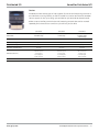


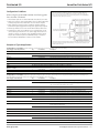
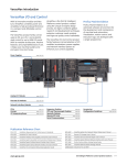
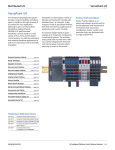

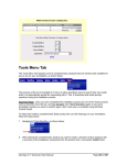

![Olympus µ[mju:]-mini DIGITAL](http://vs1.manualzilla.com/store/data/007181998_1-9144a7fcfac5b4a8090058e0c5c18757-150x150.png)