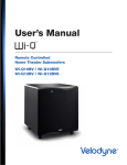
1
SET UP
U S E R ’ S
M A N U A L
WiConnect
System
Enjoy.
We here at Velodyne want to thank you for selecting our product.
Get ready to experience the highest quality and amazing low-distortion
bass that Velodyne is world famous for. Relax as you enhance your
home entertainment experience with our easy setup instructions.
Welcome . . . enjoy your new Velodyne!
1
Safety Notice
SET UP
3
Box Contents
5
Connect Wireless Transmitter to Audio Receiver
7
Select Audio Receiver Options Optimal Subwoofer Performance
8
Connect Subwoofer
8
Select Wireless Broadcast Channel
8
9
— Wireless Broadcast Considerations
Connect Multiple Wireless Subwoofers
9
— In a Single Audio System
9
— In Separate Audio Systems
10
Mount Wireless Transmitter on Wall (Optional)
M A I N TA I N
11
Protect Transmitter and Receiver from Damage
11
Clean
11
Service
12
Troubleshoot
12
Packaging
RESOURCES
13
Specifications
14
Regulatory Information
14
— FCC Compliance Statement
14
— FCC Warning
14
— European Union (EU) Declaration of Conformity
14
Radio Frequency Exposure Limit Requirements
14
Listen Responsibly
14
Legal Notice
14
— Electronics Recycling
14
— Trademarks
15
Warranty
SAFETY NOTICE
W iConnect System User’s Manual
SAFETY NOTICE
CAUTION: To reduce the risk of electric shock, do not remove cover (or back). No user-serviceable parts inside. Refer servicing to qualified
service personnel.
ThE lIghTNINg flASh wITh ARROwhEAd SyMbOl is intended to alert the user to the presence of uninsulated “dangerous voltage”
within the product’s enclosure that may be of sufficient magnitude to constitute a risk of electric shock to persons.
ThE ExClAMATION POINT SyMbOl is intended to alert the user to the presence of important operating and maintenance (servicing)
instructions in the literature accompanying the subwoofer.
1. READ INSTRUCTIONS — All safety and operating instructions should be read before the product is operated.
2. RETAIN INSTRUCTIONS — The safety and operating instructions should be retained for future reference.
3. HEED WARNINGS — All warnings on the product and in the operating instructions should be adhered to.
4. FOLLOW INSTRUCTIONS — All operating and use instructions should be followed.
5. WATER AND MOISTURE — The product should not be used near water — for example, near a bathtub, washbowl, kitchen sink, laundry
tub, in a wet basement, near a swimming pool or the like.
6. CARTS AND STANDS — The product should be used only with a cart or stand recommended by the manufacturer.
7. WALL OR CEILING MOUNTING — The product should be mounted to a wall or ceiling only as recommended by the manufacturer.
8. VENTILATION — The product should be situated so that its location or position does not interfere with its proper ventilation. For example,
the product should not be situated on a bed, sofa, rug, or similar surface that may block the ventilation openings; or placed in a built-in
installation such as a bookcase or cabinet that may impede the flow of air through the ventilation openings.
9. HEAT — The product should be situated away from heat sources such as radiators, heat registers, stoves, or other products that
produce heat.
10. POWER SOURCES — The product should be connected to a power supply only of the type described in the operating instructions or as
marked on the product.
11. GROUNDING OR POLARIzATION — This product may be equipped with a polarized alternating-current line plug (a plug having one
blade wider than the other). This plug will fit into the power outlet only one way. This is a safety feature. If you are unable to insert the plug
fully into the outlet, try reversing the plug.If the plug should still fail to fit, contact your electrician to replace your obsolete outlet. Do not
defeat the safety purpose of the polarized plug.
[1]
SAFETY NOTICE
W iConnect System User’s Manual
12. POWER-CORD PROTECTION — Power-supply cords should be routed so that they are not likely to be walked on or pinched by items
placed upon or against them, paying particular attention to cords at plugs, convenience receptacles, and the point at which they exit from
the product.
13. CLEANING — The product should be cleaned only as recommended by the manufacturer.
14. NONUSE PERIODS — The power cord of the product should be unplugged from the outlet when left unused for a long period of time.
15. OBjECT AND LIqUID ENTRy — Care should be taken so that objects do not fall and liquids are not spilled onto the enclosure.
16. DAMAGE REqUIRING SERVICE — The product should be serviced by qualified service personnel when:
a. The power-supply cord or plug has been damaged.
b. Objects have fallen or liquid has been spilled into the product.
c. The product has been exposed to rain.
d. The product does not appear to operate normally or exhibits a marked change in performance.
e. The product has been dropped or damaged.
17. SERVICING — The user should not attempt to service the product beyond what is described in the operating instructions. All other
servicing should be referred to qualified service personnel.
18. LIGHTNING — For added protection for the product during a lightning storm or when it is left unattended and unused for long periods of
time, unplug it from the wall outlet.
19. OVERLOADING — Do not overload wall outlets, extension cords or integral convenience receptacles as this can result in a risk of fire or
electric shock.
20. ATTACHMENTS — Only use attachments and accessories specified by the manufacturer.
21. VOLTAGE — Insure that the product is only connected to the rated source voltage. Do not connect the 120-volt version to 230-volts or
vice-versa. This will result in damage to the product and possible injury to the user.
CAUTION: To prevent electrical shock, match wide blade of plug to wide slot, fully inserted.
[2]
SET UP
W iConnect System User’s Manual
Box Contents
Now that you’ve unpacked the WiConnect System, make sure you have the components and Velodyne supplied accessories shown below.
If any components or Velodyne supplied accessories are missing or damaged, contact the retailer where you purchased this product.
A
b
Components
Velodyne Supplied Accessories
A. Wireless transmitter
• (2) 5V DC power adapters for
b. Wireless receiver
wireless transmitter.
• Self-tapping wood screws (2) for
• (2) 1 meter RCA cables. One for
connecting wireless transmitter to
receiver, and the second for connecting
wireless receiver to subwoofer.
wireless transmitter mounting.
wireless Transmitter
A. INPUTS
• L and R: Inputs for connecting to your
receiver’s RCA output.
• LFE: Output for connecting to your
receiver’s LFE output.
b. ChANNEl SElECTOR: Switch for
C. 5V dC Power adapter socket
choosing the broadcast frequency by
CHANNEL. This CHANNEL selector
switch of the WiConnect System
receiver should be set to the same
CHANNEL as the transmitter.
[3]
d. blUE lEd: Indicates transmitter
is active.
SET UP
W iConnect System User’s Manual
wireless Receiver
A. OUTPUTS
• L and R: Outputs for connecting to
your subwoofer’s RCA input.
• LFE: Output for connecting to your
subwoofer’s LFE input.
b. ChANNEl SElECTOR: Switch for
C. 5V dC Power adapter socket
choosing the broadcast frequency by
CHANNEL. This CHANNEL selector
switch of the WiConnect System
receiver should be set to the same
CHANNEL as the transmitter.
[4]
d. gREEN lEd: Indicates receiver
is active.
SET UP
W iConnect System User’s Manual
Connect Wireless Transmitter to Audio Receiver
Use one of the following two setups to connect the wireless transmitter to receiver:
SETUP #1:
SETUP #2:
MOST COMMON
LESS COMMON
(RECEIVER LFE/SUB OUTPUT)
(NO RECEIVER LFE/SUB OUTPUT)
This setup requires one RCA cable.
This setup requires one RCA cable for
each of the L and R channels.
1
2
SETUP #1: MOST COMMON (RECEIVER HAS LFE/SUB OUTPUT)
1. Use one of the RCA cables supplied
2. Plug the wireless transmitter’s 5V DC
The WiConnect System receiver
to connect the wireless transmitter’s
power adapter into the back of the
must be within 50 feet (15
LFE input to your receiver’s LFE or
wireless transmitter. Plug the other
meters) from its transmitter to be able to
SUB output. Connect with one
end of the adapter into a power outlet.
receive the wireless signal. Also, make
lead only.
sure that the same CHANNEL is selected
3. go to the Select Receiver Options
for Optimal Subwoofer Performance
instructions next.
[5]
on both the transmitter and receiver.
SET UP
W iConnect System User’s Manual
1
2
SETUP #2: LESS COMMON (RECEIVER HAS NO LFE/SUB OUTPUT)
1. Use one of the RCA cables supplied
to connect the wireless transmitter’s
wireless transmitter. Plug the other
The WiConnect receiver must be
end of the adapter into a power outlet.
within 50 feet (15 meters) from
R and L inputs to your receiver’s
R and L outputs.
2. Plug the wireless transmitter’s 5V DC
its transmitter to be able to receive the
3. go to the Select Receiver Options
wireless signal. Also, make sure that
for Optimal Subwoofer Performance
the same CHANNEL is selected on
instructions next.
both the transmitter and receiver.
power adapter into the back of the
[6]
SET UP
W iConnect System User’s Manual
Select Audio Receiver Options For Optimal Subwoofer Performance
It is important that the audio receiver is set up correctly to work in concert with the WiConnect System. To set up the audio receiver refer to its
instruction manual and use one of the following three options:
AUDIO RECEIvER OPTIONS
OPTION #1
OPTION# 2
OPTION #3
(MOST COMMON)
(LESS COMMON)
(LESS COMMON)
SETUP #1:
SETUP #1:
SETUP #2:
(MOST COMMON)
(MOST COMMON)
(LESS COMMON)
yes
yes
No
yes
No
No
No
yes
yes
This setup uses the audio
receiver’s lowpass crossover filter
instead of your subwoofer’s filter.
This setup uses your subwoofer’s
lowpass crossover filter instead
of the audio receiver’s filter.
This setup uses your subwoofer’s
lowpass crossover filter instead
of the audio receiver’s filter.
wireless Transmitter SETUP
Audio Receiver has lfE or
SUb output
Use receiver’s lfE or SUb
output as subwoofer’s input
Use audio receiver’s unfiltered/full
frequency range R and l outputs
as subwoofer’s inputs
AUdIO RECEIVER OPTION #1
The audio receiver’s LFE or SUB output is the input to the subwoofer (most common case). Use the audio receiver’s speaker menu and set
as follows:
1. Select that you have a subwoofer.
2. Select the number of speakers.
3. Select the speaker size as SMALL.
4. If you don’t know the low frequency limit of your main speakers, use 80 Hz as the crossover point. The lower limit of the main
speaker’s frequency response is usually listed in the speaker specifications as, for example, “3 dB down at 45 Hz.”
In this example, double the value (45 Hz) and use the doubled-value (90 Hz) as the crossover frequency.
5. Adjust the LFE /SUB output level to 0 dB.
6. Go to the Connect Subwoofer instructions next.
AUdIO RECEIVER OPTION #2
The audio receiver’s unfiltered/full frequency range R and L output channels, not its LFE or SUB output, is the input to the WiConnect System
(less common case). Use the audio receiver’s speaker menu and set as follows:
1. Select that you have NO subwoofer.
2. Select the number of speakers.
3. Select the speaker size as LARGE.
4. If the crossover frequency option is available, double your main speakers specified low frequency response value and select
the result as the crossover frequency. If you don’t know the low frequency response value, use 80 Hz.
5. Go to the Connect Subwoofer instructions next.
AUdIO RECEIVER OPTION #3
The audio receiver has no LFE or SUB output:
1. No selections to make in the receiver’s speaker menu.
2. Go to the Connect Subwoofer instructions next.
[7]
SET UP
W iConnect System User’s Manual
Connect Subwoofer
1. Place WiConnect System RF receiver near your subwoofer. Do not place in a metal cabinet — this may degrade reception performance.
2. Attach included 5V DC power adapter to WiConnect System receiver.
3. Attach the appropriate RCA cables, depending on the audio receiver option chosen between the WiConnect System receiver and
your subwoofer.
4. Plug RF receiver or WiConnect System power adapter into wall outlet.
5. Turn the VOLUME knob to MIN to prevent blasting music when you first use the subwoofer. you can increase the VOLUME to the
correct level later.
6. Turn on subwoofer.
7. you’re done. No more wires to connect!
7. Go to the Select wireless broadcast Channel instructions next.
Select Wireless Broadcast Channel
The wireless transmitter can broadcast your audio signals on one of four selectable channels. Multiple channels are made available in case
other devices in your home are using some of the channels for communication, or if you plan to use more than one WiConnect System
(only up to four total WiConnect Systems can be used within 50 feet of each other).
To select the broadcast channel:
1. Review the wireless broadcast Considerations below.
2. Use the CHANNEL switch on the back of the wireless transmitter to select “1”, “2”, “3”, or “4” as the broadcast channel.
3. Use the CHANNEL switch on the back of the wireless receiver to select the same broadcast channel as you selected on the
wireless transmitter.
Wireless Broadcast Considerations
All wireless devices like the WiConnect System may be susceptible to radio frequency (RF) interference from other devices, depending on
frequency used. Other RF devices include WiFi Internet access, computer equipment and routers; WiFi solar panel monitoring systems;
video game consoles, cordless telephones, blue tooth devices, baby monitors and microwave ovens. In particular, any devices operating in
the 2.4 GHz band may cause intermittent wireless connections between the wireless transmitter and wireless receiver.
To prevent wireless broadcast interference problems, keep wireless transmitters at least 2’ apart. Any interference effects from a microwave
oven will cease once the oven stops operating and may be resolved on a long-term basis by increasing the physical distance between the
WiConnect System and the microwave oven.
If the WiConnect System sound is intermittent, check that another wireless device isn’t within 2’ of either the wireless transmitter or the wireless
receiver. Also, try one of the other broadcast channels of the WiConnect System as it may be free of the RF interference.
[8]
SET UP
W iConnect System User’s Manual
Connect Multiple Wireless Subwoofers
In a Single Audio System
If you are using more than one WiConnect System in a single audio system, or in two audio systems close together, the following two setup
options exist.
OPTION #1: All subwoofers receive the same audio signal. This is the most common setup. For this setup:
1. Connect only one wireless transmitter to your audio receiver. Follow the instructions for OPTION #1 or OPTION #2 in the
Connect wireless Transmitter Section.
2. Follow the instructions for SETUP #1 in the Select Audio Receiver Options for Optimal Subwoofer Performance section.
3. Set the same wireless broadcast channel on the wireless transmitter and all RF receivers. Follow the instructions in the
Select wireless broadcast Channel section.
OPTION #2: Subwoofers receive different audio signals. This is a less common setup. Usually, this setup uses one subwoofer for the R audio
channel and one subwoofer for the L audio channel, or for two differently purposed audio systems on either side of a wall. If using separate
R and L channel subwoofers, place each subwoofer within a couple of feet of the appropriate main speaker for the channel. If the system’s
crossover frequency is high, each subwoofer should be even closer to its channel’s main speaker. For this setup:
1. Connect a wireless transmitter to each signal you want to transmit to a receiver. Usually, one for the R and one for the L channel.
Follow instructions for SETUP #2 in the Connect wireless Transmitter Section, except pair one transmitter’s R input to the R
channel receiver output and the other transmitter’s L channel input to the L channel receiver output.
2. Follow the instructions for OPTION #3 in the Select Audio Receiver Options for Optimal Subwoofer Performance section.
3. Follow the instructions in the Select wireless broadcast Channel section, except:
a. Select a unique wireless broadcast channel for each wireless transmitter.
b. Match the wireless broadcast channel on each WiConnect receiver to that of the WiConnect transmitter that broadcasts the audio
signal that WiConnect receiver is to output.
4. Follow the instructions in the Adjust Subwoofer Controls section for each subwoofer.
In Separate Audio Systems
If you have multiple audio systems in your home, such as one in the family movie room and another in a bedroom or office, you can use a
separate wireless transmitter in each system. In this case, use a different wireless broadcast channel for each system, to avoid the
subwoofers from getting input from multiple systems due to the close proximity of the systems.
[9]
SET UP
W iConnect System User’s Manual
Mount Wireless Transmitter or Receiver on Wall (Optional)
Optionally, you can mount the wireless transmitter or receiver on the wall or place in a location that better organizes your audio components.
The WiConnect System doesn’t have to be visually in view in the room to function properly
1. Use the template below to mark the mounting locations on the
3. Hook two of the slotted holes on back of the wireless
wall. Mark the two screw locations for either the horizontal or
transmitter to the two screws. There is no right way up for
vertical mounting orientation.
the transmitter. It can be mounted in any orientation.
2. Hand turn one of the included self-tapping wood screws into
The provided wood screws aren’t suitable for stone
each marked location. Tighten the screws until about 1/8”
or other hard wall surfaces. If you can’t hand drive
(3.17mm) of the screw shank is exposed.
the screws, you may need to drill holes and provide other
wall anchors.
wireless Transmitter Mounting Template
[ 10 ]
MAINTAIN
W iConnect System User’s Manual
MAINTAIN
Protect Transmitter and Receiver from Damage
DO NOT PUT OBjECTS ON TOP of the transmitter or receiver case that could scratch or otherwise damage the case.
DO NOT ALLOW OBjECTS TO FALL ON OR LIqUIDS TO SPILL ON THE TRANSMITTER OR RECEIVER CASE.
DO NOT EXPOSE TRANSMITTER OR RECEIVER TO DRIPPING OR SPLASHING FROM LIqUIDS.
DO NOT PLACE LIqUID-FILLED OBjECTS ON OR NEAR THE TRANSMITTER OR RECEIVER. Examples of liquid-filled objects include
flower vases, beverages and liquid-fueled lamps.
DO NOT PUSH OBjECTS OF ANy KIND into the transmitter or receiver openings.
DO NOT PLACE BURNING CANDLES, INCENSE, OR SMOKING PRODUCTS ON TOP OF OR NEAR THE TRANSMITTER OR RECEIVER.
Clean
USE A CLEAN, SOFT DAMP CLOTH to remove dust or fingerprints from the transmitter or receiver case. Unplug the power cord from the
power outlet before cleaning to prevent static electricity from damaging the transmitter or receiver during cleaning.
DO NOT CLEAN THE WIRELESS TRANSMITTER OR RECEIVER CASE with detergents, soaps, abrasives, aerosol sprays, chemical
solvents, alcohol, or other cleaning solutions.
Service
DO NOT ATTEMPT TO SERVICE THE WIRELESS TRANSMITTER OR RECEIVER yOURSELF beyond what is described in this
owner’s manual.
ONLy USE qUALIFIED SERVICE TECHNICIANS TO REPAIR DAMAGED PARTS. Service the transmitter or receiver using qualified service
technicians when:
• A power cord or plug is damaged
• The power socket on the transmitter or receiver is damaged
• Objects have fallen on, or liquid has spilled into the transmitter or receiver
• The transmitter or receiver was rained on or has become partially or fully submerged in water
• The transmitter or receiver does not operate normally or exhibits a marked change in performance
• The transmitter and receiver has been dropped or is damaged
[ 11 ]
MAINTAIN
W iConnect System User’s Manual
Troubleshoot
THE TRANSMITTER OR RECEIVER LED IS NOT LIT:
1. Verify that the power adapter is plugged into a live power outlet.
2. Verify that the power adapter is not damaged.
IF yOUR SUBWOOFER ISN’T PRODUCING SOUND, BUT THE TRANSMITTER ACTIVE LIGHT IS BLUE AND THE RECEIVER LIGHT IS
SOLID GREEN:
1. Verify that the wireless transmitter is plugged into a live power outlet. The receiver’s green LED will blink if it does not receive the
transmitter’s signal.
2. Verify that the wireless transmitter’s inputs are connected to the audio receiver’s output. This wire may have become
accidentally disconnected.
3. Increase the subwoofer’s VOLUME level.
4. Increase the receiver’s LFE or SUB OUT volume level, if it is adjustable.
5. If your receiver has a switch or menu to enable its LFE or SUB OUT, make sure this switch or menu is set to ON or yES.
6. Verify that the wireless transmitter’s light is on solid. If the transmitter’s light isn’t on solid and the same CHANNEL is selected
on both the wireless transmitter and receiver, select another matching CHANNEL for the wireless transmitter and receiver.
IF THE BASS DOESN’T SOUND LOUD ENOUGH TO yOU:
1. Increase the subwoofer’s VOLUME level.
2. Increase the receiver’s LFE or SUB OUT volume level, if it is adjustable.
3. Put the subwoofer closer to a corner of your room.
OR
The transmitter and receiver may have lost their broadcast connection.
1. Turn off power to the subwoofer, wireless transmitter, and wireless receiver.
2. Turn back on power to the wireless transmitter, then the wireless receiver, and then the subwoofer.
3. If cycling the power doesn’t re-establish the broadcast connection, select another matching CHANNEL for the wireless
transmitter and receiver.
4. If selecting another CHANNEL doesn’t re-establish the broadcast connection, decrease the distance between the wireless receiver
and the wireless transmitter to increase the broadcast signal strength between them.
5. Verify that the transmitter and wireless receiver aren’t in close proximity to other electronic devices that could interfere with the
wireless transmission and reception.
Packaging
Save the carton and packing materials for future use. Using other packaging for this unit may result in severe damage when shipping or
moving. you can use this packaging should you ever move or need to return the WiConnect System to Velodyne for service. To save
storage space, you can flatten the box and put the other packing material in a plastic bag.
[ 12 ]
RESOURCES
W iConnect System User’s Manual
RESOURCES
Specifications
Model
wiConnect System
Frequency Response
20 Hz – 16k Hz (+/- 0.5 dB)
Speaker-level Pass-through
Full range
Input Impedence
10k ohm
LED Power Indicator
yes
Case (H x W x D)
1.0312” x 5.125” x 3.25” (29.4 mm x 130.2 mm x 82.6 mm)
Shipping Weight (approximate)
5 lbs. (2 Kg)
Wireless Transmitter Range
50’ (15 m)
Wireless Transmitter Frequency
2.4 GHz
A Note on bandwidth:
Although this manual is written from the perspective of wireless signal transmission for subwoofers, you will see when reviewing the
specifications that the WiConnect System has a very wide bandwidth (20-16k Hz +/- 0.5 dB). Thus, it could be used in some cases for
full range signals as well.
[ 13 ]
RESOURCES
W iConnect System User’s Manual
Regulatory Information
fCC Compliance Statement
This device complies with part 15 of the FCC Rules. Operation is subject to the following two conditions:
1. This device may not cause harmful interference, and
2. This device must accept any interference received, including interference that may cause undesired operation.
fCC warning
This equipment has been tested and found to comply with the limits for a Class B digital device, pursuant to Part 15 of the FCC Rules. These
limits are designed to provide reasonable protection against harmful interference in a residential installation. This equipment generates, uses
and can radiate radio frequency energy and, if not installed and used in accordance with the instructions, may cause harmful interference to
radio communications. However, there is no guarantee that interference will not occur in a particular installation. If this equipment does cause
harmful interference to radio or television reception, which can be determined by turning the equipment off and on, the user is encouraged to
try to correct the interference by one or more of the following measures:
• Reorient or relocate the receiving antenna.
• Increase the separation between the equipment and the receiver.
• Connect the equipment into an outlet different from that to which the receiver is connected.
• Consult the dealer or an experienced radio/TV technician for help.
The Federal Communications Commission warns that changes or modifications of the unit not expressly approved by the party responsible for
compliance could void the user’s authority to operate the equipment.
E u r o p E a n u n i o n ( E u ) D E c l a r at i o n o f c o n f o r m i t y
This product complies with the requirements and other relevant provisions of the R&TTE Directive as well as CE-LVD (Safety) and CE-EMC
(Emissions & Immunity).
Radio frequency Exposure limit Requirements
Keep a minimum separation of 8 inches (20 cm) between the transmitter and any person to comply with FCC and EU exposure
limit requirements.
listen Responsibly
REFRAIN FROM LISTENING TO MUSIC AT HIGH VOLUMES for long periods of time to protect you from permanent hearing damage. The
United States Occupational Health and Safety Administration (OSHA) standards recommend not listening to sound levels of 85 dB for more
than 8 hours and to wear hearing protection if sound levels exceed 85 dB. Refer to the OSHA website for more information and updated
recommendations about sound levels and hearing damage: www.osha.gov/dts/osta/otm/noise/standards_more.html
Legal Notice
Electronics Recycling
These products should not be treated as household waste. Instead, the transmitter, receiver, and power supplies should be taken to a certified
collection point so that the electrical and electronic components can be recycled. By recycling these products through a certified collection
point, you prevent potential environmental damage and help to conserve natural resources used in these products. Certain international,
national and/or local laws and/or regulations may also apply regarding the disposal of this subwoofer. For further information, contact your
local waste disposal service, your local city government office, or the retailer where you purchased this subwoofer.
Trademarks
The Velodyne logo is a trademark of Velodyne Acoustics, Inc.
[ 14 ]
WARRANTY
W iConnect System User’s Manual
FOR YOUR RECORDS. . .
Date Purchased _____________________________________________________________________________________
Dealer ______________________________________________________________________________________________
Serial # ____________________________________________________________________________________________
*NOTE: Please complete and return your warranty card within ten (10) days or
Register. . . ON LINE . . . It’s faster . . . and easier www.velodyne.com
[ 15 ]
Velodyne Acoustics, Inc.
345 Digital Drive
Morgan Hill, CA 95037
408.465.2800 voice
408.779.9227 fax
408.779.9208 service fax
www.velodyne.com
Service E-mail: [email protected]
General E-mail: [email protected]
63-170 WiConnect System Manual Rev B JUN13