1
GARMIN Ltd. or its Subsidiaries, c/o
Garmin International 1200 E. 151st Street
Olathe, KS 66062 USA
AIRPLANE FLIGHT MANUAL SUPPLEMENT or
SUPPLEMENTAL AIRPLANE FLIGHT MANUAL
for STC SA02015SE-D GARMIN G500 SYSTEM
Section 1. GENERAL
1.1 Garmin G500 Primary Flight / Multi-Function Display System
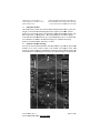
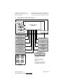
The G500 PFD/MFD System consists of a Primary Flight Display (PFD) and
Multi-Function Display (MFD) housed in a single Garmin Display Unit (GDU),
plus an Air Data Computer (ADC) and Attitude and Heading Reference System
(AHRS). The G500 interfaces with other installed systems in the aircraft,
including Garmin GNS series GPS/WAAS navigators, Garmin SL30 VHF
navigators, Garmin GDL 69 data link radios, and various audio panels, traffic
systems and ADF navigators.
The primary function of the PFD is to provide attitude, heading, air data and
navigation information (from GNS units) to the pilot. The primary function of the
MFD is to provide mapping, terrain, and flight plan information.
The standby instruments (altimeter, airspeed, attitude, and magnetic compass) are
completely independent from the PFD and will continue to operate in the event
the PFD is not usable. These standby instruments should be included in the pilot’s
normal instrument scan and may be referenced if the PFD data is in question. A
second G500 system installed on the co-pilot’s side does not require additional
standby instruments.
1.2 System Power Sources
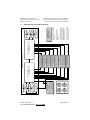
The G500 system depends on electrical power to maintain proper operation. The
Garmin Display Unit (GDU), Attitude and Heading Reference System (AHRS),
and Air Data Computer (ADC) should be directly tied to the aircraft’s main or
essential bus and energized when the aircraft master switch is turned on. Other
systems, like the navigation equipment, weather datalink, autopilot and Adapter
(GAD) are typically located on the avionics bus and may not be operable during
engine start.
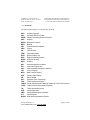
The major components of the G500 are circuit breaker protected with reset-able
type breaker available to the pilot. These breakers are located at the main or
essential bus circuit breaker panel and labeled as follows:
1.
2.
3.
4.
PFD
AHRS
ADC
GAD
-
Garmin Display Unit (PFD/MFD), GDU 620
Attitude and Heading Reference System, GRS 77
Air Data Computer, GDC 74A
Garmin Adapter, GAD 43 (optional)
Note: In dual installations the pilot side equipment is suffixed with a “1” and the
copilot side equipment is suffixed with a “2”; Example: PFD 2.
190-01102-01 Rev. 4
FAA APPROVED DATE: AUG 24, 2010
Page 5 of 29