1
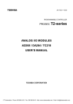
NCP1203GEVB
A 70 W Low Standby
Power Supply with
the NCP120x Series
Evaluation Board User's
Manual
http://onsemi.com
EVAL BOARD USER’S MANUAL
Introduction
this level. Thanks to the natural secondary / auxiliary
reflection, the primary auxiliary winding cannot
maintain a sufficient voltage on the control IC: Vcc
collapses and puts the controller in trouble, probably
entering an hiccup mode, similar to that of a startup
sequence. DSS being decoupled from Vout, you never
see that phenomenon.
As you can see, the DSS offers interesting features but, on
the other hand, it can sometimes compromise key design
parameters. Standby power and power dissipation are one of
these:
• Standby power: the DSS standby power contribution
can easily be evaluated: VHV × Iavg with Iavg, the current
consumption taken by the controller and VHV, the
high−voltage supply rail. If Iavg equals 1 mA, then we
have a standby power of 350 mW at a 350 VDC voltage
rail. Tricks exist to slightly reduce it, like the half−wave
diode, but you will only gain between 20–30%.
• Power dissipation: as stated above, all the current
consumed by the IC is seen through pin8. This is due to
the self−adaptive feature of the DSS. Should the IC
current move up or down, the DSS duty−cycle will
automatically adjust to deliver it. The controller current
depends on the internal IC consumption, but also on the
type of MOSFET connected to the output. It therefore
important to assess the total current drawn from the HV
rail and checks the right compatibility with the package
type. All details are given in the NCP1200 dedicated
data sheet and the application note AND8023/D.
As a result, the answer lies behind your design constraints.
If you would like to have a precise Over Current Protection
(OCP) trip point while driving a moderate size MOSFET,
DSS can be a good choice, provided low standby power is
not an absolute necessity. In our case, we want to drive a
large MOSFET for a better efficiency but we need to reach
the lowest possible standby power. We will thus adopt an
auxiliary winding configuration to permanently disable the
DSS. Solutions to various combinations of these constraints
are described in the application note “Tips and Tricks for the
NCP1200,” document number AND8069/D.
The NCP1200 represents one of the cheapest solutions to
build efficient and cost−effective Switch−Mode Power
Supplies (SMPS). As this design example will show, the part
definition does not confine the component in low−power
applications only, but it can actually be used in Flyback and
Forward supplies for virtually any output power. The below
example depicts a universal mains 90−260 VAC power
supply delivering 16.5 V @ 4.5 A.
Beside its ease of implementation, the NCP1200 excels in
true low standby power designs. This application note
details how an amazing standby power of less than 100 mW
can be reached at high line with a nominal 70 W board.
DSS or Not DSS?
The Dynamic Self Supply (DSS) lets you directly drive
MOSFETs from the high−voltage rail. This option brings
you several advantages, as stated below:
• True overload detection: with UC384X−based systems,
the switching oscillations are stopped in case the Vcc
line drops below a given Undervoltage Lockout level
(UVLO). This principle considers a good coupling
between the primary auxiliary winding and the power
secondary winding. Unfortunately, leakage elements
often degrade this coupling and you only can detect true
short−circuit (when Vout is close to zero) and not
overload conditions. Thanks to the DSS, the NCP1200
does not need an auxiliary information to sense an
overload condition. By detecting a current setpoint
pushed to the maximum, the internal logic takes the
decision to enter into a safe burst operation,
auto−recovering when the default leaves. Precise
overload levels can thus be implemented.
• Guaranteed operation at low output levels: the Vcc
delivered by an auxiliary winding moves with the
power output level because a coupling exists between
both windings. When the supply is used in battery
charging applications, Vout can move depending on the
charging state. That is to say, when the battery is nearly
empty, its voltage can be close to zero, forcing Vout at
www.BDTIC.com/ON/
© Semiconductor Components Industries, LLC, 2012
June, 2012 − Rev. 3
1
Publication Order Number:
EVBUM2124/D
NCP1203GEVB
Figure 1. Evaluation Board Picture
Self−Powering the Controller in Standby
1
An auxiliary winding does not usually cause any
self−supply problem with a continuous pulses flow. In
standby, whatever implemented frequency reduction
techniques (e.g. skip or frequency foldback), the recurrence
between pulses can become very low. By definition, the
feedback loop manages to keep the energy content in each
burst high enough to maintain the nominal output voltage.
However, on the auxiliary side, it can be difficult to keep the
Vcc above the controller’s UVLO. Remember, to
permanently disable the DSS, you need to guarantee a level
above VccON max. which is 11 V for the NCP1200. Failure
to do this will re−activate the DSS in no−load conditions and
standby power will be degraded. Figure 2 offers a view of a
typical bunch of pulses captured in standby at a 127 VDC
input voltage.
2
8
NCP1200
7
3
6
4
5
Rlimit
3
CVcc
1N4148
2
15 V
Caux
1
Laux
Figure 3. The Auxiliary Is Clamped to Avoid
Exceeding the 16 V Maximum Rating
As we previously stated, we want to deliver 70 W with a
16.5 V output level. The maximum rating for the NCP1200
states a level less than 16 V. As a result, the auxiliary Vcc
shall be less than 16V but also above VccON in any
conditions to ensure full DSS de−activation. A solution
consists in artificially raising the ratio between the power
winding and the auxiliary one to ensure adequate supply at
no−load. We successfully tested a 0.9 ratio, where the
auxiliary output gets clamped by a 15V Zener diode in
nominal operation. Figure 3 shows the option.
We measured a Vcc of 11.5 V @ 230 VAC and 12.2 V @
90 VAC. Rlimit on Figure 3 can easily be adjusted to move
these values up or down, depending on the final winding
ratios. Care must be taken to avoid over−dissipation of the
15 V Zener diode in nominal conditions.
33 ms
Power Supply, Element−by−Element Design
200 μs
Let’s first detail the specs of our power supply:
Vin: 90–265 VAC
Vout: 16.8 V @ 4.2 A (Pout = 70 W)
Short−circuit protection
Over−voltage protection
Efficiency > 80%
Pin = 70 / 0.8 = 87.5
The below sequence details step−by−step the calculation
procedure for every component of the power supply.
Figure 2. A Bunch of Auxiliary Pulses Captured
While the Supply Operates at No−Load
(Vin = 127 VDC)
www.BDTIC.com/ON/
http://onsemi.com
2
NCP1203GEVB
DC High−Voltage Rail
Diode Bridge Selection
From these above numbers, we can deduce the level of the
high−voltage rail, neglecting the dual Vf drop:
To select the right rectifiers, it is necessary to know the
RMS current flowing through its internal diodes. Prior to
reach this final result, we need to evaluate the diode
conduction time. From Figure 5, we can see that the diode
starts to conduct when VACin reaches Vmin and stops when
reaching Vinpeak:
VHV max + 265 @ Ǹ2 + 374 VDC
VHV min + 90 @ Ǹ2 + 127 VDC
Vripple
tc
Vinpeak
Vmin
Vinpeak
Vbulk
VHVavg
10 ms
300 mA
Idiode
VAC in
X−2 ms/div
Figure 4. A Typical Ripple Voltage Over the Bulk
Capacitor
Figure 5. When VACin Reaches Vpeak, the Diode
Stops Conducting
From a mathematical point of view, we can calculate the
time VACin takes to reach Vmin, with Vmin = Vpeak −
Vripple:
Bulk Capacitor
Figure 4 portrays the typical waveform captured across a
bulk capacitor delivering power to a given charge. To
simplify the calculation, we will neglect the charging period
and thus consider a total discharge time equal to 1/(2 ⋅ Fline).
From the design characteristics, we can evaluate the
equivalent current (Iload) drawn by the charge at the lowest
input line condition. Let’s us adopt a 40% ripple level, or a
50 V drop from the corresponding Vinpeak. To evaluate the
equivalent load current (which discharges Cbulk between
the peaks), we divide the input power by the average
rectified voltage:
Iload +
VACin @ sin(w @ t) + Vmin
Since Vpeak is reached at the input sinusoid top (or one
fourth of the input period), then the diode conducting time
tc is simply:
tc +
[ 860 mA DC @ 90 VAC input voltage
Ǔ
(3)
360 @ Fline
Qbulk + Vripple @ Cbulk + 9 mC
Thanks to Figure 4 information, we can evaluate the
capacitor value which allows the drop from Vpeak down to
Vavg − (Vripple/2) to stay within our 50 V target, dV ⋅ C =
iload ⋅ dt:
Vripple
2
(4)
From Figure 5, we can calculate the amount of charge Q
drawn from the input by integrating the input current over
the diode conduction time:
(2)
Pout
2 @ h @ Fline @ Vripple @ ǒVpeak *
Vmin
VACin@Ǹ2
During these 3 ms, Vbulk is the seat of a rising voltage equal
to Vripple or 50 Vpp. This corresponds to a brought charge
Q of:
2
Cbulk +
ǒ
sin −1
[ 3 ms @ Vin + 90 VAC
(1)
Pout
Pin
+
Vripple
Vrectavg
ǒ
Ǔ
h @ Vpeak *
1
*
4 @ Fline
tc
Ǔ
Qin +
ŕ idiode(t).dt
0
w 171 mF or 180 mF for a normalized value
The expression of idiode(t) is:
(Fline = 50 Hz worse case).
www.BDTIC.com/ON/
http://onsemi.com
3
(5)
NCP1203GEVB
Ipeak @ tc * t
tc
Turn Ratio and Output Diode Selection
(6)
The primary/secondary turn ratio affects several
parameters:
• The drain plateau voltage during the OFF time: the
lowest plateau gives room for the leakage inductance
spike before reaching the MOSFET’s BVdss:
After proper integration, it comes:
Qin + 1 @ Ipeak @ tc
2
If we now equate Qbulk and Qin and solve for Ipeak, it comes:
Qbulk @ 2
Ipeak +
tc
Vplateau +
(7)
Irms +
Ǹ
Fline @
+ Ipeak @
Ǹ
ŕ (idiode(t))2 @ dt
the turn ratio and the regulated output voltage by:
PIV + Ns @ VinDC max ) Vout
Np
(8)
(11)
If you lower the plateau voltage, you will increase the
reverse voltage the secondary diode must sustain.
With these numbers in mind, you can tweak the turn ratio
according to the MOSFET BVdss and the diode maximum
reverse voltage. A Schottky diode represents a good choice,
especially with a power supply that can possibly enter
Continuous Conduction Mode (CCM). The lack of reverse
recovery loss and a low forward drop play in favor of this
component. However, because of the metal−silicon
junction, moderate breakdown voltages are available for a
moderate cost. The MBR20100 represents an interesting
choice since it welcomes two 100 V Schottky in a TO−220
package. Being in thermal contact, a parallel wiring is
possible. The 100 V VRRM lets us calculate the minimum
turn ratio we can go down to, keeping an acceptable safety
margin:
0
tc @ 2 @ Fline
3
+ 1.9 A @ VAC + 90
We selected a KBU4J diode bridge (600 V/4 A) for the
rectifying function. A small resistor, or best an NTC, can
however be put in series to limit the surge current (when you
plug the SMPS in the AC outlet) to less than the diode
maximum peak current (Ifsm) or what the standard imposes
you.
Thanks to these numbers, we compute the apparent power
at low line: 1.9 A × 90 V = 170 VA which compared to our
87.5 Watts of active power (neglecting the input diode
bridge and Cbulk losses) gives a power factor of:
PF + W + 0.51
V.A
(10)
• The secondary Peak Inverse Voltage (PIV) is linked to
or 6 A peak. We can now evaluate the RMS current flowing
through the diodes:
tc
Np
@ (Vout ) Vf) ) VinDC max
Ns
N + PIV * Vout
VinDC max
(9)
(12)
→ Np:Ns ≤ 1:0.221. A final ratio of 1:0.166 offers an
adequate safety margin (Vreverse = 80 V max). The diode’s
conduction power is evaluating using the following
formula:
conform to what we could expect from this kind of offline
power supply.
Transformer Calculation
Transformer calculation can be done in several manners:
a) you evaluate ALL the transformer parameters, electrical
but also physical ones, including wire type, bobbin stack−up
etc. b) you only evaluate the electrical data and leave the rest
of the process to a transformer manufacturer. We will adhere
to the latest option by providing you with a list of potential
transformer manufacturers you can use for prototyping and
manufacturing. However, as you will discover, designing a
transformer for SMPS is an iterative process: once you
freeze some numbers, it is likely that they finally appear
either over or under estimated. As a result, you re−start with
new values and see if they finally fit your needs. To help you
speed−up the transformer design, a design−aid spreadsheet
is available from the ON Semiconductor web site,
www.onsemi.com/pub/NCP1200. Let’s start the process
with the turn ratio calculation.
Pdiodeavg + Vf @ Idavg ) Rd @ Idrms2
(13)
Rather than manually calculating these numbers, we will see
later on how a Spice simulator can do the job for us.
Primary Inductance and Peak Current
For AC/DC adapters delivering this amount of power in
a small place, it is of common practice to make the power
supply enter CCM in the middle of the total AC range
(around 180 VAC in our case). When the input AC voltage
diminishes, the on−time increases and the primary /
secondary RMS current go up. This implies a greater
heatsink for the MOSFET but also larger aluminum cans for
the secondary filters. For this reason, a transition from
Discontinuous Conduction Mode (DCM) to CCM will be
envisaged here. Figure 6 depicts these different modes.
www.BDTIC.com/ON/
http://onsemi.com
4
NCP1203GEVB
Different methods exist to find the point transition takes
place (also called the critical or borderline point). The idea
consists in finding the critical inductance Lc that will make
the supply enter CCM at 180 VAC. From Figure 6, we can
write:
ton +
CCM
L > Lc
IL
(14)
Lp @ Ip
VinDC
Not 0 at
turn ON
IP
Lp @ Ip
toff +
N @ (Vout ) Vf)
(15)
L = Lc
ON
0
L > Lc
DCM
OFF
IL(avg)
0 before
turn ON
BCM
D/Fs
0
Dead−time
time
Figure 6. Depending on the Primary Current at Turn−On,
the Supply Crosses Various Operating Modes
4.50
3.50
2.50
1.50
500M
DRV
CS
2
Radd1
R
D
1
C
Vramp
3
14.0
10.0
Rsense
6.00
2.00
Radd2
−2.00
150
10.0U
Figure 7. A Very Simple Way to Generate a
Ramp from a Square Wave Signal
Ǹh @2Lp@ Pout
@ FSW
70.0U
90.0U
The numerical application gives a 484 μH inductance with
a peak current of 2.36 A. The NCP1200 incorporates a
skip−cycle feature that forces the controller to slice the
switching pattern when the power supply drives light loads.
Depending on the system time constants, the recurrence of
the burst can enter the audible frequency range. Since the
default skip−cycle takes place at one third of maximum peak
current, it is better to avoid working at high peak current in
normal operation. Should noise still appear in skip mode,
pin1 lets you select a different lower skip level
(unfortunately to the detriment of the standby power)
generating less mechanical noise. As a result, we slightly
increased the primary inductance to 700 μH to further limit
the noise in standby operation.
(16)
Ip = primary peak current
N = Np / Ns = 1/0.166 = 6
Pout = output power
η = efficiency
Lp = primary inductance
Fsw = switching frequency
Vf = secondary diode forward drop
VinDC ≈ Vac ⋅ Ǹ2 (neglecting ripple)
Combining equations 14, 15 and 16 we obtain an Lp value
to be in BCM at 180 VAC input voltage:
Lp +
50.0U
Figure 8. Simulations Show a Capacitor Voltage Ramping
Up from a Few Hundred of mV Up to Nearly 5 V
From the Flyback formula, we obtain:
Ip +
30.0U
(Vout2 ) 2 @ Vout @ Vf ) Vf2) @ (eff @ N2 @ Vin2) (17)
[Pout @ [(N @ Vout ) N @ Vf ) Vin)2 @ FSW]] @ 2
www.BDTIC.com/ON/
http://onsemi.com
5
NCP1203GEVB
Once reflected over Rsense, it becomes: 50.5 mV / μs (S’)
Duty−cycle in CCM:
MOSFET Selection
The MOSFET drain voltage sees, in normal operation, a
maximum voltage of:
VinDC max ) (Vout ) Vf) @ N ) Ip @
Lleak
ǸClump
D+
(18)
From Figure 7 network, the maximum voltage is given by
R and Radd1 + Radd2. With a 11 V driving voltage delivered
by the NCP1200, we recommend a 18 kΩ for R and 1 nF for
C. These values offer an acceptable tradeoff in terms of
power consumption but also in terms of noise immunity. The
corresponding time constant of 18μs gives a ramp maximum
peak voltage of:
The first term represents the maximum rectified DC voltage
and goes up to 375 V. The reflected voltage pushes further
up by 101 V. Summing up these levels gives a total
steady−state drain voltage of 476 V. The last term in equation
18 depicts the leakage inductance action which further
stresses the MOSFET at the opening. If we select a 600 V
device, it leaves more than 100 V for this leakage action. A
clamping network will stop its rise anyway. A 2SK2843
from Toshiba can be a good choice. This is a TO−220 600 V
10 A component which features a 1.2 W RDS(ON) @ Tj =
100°C.
1
Vcc + Vdrv @ ǒ1 * e t Ǔ + 5 V
(21)
with t = 0.45 × 1/61 k. This provides an available ramp level
of 677 mV/μs (S). By setting Radd2 to 1 kΩ, Radd1 can be
computed using the following formula:
Ramp Compensation
Radd1 + 1 k @
With a supply entering CCM together with a duty−cycle
greater than 50%, we need to inject ramp compensation into
the controller to prevent subharmonic oscillations. An easy
way to generate a ramp, is to take the driving signal available
from pin5 and integrate it through a RC network. Figure 7
shows how to wire the components and Figure 8 shows the
signal obtain with a 18 kΩ / 1 nF RC time constant.
To calculate the necessary amount of ramp m, several
methods exist. We will stick to the standard one which
consists in injecting between 50 and 75% of the off−time
downslope. The calculation is as follow:
Primary off−slope:
N @ (Vout ) Vf)
+ 153 mAńms
Lp
(20)
Vout
+ 45% @ Vin + 120 VDC
N @ Vin ) Vout
S + 22.5 kW
SȀ @ m
for m = 60%. Final tweak gives an 18 kW resistor for Radd1.
Component Constraints
In this section, we will see how Spice can help us to
precisely determine all the component constraints and thus
calculate the necessary amount of heatsink they need. The
simulation schematic we adopted is given on Figure 9 and
shows the NCP1200 wired as recommended in the data
sheet. Please note that the simulation fixture has been
simplified to allow faster simulation time. For instance, the
TL431 and its network usually hamper the simulation time
to find out the right operating point. A Zener diode and a
resistor help finding it in a much quicker way.
(19)
www.BDTIC.com/ON/
http://onsemi.com
6
NCP1203GEVB
hv
+
R3
200 m
7
4
15
Istartup
Vadj
1
2
21
Δ
C3
100 nF
Iripple1
Lleak
12 μH
Iclp
6
4
5
+
10
NCP1200
Fs = 65 k
Vout
Rload
3.7
32
C2
220 μF
IC = 16.5
R15
1.0 k
Idrain
19
8
Rg
Vcc drv 10
5
Iripple2
9
Vdrain
7
3
Vout
17
Resr2
300 m
C1
3.3 mF
IC = 16.5
d
8
NCP1200
Isec
D4
MUR160
12
31
Resr1
11 m
Lp
700 μH
24
+
+
Vinput
120
R2
4.7 k
R10
10 m
1
Iprim
Vclamp
Iout
Vsec
X6
L1
MBR20100
100 μH
+
X1
XFMR
RATIO = −0.166
X5
SFH610A
20
Drv
14
R8
1.0 k
R5
100
m
R10
18 k
D1
1N4148
18
D3
1N963
Vsense
R9
18 k
16
Cvcc
47 μF
IC = 14
23
C6
1.0 nF
Rsense
0.33
VFB
Figure 9. The Simplified Simulation Schematic Helps to Determine All the Component Key Parameters
www.BDTIC.com/ON/
http://onsemi.com
7
NCP1203GEVB
1 Idrain
2 Iprim
3 Iripple1
4 VCLAMP
RMS = 1.10 amps between
2.05 M and 2.06 M secs
3.00
2.00
1.00
1
0
−1.00
RMS = 1.53 amps between
2.05 M and 2.06 M secs
2.40
2
2.00
1.60
1.20
800 M
RMS = 4.65 amps between
2.04 M and 2.05 M secs
10.00
6.00
3
2.00
−2.00
−6.00
y (mean) = 152 volts
x (first) = 2.00 M secs
156
154
4
152
150
148
2.01 M
2.03 M
2.05 M
2.07 M
2.09 M
Figure 10. Complete Simulation Results of the 70 W Converter Operated at 120 VDC Input Voltage
Important results appear in Figure 10. Please note that the
maximum RMS current occur at the lowest line where the
duty−cycle is pushed to the limit.
As you can see, the ramp compensation works fine and no
subharmonic oscillations can be noted. Once everything is
extracted, below are summarized the most important design
constraints:
Lower Rθheatsink−air resistances can of course be selected to
run the device cooler.
Diode
The MBR20100 welcomes two diodes that share nearly
equal current thanks to their equal forward drops. The total
forward drop dissipation will remain the same but the RMS
losses sensitive to the dynamic resistance will divide by two:
IRMS total = 6.8 A
IAVG total = Iout = 4.2 A
Rd @ 3.4 Arms = 27 mΩ
Vf @ 2.2 Aavg = 0.7 V
Pcond for one diode = 3.42 × 0.027 + 2.2 × 0.7 = 1.85 W
or 3.7 W for the whole TO−220 package. Simulations gives
a bit less to 3.4 W. Heat calculations (Tj < 100°C and 50°C
ambient) recommend a heatsink of 8°C/W for the
MBR20100. As stated before, lower Rθheatsink−air
resistances can of course be selected to run the device cooler.
MOSFET
Rdson @ 100°C = 1.2 ohms
RthetaJC = 2.8°C/W
Pcond = 1.2 * 1.12 = 1.5 W
The conduction losses are the strongest at low line. The total
simulated losses, including switching events are evaluated to
be around 2.6 W. Further breadboard measurements confirmed
this number. If we want to keep the junction temperature
around 100°C at an ambient of 50°C, then we shall add a
proper heatsink according to the following calculation:
Rqheatsink−air +
(Tj max * Tamb max)
P
Capacitors
Icapacitor RMS = 5 A
The paralleling of capacitors will help achieve the right
ripple current shared between all the devices. We selected
three 2.2 mF capacitors capable of handling 1.7 Arms each.
* RqJunction−Case * RqCase−Heatsink
[ 15° CńW
www.BDTIC.com/ON/
http://onsemi.com
8
NCP1203GEVB
Transformer
network analyzer and confirms the validity of our approach
(Vin = 240 VAC).
Stability has been checked at various line/loads
combinations and gave good results. Final transient step did
not reveal any overshoot or unwanted oscillations.
Below are the key parameters you will pass to your
transformer manufacturer to help him select the right
winding size and tailor the internal gap:
Maximum peak primary current, including 160 ns
propagation delay: 1 / 0.33 + 374 × 160 n / 700 μ = 3.2 A
Maximum primary RMS current at low line: 1.6 A
Maximum secondary RMS current: 6.9 A
Primary inductance: 700 μH
Turn−ratio, power section: Np:Ns = 1:0.166
Turn−ratio, auxiliary section: Np:Naux = 1:0.15
The Adapter Schematic
The final schematic implements a current−mode Flyback
architecture, driving a 600 V MOSFET. The 2SK2545
features a 10 A capability but a 6.0 A/600 V can also be
mounted, such as the FQP6N60 from Fairchild but to the
expense of increased conduction losses. Figure 14 offers a
complete view of the electrical sketch. The board can
actually be used with either auxiliary or without auxiliary
winding. By removing the resistance R4, you reactivate the
DSS on a NCP120X controller featuring this ability. The
board can therefore accept the following controllers:
NCP1200, featuring DSS.
NCP1200A, featuring DSS.
NCP1203, auxiliary winding only.
NCP1216, featuring DSS and internal ramp compensation.
Improved EMI jittering with DSS.
NCP1217, auxiliary winding only, internal ramp
compensation.
On NCP1216 and 1217, the internal ramp compensation
avoids using the external circuitry made of R1−R7−D4 and
C10. If one of these two parts are plugged in the demoboard,
you must disable this network by simply disconnecting R1
and growing R6 up to 2.7 kΩ (for a 65 kHz operation).
The NCP120X takes place with two other bipolars that
implement a discrete SCR, activated in presence of an OVP,
e.g. an optocoupler failure. D5 senses the overvoltage
condition and can easily be adjusted to fit any other levels.
Thanks to R10, the OVP permanently latches−off the supply
and the user shall cycle VCC off and on again to restart the
supply. Shutdown is obtained by pulling the feedback pin
down through D6. The clamp resistor is split in two different
components to avoid an excessive heat burden on one single
device. Both main MOSFET and secondary diode are
mounted on an adequate heatsink to evacuate the heat.
To ease the designer task, or simply help evaluating the
board performance faster, we have experimented different
transformers, available through Appendix B manufacturers.
Please note that some include the auxiliary winding for DSS
deactivation whereas other only offer a dual winding
arrangement where the DSS no longer activates and offers
the best standby power. All details are given in appendix B.
The final demoboard will not accommodate with all these
transformers simply because multiple footprints was not
possible. They however have all been tested okay.
Measurements were taken with the Coilcraft transformer.
As a final note, the actual demoboard delivers
19 VDC/70 W versus the original design−based 16.5 V. As
a result, figure 1b circuit has been replaced by L3−R13 and
C12 to improve the short−circuit protection when using an
auxiliary winding. Output voltage can be adjusted by
changing the feedback network made of R12/R20/R21.
Clamping Network
The clamping network can be calculated using the
following formulae:
(22)
Rclamp
2 @ Vclamp @ (Vclamp * (Vout ) Vf sec) @ N)
+
Lleak @ Ip2 @ FSW
Cclamp +
Vclamp
Vripple @ FSW @ Rclamp
(23)
The power dissipated by Rclamp can also be expressed by:
PRclamp + 1 @ Lleak @ Ip2 @ FSW @
2
(24)
Vclamp
(Vout)Vf sec)@N
Vclamp
(Vout)Vf sec)@N
*1
with:
Vclamp: the desired clamping level;
Ip: the maximum peak current (e.g. during overload);
Vout + Vf: the regulated output voltage level + the
secondary diode voltage drop;
Lleak: the primary leakage inductance;
N: the Ns:Np conversion ratio;
Fsw: the switching frequency;
Vripple: the clamping ripple, could be around 20 V.
With a measured leakage inductance of 12 μH and a final
clamping level of 150 V, Rclamp is found to be 4.7 kΩ/6 W
and Cclamp 100 nF. The RMS current flowing through
Cclamp is 220 mA. RC networks are economical clamping
devices and care must be taken to not exceed the MOSFET
BVdss in the most stringent conditions, e.g. a cold startup
sequence at high line. Worse case arises when Ip is
maximum and Vout reaches the target.
Stability Analysis
The stability analysis can be investigated using different
approaches. Spice has proven to be rather accurate for
feedback loop analysis with SMPS. We will use the
NCP1200 average model which is available to download
from our web site (www.onsemi.com/pub/ncp1200). Figure
11 shows the simulation template where the feedback
network on the TL431 has been simplified to a simple 100nF
capacitor.
Thanks to average modeling, the simulation time is kept
short and results are delivered in a snap−shot, as testified by
Figure 12. Figure 13 unveils the results obtained using a
www.BDTIC.com/ON/
http://onsemi.com
9
NCP1203GEVB
CTRL
2.93
340
Vin
1
+
Vin
350
OUT
11
CoL
1.0 kF
4
17.5
Resr1
30 m
16.9
X1
NCP1200_Av
FS = 61 k
L = 700 μ
MC = 39605
RI = 0.33
+
2.93
16.8
7
Rload
4.2
9
C2
100 μF
out2
16.1
5
R5
4.7 k
15.4
Rupp
39 k
C1
100 nF
10
C5
1.0 nF
16.8
R15
1.0 k
X3
SFH610A
15
R17
300 m
C1
5.8 mF
out1
Vout
out2
16.8
16.9
12
LoL
1.0 kH
0 14
VStim
AC = 1
2
FB GND
Rs
10 m
+
NCP1200
averaged
IN
Iout
D1
X1x
MBR20100CT out1 L1
XFMR
10 μH
105 RATIO = 0.166
16.9
2.50
X5
TL431
13
Rlow
6.8 k
Figure 11. The Simulation Schematic for Our 70 W Current−Mode Power Supply
Mag (dB)
48.0
160
Phase
24.0
80.0
48.0
160.0
36.0
120.0
24.0
0
−12.0
−80.0
−48.0
−160
0
10
1k
10 k
40.0
0
0
−24.0
80.0
Phase
12.0
Gain
0
Phase (deg)
−40.0
Mag
−24.0
−80.0
−36.0
−120.0
−48.0
−160.0
100 k
10
Figure 12. Simulated Bode Plot of the
Current Mode Flyback
100
1k
10 k
100 k
Figure 13. Measured Open−Loop Gain
with a Network Analyzer
www.BDTIC.com/ON/
http://onsemi.com
10
Figure 14. The Simulation Schematic for Our 70 W Current−Mode Power Supply
www.BDTIC.com/ON/
http://onsemi.com
11
Universal
Input
2.2
R2
5 W, fuse type
R3
1M
C2
X2
470 nF
2 × 27 mH
L2
B1
2KBP08M
C3
220 μF
+
2N2222
Q2
R8
10 k
2N2907
Q1
R5
10 k
OVP
(optional)
C11
10 nF
C23
1.0 nF*
D6
BAT54
D5
27 V
Vcc 6
Drv 5
3 CS
4 GND
R1
18 k
Ramp Comp
if needed
C24
47 μF
7
2 FB
R6
1.0 k *
HV 8
IC3
R10
12 k
1 Adj
* = Close to the IC
+
R1A
39 k
+
C10
1.0 nF
R1B
39 k
L3
47 μH
D1
MBR20100
+
+
C5 C6 C7
+
C25
2.2 nF
Y1 type
IC1
SFH6156−2
M1
FQP6N60
IC2
TL431
C8
open
L1
10 μH
R11
1.0 k
R18
1.0 k
2200 μF
Lp = 700 μH
T1
1:0.15 for Np:Ns_aux
1:0.166 for Np:Ns_power
3 × 1 W SMD //
R7A, B, C
0.33, total 1 W
D4
1N4148
R9
47
D2
C12, 10 nF
R13
1.5 k
D3
1N4148
D8
MUR160
D9
15 V
R7
18 k
C4
100 μF
R4
220
C1
100 nF
2 × 39 kW 3 W in //
R20
10 k
R12
27 k
R21
5.6 k
C9
100 nF
GND
C220
220 μF
R19
open
+
19 V
@ 3.6 A
NCP1203GEVB
16.740
16.765
16.735
16.760
16.755
16.730
Output Voltage (V)
Output Voltage (VDC)
NCP1203GEVB
16.725
16.720
16.715
16.710
240 VAC
16.745
110 VAC
16.740
16.735
16.730
16.725
16.705
16.700
100
16.750
16.720
120
140
160
180
200
Input Voltage (VAC)
220
16.715
240
Figure 15. Line Regulation Is Excellent Thanks to
Current Mode and a Good Open−Loop DC Gain
0
20
40
Output Power (W)
60
80
Figure 16. Load Regulation at Two Different
Input Voltages
Board Final Results
Efficiency
We have designed two boards, one using the auxiliary
winding for best standby performance, and another one with
the Dynamic Self−Supply (DSS) left normally working.
Because of the auxiliary winding, it has been necessary to
further clamp the drain voltage in order to improve the
primary overload detection. It is not necessary with the DSS
and therefore the RCD drain clamp network can be less
aggressive, thus slightly improving the efficiency. Board 2
also features a 6 A MOSFET compared to a 3 A MOSFET
on board 1.
Board 1, aux. winding: Vin = 110 VAC, η = 79%
Vin = 240 VAC, η = 83.5%
Board 2, DSS:
Vin = 110 VAC, η = 83.4%
Vin = 240 VAC, η = 84.8%
Standby Power
Measured on an Infratek watt−meter operated in
Watt−hour accumulation mode for best accuracy (run length
= 30 minutes).
Vin = 120 VAC, Vout = 16.76 V, Iout = 0 → Pin = 78 mW
Vin = 240 VAC, Vout = 16.76 V, Iout = 0 → Pin = 84 mW
Line Regulation
The array in Figure 15 shows the performance when the
input voltage is moving between both range ends. As one
can see, current mode control with good open−loop gain
ensures a ΔVout less than 1 mV for a 212 VDC input
variation (−106 dB DC audio susceptibility).
Load Regulation
By varying the load current between 11 W and 70 W, it is
possible to plot the load regulation of the board as shown in
Figure 16.
www.BDTIC.com/ON/
http://onsemi.com
12
NCP1203GEVB
TEST PROCEDURE
Figure 17. Test Setup
Required Equipment
•
•
•
•
Test Procedure
1. Connect the test setup as shown above.
2. Apply an input voltage, 85 Vac < Vin < 265 Vac,
50 or 60 Hz
3. Connect electronic load on output connector.
ac power supply, 85 − 265 Vac, 1 A
Electronic load, 19 V up to 4 A
Yokogawa power meter WT210
Multimeter
Table 1. DESIRED RESULTS
Measurements
Conditions
Results
1
Output Voltage
Vin = 100 Vac
no load
Vout = 19 V ±5%
2
Input consumption at high
line and no load
Vin = 230 Vac
no load
Pin = 0.09 W ±15%
Vout = 19 V
3
Output voltage at high line
and full load
Vin = 230 Vac
Iload = 3.6 A
Vout = 19 V ±5%
4
Output voltage at low line
and full load
Vin = 85 Vac
Iload = 3.6 A
Vout = 19 V ±5%
Comments
No load measurement can
fluctuate, run WT210 in average mode
www.BDTIC.com/ON/
http://onsemi.com
13
NCP1203GEVB
Appendix A, Bill of Material
All resistors are 5% 1/4 W SMD 1206 unless otherwise noted.
All SMD capacitors are 1206 SMD 16 V types unless otherwise noted.
All through−hole electrolytic capacitors are radial types unless otherwise noted.
Manufacturer references are given for specific components only.
Table 2. BILL OF MATERIALS
Designator
QTY
Description
R1,R7
2
Chip Resistor
Manufacturer
Manufacturer Part
Number
Substitution
Allowed
RoHS
Compliant
1206
Vishay
CRCW120618KJN
Yes
Yes
Value
Tolerance
Footprint
18 kW, 0.25 W
5%
R2
1
Fusible Resistor
2.2 W, 5W
10%
Axial
Vishay
CP00052R2JE14
Yes
Yes
R1A,B
2
Power Leaded
Resistor
39 kW, 3.0 W
2%
Axial
Vishay
PR030203902G
Yes
Yes
R3*
1
Chip Resistor
1.0 MW, 0.25 W
5%
1206
Vishay
CRCW12061M0JN
Yes
Yes
R4
1
Chip Resistor
220 W, 0.25 W
5%
1206
Vishay
CRCW1206220RJN
Yes
Yes
R5,R8,
R20
3
Chip Resistor
10 kW, 0.25 W
5%
1206
Vishay
CRCW120610KJN
Yes
Yes
R6,
R11
2
Chip Resistor
1.0 kW, 0.25 W
5%
1206
Vishay
CRCW12061K0JN
Yes
Yes
R7A,
B, C
3
Chip Resistor
1.0 W 1.0 W
5%
1218
Vishay
CRCW12181R0JN
Yes
Yes
R9
1
Leaded Resistor
47 W, 1/3 W
1%
Axial
Vishay
CCF5047RFKE36
Yes
Yes
R10
1
Chip Resistor
12 kW, 0.25 W
5%
1206
Vishay
CRCW120612KJN
Yes
Yes
R12
1
Leaded Resistor
27 kW, 1/3 W
5%
Axial
Vishay
CCF5027KJKE36
Yes
Yes
R13
1
Chip Resistor
1.5 kW
5%
1206
Vishay
CRCW12061K5JN
Yes
Yes
R18
1
Leaded Resistor
1.0 kW, 1/3 W
1%
Axial
Vishay
CCF501K0FKE36
Yes
Yes
R19*
0
Not Installed
-
-
-
-
-
-
-
R21
1
Chip Resistor
5.6 kW, 0.25 W
5%
1206
Vishay
CRCW12065K6JN
Yes
Yes
C1
1
Polyester Film
Capacitor
100 nF, 400 V
10%
pitch:
15 mm
Vishay
2222-373-53104
Yes
Yes
C2
1
Class X2 Suppression
Capacitor
470 nF / X2
10%
pitch:
27.5 mm
Vishay
F1772-447-20
Yes
Yes
C3
1
Aluminum Snap-In
Capacitor
220 uF, 400 V
20%
Radial
Vishay
2222-157-46221
Yes
Yes
C4
1
Aluminum Capacitor
100 uF, 35 V
20%
Radial
Panasonic
ECA1VM101
Yes
Yes
C5 -7
3
Aluminum Capacitor
2200 uF, 35 V
20%
Radial
Vishay
2222-136-50222
Yes
Yes
C8*
0
Not Installed
-
-
-
-
-
-
-
C9
1
Ceramic Chip
Capacitor
100 nF, 16 V
10%
1206
Vishay
VJ1206Y104KXJAT
Yes
Yes
C10,
C23
2
Ceramic Chip
Capacitor
1.0 nF, 16 V
10%
1206
Vishay
VJ1206Y102KXJAT
Yes
Yes
C11,
C12
2
Ceramic Chip
Capacitor
10 nF, 16 V
10%
1206
Vishay
VJ1206Y103KXJAT
Yes
Yes
C22
1
Electrolytic Capacitor
470 uF, 35 V
20%
Radial
Panasonic
ECA1VM471
Yes
Yes
C24
1
Electrolytic Capacitor
47 uF, 25 V
20%
Radial
Panasonic
ECEA1EN470U
Yes
Yes
C25
1
Ceramic AC
Capacitor, Y1
2.2 nF, 500 V
20%
Disc
Vishay
WKP222MCMBFOK
Yes
Yes
B1
1
Diode Bridge
600 V-4.0 A
NA
NA
Vishay
KBU4J
Yes
Yes
D1
1
20 A, 100 V
NA
TO 220 3
ON
Semiconductor
MBR20100CTG
No
Yes
D2-4
D5A
Schottky Rectifier
3
1N4148 Diode
75 V, 150 mA
NA
DO-35
Diodes Inc.
1N4148DICT-ND
(Digi-Key)
Yes
Yes
1
Zener Diode
27 V, 500 mW
NA
SOD-122
ON
Semiconductor
MMSZ27T1G
No
Yes
www.BDTIC.com/ON/
http://onsemi.com
14
NCP1203GEVB
Table 2. BILL OF MATERIALS
Designator
QTY
Description
D6
1
Schottky Barrier
Diode
Value
Tolerance
Footprint
30 V, 200 mA
NA
DO-35
Manufacturer
ST
Microelectronics
Substitution
Allowed
RoHS
Compliant
497-2495-1-ND
(Digi-Key)
Yes
Yes
Manufacturer Part
Number
D8
1
Ultrafast Rectifier
1A, 600 V
NA
Axial
ON
Semiconductor
MUR160G
No
Yes
D9A
1
Zener Diode
15 V, 500 mW
NA
SOD-123
ON
Semiconductor
MMSZ15T1G
No
Yes
IC1
1
Optocoupler
5300 Vrms
IC2
1
Programmable
Precision Reference
2.5 - 36 V
IC3
1
Flyback BWM
Controller
NA
Q1
1
PNP Silicon Plastic
Transistor
NA
Q2
1
NPN Amplifier
Transistor
NA
L1
1
Inductor
L2
1
Current-Compensated
Double Choke
L3
1
Molded Axial Inductor
47 uH, 110 mA
M1
T1
1
1
Heatsink 1
1
Heatsink 2
1
NA
SMD-4
Vishay
SFH6156-2
Yes
Yes
2.2%
TO-92
ON
Semiconductor
TL431ILPG
No
Yes
NA
PDIP
ON
Semiconductor
NCP1200P60G
No
Yes
NA
TO-92
ON
Semiconductor
P2N2907AG
No
Yes
NA
TO-92
ON
Semiconductor
P2N2222AG
No
Yes
10 uH, 5 A
10%
NA
Coilcraft
PCV-2-103-05
Yes
Yes
2 x 27 mH,
1.4 A
30%
NA
EPCOS
B82724-A2142-N1
Yes
Yes
10%
Axial
Vishay
IM02EB470K
Yes
Yes
Toshiba
2SK2543
Yes
Yes
Power MOSFET
500 V, 8 A
NA
TO-220N
IS
Flyback Transformer
0.7 mH
10%
NA
Coilcraft
Z9260-AL or
Z9007-BL
No
Heatsink SW (diode)
NA
NA
NA
SeifertElectronic
KL194/38,1
Yes
Yes
Heatsink SW
(MOSFET)
NA
NA
NA
SeifertElectronic
KL195/38,1
Yes
Yes
*Not Installed
www.BDTIC.com/ON/
http://onsemi.com
15
Yes
NCP1203GEVB
Appendix B, Transformer Manufacturers
Thomson Multimedia − Orega
Route de Noiron
B.P. 24
70101 GRAY Cedex − France
Tel : 33 (0)3 84 64 54 26
Fax: 33 (0)3 84 65 18 45
www.thomsonmultimedia.com
Email: [email protected]
Ref. : G7086−01, no aux. winding, P = 70 W
Eldor Corporation Headquarter
Via Plinio 10,
22030 Orsenigo
(Como) Italia
Tel. : +39−031−636 111
Fax : +39−031 636 280
[email protected]
www.eldor.it
ref. : 2074.5059A, no aux. winding, P = 70 W
Pulse Engineering
Site d’Orgelet
Zone industrielle
39270 − ORGELET
Tel. : 33 (0)3 84 35 04 04
Fax: 33 (0)3 84 25 46 41
http://www.pulseeng.com/
Email: [email protected]
ref. : PF0082, with auxiliary winding, P = 50 W
ref. : PF0091, without auxiliary winding, P = 50 W
Coilcraft
1102 Silver Lake Road
Cary, Illinois 60013 USA
Tel: (847) 639–6400
Fax: (847) 639–1469
Email: [email protected]
http://www.coilcraft.com
ref. : Z9260−A, with auxiliary winding, P = 70 W
ref. : Z9007−B, without auxiliary winding, P = 70 W
For Lower Volumes:
Atelier Special de Bobinage
125 cours Jean Jaurès
38130 ECHIROLLES − France
Tel. : 33 (0)4 76 23 02 24
Fax: 33 (0)4 76 22 64 89
Email: [email protected]
Ref. : NCP1200–35 W–UM, no aux. winding,
RM10 P = 35 W
ON Semiconductor and
are registered trademarks of Semiconductor Components Industries, LLC (SCILLC). SCILLC owns the rights to a number of patents, trademarks,
copyrights, trade secrets, and other intellectual property. A listing of SCILLC’s product/patent coverage may be accessed at www.onsemi.com/site/pdf/Patent−Marking.pdf. SCILLC
reserves the right to make changes without further notice to any products herein. SCILLC makes no warranty, representation or guarantee regarding the suitability of its products for any
particular purpose, nor does SCILLC assume any liability arising out of the application or use of any product or circuit, and specifically disclaims any and all liability, including without
limitation special, consequential or incidental damages. “Typical” parameters which may be provided in SCILLC data sheets and/or specifications can and do vary in different applications
and actual performance may vary over time. All operating parameters, including “Typicals” must be validated for each customer application by customer’s technical experts. SCILLC
does not convey any license under its patent rights nor the rights of others. SCILLC products are not designed, intended, or authorized for use as components in systems intended for
surgical implant into the body, or other applications intended to support or sustain life, or for any other application in which the failure of the SCILLC product could create a situation where
personal injury or death may occur. Should Buyer purchase or use SCILLC products for any such unintended or unauthorized application, Buyer shall indemnify and hold SCILLC and
its officers, employees, subsidiaries, affiliates, and distributors harmless against all claims, costs, damages, and expenses, and reasonable attorney fees arising out of, directly or indirectly,
any claim of personal injury or death associated with such unintended or unauthorized use, even if such claim alleges that SCILLC was negligent regarding the design or manufacture
of the part. SCILLC is an Equal Opportunity/Affirmative Action Employer. This literature is subject to all applicable copyright laws and is not for resale in any manner.
PUBLICATION ORDERING INFORMATION
LITERATURE FULFILLMENT:
Literature Distribution Center for ON Semiconductor
P.O. Box 5163, Denver, Colorado 80217 USA
Phone: 303−675−2175 or 800−344−3860 Toll Free USA/Canada
Fax: 303−675−2176 or 800−344−3867 Toll Free USA/Canada
Email: [email protected]
N. American Technical Support: 800−282−9855 Toll Free
USA/Canada
Europe, Middle East and Africa Technical Support:
Phone: 421 33 790 2910
Japan Customer Focus Center
Phone: 81−3−5817−1050
ON Semiconductor Website: www.onsemi.com
Order Literature: http://www.onsemi.com/orderlit
For additional information, please contact your local
Sales Representative
www.BDTIC.com/ON/
http://onsemi.com
16
EVBUM2124/D