1
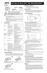
User Manual Back-UPS™ Connect BGE 70/70-CA 120 Vac Inventory Connect Equipment b u37 4a bu377a Safety and General Information Inspect the package contents upon receipt. Notify the carrier and dealer if there is any damage. Battery Backup Outlets Battery backup outlets provide protection to connected equipment when the Back-UPS is turned on and connected to AC power. Read the Safety Guide supplied with this unit before installing the UPS. • • • • • • Battery backup outlets receive power from the Back-UPS for a limited period of time when a power outage, or brownout condition occurs. This unit is designed for low power devices less than 75 Watts. When the UPS is on battery, the unit will shut down automatically to protect itself once the load on the UPS is greater than 75Watts. This UPS is intended for indoor use only. Do not operate this UPS in direct sunlight, in contact with fluids, or where there is excessive dust or humidity. Be sure the air vents on the UPS are not blocked. Allow adequate space for proper ventilation. The battery typically lasts for three to five years. Environmental factors impact battery life. Elevated ambient temperatures, poor quality AC power, and frequent short duration discharges will shorten battery life. Connect the UPS power cable directly to a wall outlet. Do not use surge protectors or extension cords. Output Protection and Filtering Battery Physical Connect a broadband modem and wireless router to the outlets. Voice over IP (VOIP) phones (if applicable) should also be plugged into battery backup outlets. To maximize runtime in the event of a power outage only connect networking equipment to battery backup outlets. This UPS is designed to sustain low power devices for extended periods of time. When the UPS is on battery, the unit will shut down automatically if the load on the UPS exceeds 75Watts. Low power devices include modems, routers, USB chargers (5W and 10W), VOIP and cordless phones. Turn On the Back-UPS Specifications Input Battery backup outlets provide protection from power surges or spikes. Voltage Frequency Brownout Transfers Over-voltage Transfer UPS Capacity (3 battery backup outlets) Total Amperage (all outlets) Voltage - On Battery Frequency - On Battery Transfer Time AC Surge Protection EMI/RFI Filter AC Input Type Press the POWER ON button located on the top of the Back-UPS. The Power On/ Replace Battery LED will illuminate and a single short beep will be audible to indicate that the Back-UPS is providing protection for connected equipment. 120 Vac Nominal 50/60 Hz + 3 92 Vac Typical 139 Vac Typical 125 VA, 75 W The Back-UPS battery charges fully during the first 16 hours while connected to AC power. The Back-UPS battery will charge while the Back-UPS is switched on or off and is connected to AC power. Do not expect full battery run capability during the initial charge time. 1.04 A (including UPS output) 115 Vac ± 8% 50/60 Hz + 1 6 ms Typical, 10 ms maximum Full time, 90 Joules Full time Resettable circuit breaker Sealed, maintenance-free, lead acid RBC153 Average Life 3 - 5 years depending on the number of discharge cycles and environmental temperature Net Weight 5.51 lb (2.5 kg) Dimensions 8.9 in x 4.1 in x 5.2 in Length x Width x Height 22.5 cm x 10.5 cm x 13.2 cm Operating Temperature 32º F to 104º F (0º C to 40º C) Storage Temperature 5º F to 113º F (–15º C to 45º C) Operating Relative Humidity 0 to 95% non-condensing humidity Operating Elevation 0 to 10,000 ft (0 to 3000 m) Status Indicators Connect the Battery bu375a The Back-UPS is shipped with one battery cable disconnected. 7 bu3 9a Press the battery compartment cover release tabs located on the rear side of the unit. Slide the battery cover off. Remove the “Stop! Connect the Battery” label that covers the outlets. Power Button LED Status Audible Audible Indicator Indicator On Terminates Power On The Back-UPS is supplying AC power to connected equipment. On Battery Back-UPS supplying battery power to battery backup outlets. The LED None illuminates green. The LED illuminates green. The LED flashes once at the end of every 2 seconds. Back-UPS beeps for 2 seconds when entering battery mode. Low Battery warning The Back-UPS is supplying battery power to the battery backup outlets and the battery is near a total discharge state. Replace Battery • The battery is disconnected. • The battery needs to be charged, or replaced. Overload Shutdown While on battery power an overload condition has occurred in one or more of the battery backup outlets while the Back-UPS is operating on battery power. Sleep Mode While on battery power the battery is completely discharged. The Back-UPS will “awaken” once AC power is restored. The LED illuminates green and flashes in rapid succession. The BackUPS emits rapid beeping, every 1/2 second. Constant tone N/A Beeping stops at the end of the first two seconds. A constant beep at the initial two seconds indicates the BackUPS has entered the battery mode. Beeping stops when AC power is restored or the BackUPS is turned off. The LED alternately illuminates greenConstant red. tone Back-UPS is turned off. None Constant tone Back-UPS is turned off. None The BackThe beeping stops UPS beeps when: once every • AC power is four seconds. restored • If AC power is not restored within 32 seconds • The Back-UPS is turned off Wall Mount Installation Connect the battery cable securely to the battery terminal. It is normal for small sparks to be seen when the battery cable is connected to the battery terminal. bu378a bu376a • • Reinstall the battery compartment cover. Be sure that the release tab locks into place. Horizontal installation, use 2 screws 3-15/16” (100 mm) apart. Allow 5/16” (8 mm), of the screw to protrude from the wall. 3 in. 100 mm Wall-mounting Template bu380a Voltage Sensitivity Adjustment (optional) The Back-UPS detects and reacts to line voltage distortions by transferring to battery backup power to protect connected equipment. In situations where either the Back-UPS or the connected equipment is too sensitive for the input voltage level it is necessary to adjust the transfer voltage. 1. Connect the Back-UPS to a wall outlet. The Back-UPS will be in Standby mode, no indicators will be illuminated. 2. Press and hold the ON/OFF button for 10 seconds. The OnLine LED will illuminate alternately green-red, to indicate that the Back-UPS is in Program mode. 3. The Power On/Replace Battery LED will flash either green, amber, or red to indicate the current sensitivity level. Refer to the table for an explanation of the transfer voltage sensitivity levels. 4. To select LOW sensitivity, press and hold the ON/OFF button until the LED flashes green. 5. To select MEDIUM sensitivity, press and hold the ON/OFF button until the LED flashes red. 6. To select HIGH sensitivity, press and hold the ON/OFF button until the LED flashes amber. 7. To exit Program mode wait five seconds and all LED indicators will extinguish. Program mode is no longer active. LED Flashes Sensitivity Setting Input Voltage Range (AC Operation) Recommended Use Green LOW 88 Vac to 142 Vac Use this setting with equipment that is less sensitive to fluctuations in voltage or waveform distortions. Red MEDIUM 92 Vac to 139 Vac Factory default setting. Use this setting under normal conditions. Amber HIGH 96 Vac to 136 Vac Use this setting when connected equipment is sensitive to voltage and waveform fluctuations. Troubleshooting Problem and Possible Cause Solution The Back-UPS has not been turned on. Press the POWER ON button. The Back-UPS is not connected to AC power, there is no AC power available at the wall outlet, or the AC power is experiencing a brownout or over voltage condition. Make sure the power cord is securely connected to the wall outlet, and that there is AC power available at the wall outlet.Where applicable, check that the wall outlet is switched on. The battery is not connected. Connect the battery. Refer to “Connect the Battery” on page 1 of this manual. In the event that the Back-UPS receives no AC power and the battery is connected, a cold-start can be initiated. Press and hold the Power On button until the Back-UPS emits two beeps. The Back-UPS is on, the Replace Battery LED flashes and the unit emits a constant tone Refer to the “Connect the Battery” on page 1. Connected equipment loses power A Back-UPS overload condition has occurred. Remove all nonessential equipment connected to the outlets. One at a time reconnect equipment to the Back-UPS. The Back-UPS battery is completely discharged. Connect the Back-UPS to AC power and allow the battery to recharge for eight hours. Connected equipment does not accept The output waveform is intended for computers the step-approximated sine waveform and peripheral devices. It is not intended for use with motor driven equipment. from the Back-UPS. The Back-UPS may require service. Deliver the used battery to a recycling facility. Replace the used battery with an APC by Schneider Electric approved battery. Replacement batteries can be ordered through the APC by Schneider Electric Web site, www.apc.com. Battery replacement part for Back-UPS BGE70 is APCRBC153. Service If the unit requires service, do not return it to the dealer. Follow these steps: 1. Review the Troubleshooting section of the manual to eliminate common problems. 2. If the problem persists, contact Schneider Electric IT (SEIT) Customer Support through the APC by Schneider Electric Web site, www.apc.com. a. Note the model number and serial number and the date of purchase. The model and serial numbers are located on the rear panel of the unit and are available through the LCD display on select models. b. Call SEIT Customer Support and a technician will attempt to solve the problem over the phone. If this is not possible, the technician will issue a Returned Material Authorization Number (RMA#). c. If the unit is under warranty, the repairs are free. d. Service procedures and returns may vary internationally. Refer to the APC by Schneider Electric Web site for country specific instructions. 3. Pack the unit in the original packaging whenever possible to avoid damage in transit. Never use foam beads for packaging. Damage sustained in transit is not covered under warranty. 4. Always DISCONNECT THE UPS BATTERIES before shipping. The United States Department of Transportation (DOT), and the International Air Transport Association (IATA) regulations require that UPS batteries be disconnected before shipping. The internal batteries may remain in the UPS. 5. Write the RMA# provided by Customer Support on the outside of the package. 6. Return the unit by insured, pre-paid carrier to the address provided by Customer Support Warranty The Back-UPS will not turn on The battery is disconnected. Replace Battery The standard warranty is three (3) years from the date of purchase. Schneider Electric IT (SEIT) standard procedure is to replace the original unit with a factory reconditioned unit. Customers who must have the original unit back due to the assignment of asset tags and set depreciation schedules must declare such a need at first contact with an SEIT Technical Support representative. SEIT will ship the replacement unit once the defective unit has been received by the repair department, or cross ship upon the receipt of a valid credit card number. The customer pays for shipping the unit to SEIT. SEIT pays ground freight transportation costs to ship the replacement unit to the customer. APC by Schneider Electric IT Customer Support Worldwide For country specific customer support, go to the APC by Schneider Electric Web site, www.apc.com. EMC Compliance This device complies with part 15 of the FCC rules. Operation is subject to the following two conditions: (1) This device may not cause harmful interference, and (2) This device must accept any interference received, including interference that may cause undesired operation. This UPS is certified to comply with California Battery Charger System regulations. For more information go to www.apc.com/site/recycle/index.cfm/energy-efficiency/cec-battery-charger/ Contact Schneider Electric IT (SEIT) Technical Support for more in depth troubleshooting. The Power On LED is illuminated and the Back-UPS beeps 4 times every 30 seconds The Back-UPS is operating on battery The Back-UPS is operating normally on battery power. power. At this point the user should save all open files, and shutdown the computer. When AC power is restored the battery will recharge. The Power On LED flashes once every second while the Back-UPS beeps once every second The Back-UPS battery has approximately two minutes of remaining runtime. The Back-UPS battery is near a total discharge state. At this point the user should save all open files, and shutdown the computer. When AC power is restored the battery will recharge. The Back-UPS has an inadequate battery runtime The battery is not fully charged. The battery is near the end of useful life and should be replaced. Leave the Back-UPS connected to AC power for 16 hours while the battery charges to full capacity. As a battery ages, the runtime capability decreases. Contact APC by Schneider Electric at the Web site www.apc.com, to order replacement batteries. The connection from the Back-UPS to the internet is lost during a power outage The modem has lost power. Connect the broadband modem into one of the Battery Backup + Surge Protection outlets. © 2013 APC by Schneider Electric. APC, the APC logo, and Back-UPS are owned by Schneider Electric Industries S.A.S., or their affiliated companies. All other trademarks are property of their respective owners. EN 990-5285 12/2013