1
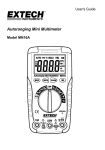
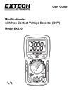
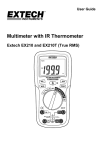
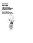
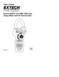
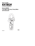
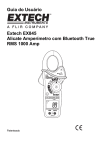
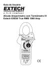
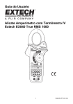
USER GUIDE Extech EX850 True RMS 1000 Amp Clamp Meter BluetoothTM and AndroidTM ready Patented EXTECH INSTRUMENTS Introduction Congratulations on your purchase of the Extech EX850 CAT IV True RMS 1000A Clamp Meter. This meter includes a BluetoothTM module and is AndroidTM ready. The EX850 measurement functions include AC/DC Voltage, AC/DC Current, Resistance, Capacitance, Frequency, Duty Cycle, Diode Test, Continuity, Type k thermocouple thermometer plus Non‐Contact IR Temperature. Proper use and care of this meter will provide many years of reliable service. Visit www.extech.com for more information. Safety International Safety Symbols This symbol, adjacent to another symbol or terminal, indicates the user must refer to the manual for further information. This symbol, adjacent to a terminal, indicates that, under normal use, hazardous voltages may be present Double insulation SAFETY NOTES Do not exceed the maximum allowable input range of any function. Do not apply voltage to meter when resistance function is selected. Set the function switch OFF when the meter is not in use. Remove the battery if meter is to be stored for longer than 60 days. WARNINGS Set function switch to the appropriate position before measuring. When measuring volts do not switch to current/resistance modes. Do not measure current on a circuit whose voltage exceeds 600V. When changing ranges always disconnect the test leads from the circuit under test. Function Maximum Input A AC, ADC 1000A DC/AC V DC, V AC 1000V DC/AC Resistance, Capacitance, Frequency, Diode Test 250V DC/AC Type K Temperature 60V DC, 24V AC 2 EX850-EN V2.1 4/14 EXTECH INSTRUMENTS CAUTIONS Improper use of this meter can cause damage, shock, injury or death. Read and understand this user manual before operating the meter. Always remove the test leads before replacing the battery or fuses. Inspect the condition of the test leads and the meter itself for any damage before operating the meter. Repair or replace any damage before use. Use great care when making measurements if the voltages are greater than 25VAC rms or 35VDC. These voltages are considered a shock hazard. Always discharge capacitors and remove power from the device under test before performing Diode, Resistance or Continuity tests. Voltage checks on electrical outlets can be difficult and misleading because of the uncertainty of connection to the recessed electrical contacts. Other means should be used to ensure that the terminals are not "live". If the equipment is used in a manner not specified by the manufacturer, the protection provided by the equipment may be impaired. This device is not a toy and must not reach children’s hands. It contains hazardous objects as well as small parts that the children could swallow. In case a child swallows any of them, please contact a physician immediately Do not leave batteries and packing material lying around unattended; they can be dangerous for children if they use them as toys In case the device is going to be unused for an extended period of time, remove the batteries to prevent them from draining Expired or damaged batteries can cause cauterization on contact with the skin. Always, therefore, use suitable hand gloves in such cases See that the batteries are not short‐circuited. Do not throw batteries into the fire. Do not directly view or direct the laser pointer at an eye. Low power visible lasers do not normally present a hazard, but may present some potential for hazard if viewed directly for extended periods of time 3 EX850-EN V2.1 4/14 EXTECH INSTRUMENTS Description Meter Description 1. 2. 3. 4. 5. 6. 7. 8. 9. 10. 11. 12. 13. 14. Current clamp Clamp opening trigger Data Hold Button Mode Peak Range DCA Zero MIN/MAX Backlit LCD Display Test lead input jacks IR thermometer and laser pointer (rear) Bluetooth SEND/Backlight Button Laser pointer button Function switch Display icons Description HOLD Minus sign 0 to 3999 ZERO P AUTO DC/AC MAX MIN Data Hold Negative reading display Measurement display digits Zero Peak value Auto Range mode Direct / Alternating Current Max reading Min reading Low battery mV or V Milli‐volts or Volts (Voltage) Ω Ohms (Resistance) A Amperes (Current) Farad (Capacitance) F Hz Hertz (Frequency) o F and oC Fahrenheit and Celsius units (Temperature) n, m, µ, M, k Unit of measure prefixes: nano, milli, micro, mega, and kilo ))) Continuity test Diode test Laser pointer Bluetooth active symbol 4 EX850-EN V2.1 4/14 EXTECH INSTRUMENTS Operation NOTES: Read and understand all Warning and Caution statements in this operation manual prior to using this meter. Set the function select switch to the OFF position when the meter is not in use. AC Current Measurements WARNING: Ensure that the test leads are disconnected from the meter before making current clamp measurements. 1. Set the Function switch to the AAC or ADC range 2. Press the trigger to open the jaw. Fully enclose only one conductor. For optimum results, center the conductor in the jaw. 3. The clamp meter LCD will display the reading. DCA ZERO The DC Zero feature removes offset values and improves accuracy for DC current measurements. To perform a zero, select ADC and with no conductor in the jaw: Incorrect Correct 1. Press the DC ZERO button to zero the display. “ZERO” will appear in the display. The offset value is now stored and remo ved from all measurements. 2. To view the stored value, press the DC ZERO button. “ZERO” will flash and the stored value will be displayed. 3. To exit this mode, press and Hold the ZERO button until “ZERO” is no longer in the display. AC/DC Voltage Measurements 1. Insert the black test lead into the negative COM terminal and the red test lead into the positive V terminal. 2. Set the function switch to the VAC or VDC position. 3. Use the MODE button to select AC or DC Voltage. 4. Connect the test leads in parallel to the circuit under test. 5. Read the voltage measurement on the LCD display. 5 EX850-EN V2.1 4/14 EXTECH INSTRUMENTS Resistance Measurements Note: Remove power before making resistance measurements 1. Insert the black test lead into the negative COM terminal and the red test lead into the Ω positive terminal. 2. Set the function switch to the Ω position. 3. Touch the test probe tips across the circuit or component under test. 4. Read the resistance on the LCD display. Capacitance Measurements WARNING: To avoid electric shock, discharge the capacitor under test before measuring. If “dISC” appears in the display, remove and discharge the capacitor. Ù Ω capacitance position. 1. Set the function switch to the 2. Insert the black test lead banana plug into the negative COM jack and the red test lead banana plug into the CAP positive jack. 3. Press MODE to zero any stray capacitance. 4. Touch the test probe tips across the part under test. 5. Read the capacitance value in the display. 6. The display will indicate the proper decimal point and value. Note: For very large values of capacitance measurement time can be several minutes before the final reading stabilizes. CAP Frequency Measurements 1. Set the function switch to the V Hz Position. 2. Press and hold the MODE button to select the Frequency (Hz) function. “k Hz” will appear in the display. 3. Insert the black test lead banana plug into the negative COM jack and the red test lead banana plug into the Hz positive jack. 4. Touch the test probe tips across the part under test. 5. Read the Frequency value on the display. 6. The display will indicate the proper decimal point and value. 7. Press and hold the MODE button again to return to the voltage mode 6 Hz EX850-EN V2.1 4/14 EXTECH INSTRUMENTS Type K Temperature Measurements 1. Set the function switch to the K Temp position. 2. Insert the Temperature Probe into the negative COM and the positive TEMP jacks, observing polarity. 3. Touch the Temperature Probe tip to the device under test. Continue to touch the part under test with the probe until the reading stabilizes. 4. Read the temperature on the display. The digital reading will indicate the proper decimal point and value. WARNING: To avoid electric shock, be sure the thermocouple probe has been removed before changing to another measurement function. Note: Open inputs or temperature over‐ranges cause “OL” display and beep. Note: See the “Temperature Units” paragraph to select °F or °C Note: The temperature range of the supplied thermocouple probe is ‐20 to 250°C (‐4 to 482°F) Continuity Measurements 1. Insert the black test lead into the negative COM terminal and the red test lead into the Ω positive terminal. 2. Set the function switch to the ))) position. 3. Use the MODE button to select continuity ))). The display icons will change when the MODE button is pressed. 4. Touch the test probe tips across the circuit or component under test. 5. If the resistance is < 40 Ω, a tone will sound. Diode Test 1. Insert the black test lead banana plug into the negative COM jack and the red test lead banana plug into the positive jack 2. Turn the function switch to position. Use the MODE button to select the diode function if necessary (diode symbol will appear on the LCD when in Diode test mode) 3. Touch the test probe tips to the diode or semiconductor junction under test. Note the meter reading 4. Reverse the test lead polarity by reversing the red and black leads. Note this reading 5. The diode or junction can be evaluated as follows: If one reading displays a value (typically 0.400V to 0.900V) and the other reading displays OL, the diode is good. If both readings display OL the device is open. If both readings are very small or ‘0’, the device is shorted. 7 EX850-EN V2.1 4/14 EXTECH INSTRUMENTS Non‐Contact InfraRed Temperature Measurements 1. 2. 3. 4. 5. Set the function switch to the IR Temp position. Aim the infrared sensor (rear of the meter) at the surface to be measured. Press the button in the center of the rotary function switch to turn on the laser pointer and identify the surface spot to be measured. The area of the surface to be measured must be larger than the spot size as determined by the distance to spot size specification. Read the temperature in the display. Note: See the “Temperature Units” paragraph to select oF or oC WARNING: Do not directly view or direct the laser pointer at an eye. Low power visible lasers do not normally present a hazard, but may present some potential for hazard if viewed directly for extended periods of time. IR Spot to Distance Diagram The 8:1 spot to distance ratio determines the size of the measured surface area with respect to the distance the meter is held away from the surface. Diameter of spot 2.5cm 1.25cm 7.5cm 10cm 20cm 60cm Distance to object IR Measurement Notes 1. The object under test should be larger than the spot (target) size calculated by the field of view diagram. 2. If the surface of the object under test is covered with frost, oil, grime, etc., clean before taking measurements. 3. If an object's surface is highly reflective, apply masking tape or flat black paint to the surface before measuring. 4. The meter may not make accurate measurements through transparent surfaces such as glass. 5. Steam, dust, smoke, etc. can obscure measurements. 6. To find a hot spot, aim the meter outside the area of interest then scan across (in an up and down motion) until the hot spot is located. 8 EX850-EN V2.1 4/14 EXTECH INSTRUMENTS Data Hold To freeze the LCD reading, press the HOLD button. While data hold is active, the HOLD icon appears on the LCD. Press the HOLD button again to return to normal operation. Peak Hold The Peak Hold function captures the peak AC or DC voltage or current. The meter can capture negative or positive peaks as fast as 1 millisecond in duration. 1. Turn the function switch to the A or V position. 2. Use the MODE button to select AC or DC 3. Allow time for the display to stabilize. 4. Press and Hold the PEAK button until “CAL” appears in the display. This procedure will zero the range selected. 5. Press the PEAK button, Pmax will display. 6. The display will update each time a higher positive peak occurs. 7. Press the PEAK button again, Pmin will display. The display will now update and indicate the lowest negative peak. 8. To return to normal operation, press and hold the PEAK button until the Pmin or Pmax indicator switches off. Note: If the Function switch position is changed after a calibration the Peak Hold calibration must be repeated for the new function selected. MAX/MIN 1. 2. 3. 4. Press the MAX/MIN key to activate the MAX/MIN recording mode. The display icon "MAX" will appear. The meter will display and hold the maximum reading and will update only when a new “max” occurs. Press the MAX/MIN key and the display icon "MIN" will appear. The meter will display and hold the minimum reading and will update only when a new “min” occurs Press the MAX/MIN key and a blinking “MAX MIN” will appear. The meter will display the present reading, but will continue to update and store the max and min readings. To exit MAX/MIN mode press and hold the MAX/MIN key for 2 seconds. Units Switch F C Temperature Units (˚F / ˚C) The temperature unit selection switch is located in the battery compartment. To change the units, remove the battery door, lift out the battery and set the switch for the desired units. LCD Backlight Button The LCD is equipped with backlighting for easier viewing, especially in dimly lit areas. Press the backlight button to turn the backlight on. Press again to turn the backlight off. 9 EX850-EN V2.1 4/14 EXTECH INSTRUMENTS Automatic Power OFF In order to conserve battery life, the meter will automatically turn off after approximately 10 minutes. To turn the meter on again, turn the function switch to the OFF position and then to the desired function position. BluetoothTM Communication The meter includes a Bluetooth module. Enable the EX850 Bluetooth by pressing and holding the side Bluetooth SEND/Backlight button for two seconds. On the second beep the Bluetooth icon will appear in the display. AndroidTM Applications The EX850 meter is Android ready. Follow the steps below to obtain the Android application ExView EX850 and to connect to the meter with an Android device. 1. Obtain and install the Android ExView EX850 application from the Google Play Store. 2. Perform a search to obtain the EX850 from the list of available devices. 3. Pair the meter with the Android device (pad, tablet, phone, etc.) in Settings under Bluetooth. 4. Start the ExView EX850 application, tap CONNECT and the paired list will appear. Select the EX850 meter from the paired list. 5. The meter will begin communicating and Meter readings will appear on the Android device. 6. The user can select the meter’s measurement mode directly from the icons shown on the bottom row of the Android device (V, A, mA, A, etc.). Simply tap the desired measurement parameter to view the readings. Refer to the screen shots below. Note: If several meters are to be used, be sure to note the unique address of each meter to quickly discern which meter is displaying at any given time. Android Application Screen Shot Examples AC Current AC Voltage 10 EX850-EN V2.1 4/14 EXTECH INSTRUMENTS FCC COMPLIANCE FCC ID: IWK‐EX850 This device complies with part 15 of the FCC Rules. Operation is subject to the following two conditions: 1. This device may not cause harmful interference. 2. This device must accept any interference received, including interference that may cause undesired operation. This equipment has been tested and found to comply with the limits for a Class B digital device, pursuant to part 15 of the FCC Rules. These limits are designed to provide reasonable protection against harmful interference in a residential installation. This equipment generates, uses, and can radiate radio frequency energy harmful interference to radio communications. However, there is no guarantee that interference will not occur in a particular installation. If this equipment does cause harmful interference to radio or television reception, which can be determined by turning the equipment off and on, the user is encouraged to try to correct the interference by one or more of the following measures: • Reorient or relocate the receiving antenna. • Increase the separation between the equipment and receiver. • Connect the equipment into an outlet on a circuit different from that to which the receiver is connected. • Consult the dealer or an experienced radio/TV technician for help. CAUTION: Exposure to Radio Frequency Radiation To comply with FCC/IC RF exposure compliance requirements, a separation distance of at least 20 cm must be maintained between the antenna of this device and all persons. This device must not be co‐located or operating in conjunction with any other antenna or transmitter. WARNING: Changes or modifications not expressly approved by the party responsible for compliance could void the user's authority to operate the equipment. 11 EX850-EN V2.1 4/14 EXTECH INSTRUMENTS INDUSTRY CANADA (IC) COMPLIANCE IC ID: 1590A‐EX850 This device complies with Industry Canada license‐exempt RSS standard(s). Operation is subject to the following two conditions: (1) this device may not cause interference, and (2) this device must accept any interference, including interference that may cause undesired operation of the device. CAUTION: Exposure to Radio Frequency Radiation. To comply with RSS 102 RF exposure compliance requirements, for mobile configurations, a separation distance of at least 20 cm must be maintained between the antenna of this device and all persons. This device must not be collocated or operating in conjunction with any other antenna or transmitter. Maintenance WARNING: To avoid electrical shock, disconnect the meter from any circuit, remove the test leads from the input terminals, and turn OFF the meter before opening the case. Do not operate the meter with an open case. Cleaning and Storage Periodically wipe the case with a damp cloth and mild detergent; do not use abrasives or solvents. If the meter is not to be used for 60 days or more, remove the battery and store it separately. Battery Replacement 1. Remove the Phillips head screw that secures the rear battery door 2. Open the battery compartment 3. Replace the 9V battery 4. Secure the battery compartment 12 EX850-EN V2.1 4/14 EXTECH INSTRUMENTS Specifications Function Range & Resolution AC Current 50/60 Hz 400.0 AAC ± (2.5% + 8d) 1000 AAC ± (2.8% + 5d) 400.0 ADC ± (2.5% + 5d) 1000 ADC ± (2.8% + 5d) 400.0 mVAC ± (1.0% + 10d) DC Current AC Voltage 4.000 VAC 50/60Hz 40.00 VAC Accuracy (% of reading + digits) ± (1.5% + 5d) 400.0 VAC 1000 VAC ± (2.0% + 5d) 400.0 mVDC ± (0.8% + 2d) 4.000 VDC DC Voltage ± (1.5% + 2d) 40.00 VDC 400.0 VDC 1000 VDC ± (2.0% + 2d) 400.0Ω ± (1.0% + 4d) 4.000kΩ Resistance 40.000kΩ ± (1.5% + 2d) 400.0kΩ 4.000MΩ ± (2.5% + 3d) 40.00MΩ ± (3.5% + 5d) 4.000nF ± (5.0% + 30d) 40.00nF ± (5.0% + 20d) 400.0nF Capacitance 4.000µF ± (3.0% + 5d) 40.00µF Frequency 400.0µF ± (4.0% + 10d) 4.000mF ± (10% + 10d) 40.00mF unspecified 4.000kHz ± (1.5% + 2d) Sensitivity: 100V (<50Hz); 50V (50 to 400Hz); 5V (401Hz to 4000Hz) 13 EX850-EN V2.1 4/14 EXTECH INSTRUMENTS Function Range and Resolution Temperature (type‐K) Temp (IR) Clamp jaw opening Display Continuity check Diode test Low Battery indication Over‐range indication Measurement rate Bluetooth range PEAK Thermocouple sensor IR Spectral response IR Emissivity IR distance ratio Input Impedance AC bandwidth AC response Crest Factor Operating Temperature Storage Temperature Operating Humidity Storage Humidity Operating Altitude Battery Auto power OFF Dimensions & Weight Safety Patent notice Accuracy (% of reading + digits) o ‐4 to 1400 F ± (3%rdg + 9oF) ‐20 to 760oC ± (3%rdg + 5oC) ‐58 to ‐4F 9 F ‐4 to 518F 2.0% reading or 4F whichever is > ‐50 to ‐20C 5C ‐20 to 270C 2.0% reading or 2C whichever is > 1.7" (43mm) approx. 3‐3/4 digits (4000 counts) backlit LCD Threshold 40; Test current < 0.5mA Test current of 0.3mA typical; Open circuit voltage < 3VDC typical Battery symbol is displayed ‘OL’ display 2 readings per second, nominal 32 feet (10 meters) approximately Captures peaks >1ms Type K thermocouple required 6 to 16µm 0.95 fixed 8:1 10M (VDC and VAC) 50 to 400Hz (AAC and VAC) True rms (AAC and VAC) 3.0 in 40A and 400A ranges, 1.4 in 1000A range (50/60Hz and 5% to 100% of range) 41F to 104F (5C to 40C) ‐4F to 140F (‐20C to 60C) Max 80% up to 87F (31C) decreasing linearly to 50% at 104F (40C) <80% 7000ft. (2000meters) maximum One (1) 9V Battery (NEDA 1604) After approx. 10 minutes 10.6x4.3x2” (270x110x50mm); 13.6 oz. (386g) For indoor use and in accordance with the requirements for double insulation to IEC1010‐1 (2001): EN61010‐1 (2001) Overvoltage Category IV 600V and Category III 1000V, Pollution Degree 2. U.S. Patent 7163336 14 EX850-EN V2.1 4/14 EXTECH INSTRUMENTS Warranty FLIR Systems, Inc. warrants this Extech Instruments brand device to be free of defects in parts and workmanship for one year from date of shipment (a six month limited warranty applies to sensors and cables). If it should become necessary to return the instrument for service during or beyond the warranty period, contact the Customer Service Department for authorization. Visit the website www.extech.com for contact information. A Return Authorization (RA) number must be issued before any product is returned. The sender is responsible for shipping charges, freight, insurance and proper packaging to prevent damage in transit. This warranty does not apply to defects resulting from action of the user such as misuse, improper wiring, operation outside of specification, improper maintenance or repair, or unauthorized modification. FLIR Systems, Inc. specifically disclaims any implied warranties or merchantability or fitness for a specific purpose and will not be liable for any direct, indirect, incidental or consequential damages. FLIR’s total liability is limited to repair or replacement of the product. The warranty set forth above is inclusive and no other warranty, whether written or oral, is expressed or implied. Calibration, Repair, and Customer Care Services FLIR Systems, Inc. offers repair and calibration services for the Extech Instruments products we sell. NIST certification for most products is also provided. Call the Customer Service Department for information on calibration services available for this product. Annual calibrations should be performed to verify meter performance and accuracy. Technical support and general customer service is also provided, refer to the contact information provided below. Support Lines: U.S. (877) 439‐8324; International: +1 (603) 324‐7800 Technical Support: Option 3; E‐mail: [email protected] Repair & Returns: Option 4; E‐mail: [email protected] Product specifications are subject to change without notice Please visit our website for the most up‐to‐date information www.extech.com FLIR Commercial Systems, Inc., 9 Townsend West, Nashua, NH 03063 USA ISO 9001 Certified Copyright © 2014 FLIR Systems, Inc. All rights reserved including the right of reproduction in whole or in part in any form www.extech.com 15 EX850-EN V2.1 4/14 EXTECH INSTRUMENTS Garantie FLIR Systems, Inc. garantit que cet appareil Extech Instruments est exempt de défauts matériaux et de fabrication pendant un an à partir de la date d’envoi (une garantie limitée de six mois s’applique aux capteurs et aux câbles). Si le renvoi de l’appareil pour réparation devient nécessaire durant ou après la période de garantie, contactez le service client pour autorisation. Pour obtenir les coordonnées, visitez le site Web suivant : www.extech.com. Un numéro d’autorisation de retour (AR) doit être délivré avant tout retour de produit. L’expéditeur prend à sa charge les frais d’expédition, le fret, l’assurance et l’emballage correct de l’appareil afin de prévenir toute détérioration durant le transport. Cette garantie ne s’applique pas aux dommages imputables à l’utilisateur, tels que l’usage impropre ou abusif, un mauvais câblage, une utilisation non conforme aux spécifications, un entretien ou une réparation incorrecte, ou toute modification non autorisée. FLIR Systems, Inc. déclinera spécifiquement toute garantie ou qualité marchande ou aptitude à l’emploi prévu, et ne sera en aucun cas tenu responsable pour tout dommage conséquent, direct, indirect ou accidentel. La responsabilité totale de FLIR est limitée à la réparation ou au remplacement du produit. La garantie définie ci‐dessus est inclusive et aucune autre garantie, écrite ou orale, n’est exprimée ou implicite. Calibrage, réparation et services après‐vente FLIR Systems, Inc. offre des services de calibrage et de réparation pour les produits Extech Instruments que nous commercialisons. Nous fournissons également une certification NIST pour la plupart des produits. Contactez notre service client pour toute information sur les services de calibrage disponibles pour ce produit. Un calibrage doit être effectué chaque année pour vérifier les performances et la précision du mètre. Nous offrons également une assistance technique et un service à la clientèle. Veuillez vous reporter aux coordonnées fournies ci‐dessous. Lignes d’assistance : États‐Unis (877) 439‐8324 ; international : +1 (603) 324‐7800 Service d’assistance technique : Option 3 ; E‐mail : [email protected] Réparations et retours : Option 4 ; E‐mail : [email protected] Les spécifications produit sont sujettes à modifications sans préavis. Pour les toutes dernières informations, veuillez visiter notre site Web. www.extech.com FLIR Commercial Systems, Inc., 9 Townsend West, Nashua, NH 03063 USA Certifié ISO 9001 Copyright © 2014 FLIR Systems, Inc. Tous droits réservés, y compris la reproduction partielle ou totale sous quelque forme que ce soit. www.extech.com 16 EX850-EN V2.1 4/14 EXTECH INSTRUMENTS Garantía FLIR Systems, Inc., garantiza este dispositivo marca Extech Instruments para estar libre de defectos en partes o mano de obra durante un año a partir de la fecha de embarque (se aplica una garantía limitada de seis meses para cables y sensores). Si fuera necesario regresar el instrumento para servicio durante o después del periodo de garantía, llame al Departamento de Servicio a Clientes para obtener autorización. Visite www.extech.com para Información de contacto. Se debe expedir un número de Autorización de Devolución (AD) antes de regresar cualquier producto. El remitente es responsable de los gastos de embarque, flete, seguro y empaque apropiado para prevenir daños en tránsito. Esta garantía no se aplica a defectos resultantes de las acciones del usuario como el mal uso, alambrado equivocado, operación fuera de las especificaciones, mantenimiento o reparación inadecuada o modificación no autorizada. FLIR Systems, Inc., rechaza específicamente cualesquier garantías implícitas o factibilidad de comercialización o idoneidad para cualquier propósito determinado y no será responsable por cualesquier daños directos, indirectos, incidentales o consecuentes. La responsabilidad total de FLIR está limitada a la reparación o reemplazo del producto. La garantía precedente es inclusiva y no hay otra garantía ya sea escrita u oral, expresa o implícita. Servicios de calibración, reparación y atención a clientes FLIR Systems, Inc., ofrece servicios de reparación y calibración para los productos que vendemos de Extech Instruments. Además ofrecemos certificación NIST para la mayoría de los productos. Llame al Departamento de Servicio al Cliente para solicitar información de calibración para este producto. Para verificar el funcionamiento y precisión se debe realizar la calibración anual. Además se provee Soporte Técnico y servicios generales al cliente, consulte la información de contacto en seguida. Líneas de soporte: EE.UU. (877) 439‐8324; Internacional: +1 (603) 324‐7800 Soporte Técnico Opción 3; correo electrónico: [email protected] Reparación / Devoluciones: Opción 4; correo electrónico: [email protected] Las especificaciones del producto están sujetas a cambios sin aviso Por favor visite nuestra página en Internet para la información más actualizada www.extech.com FLIR Commercial Systems, Inc., 9 Townsend West, Nashua, NH 03063 USA Certificado ISO 9001 Copyright © 2014 FLIR Systems, Inc. Reservados todos los derechos, incluyendo el derecho de reproducción total o parcial en cualquier medio www.extech.com 17 EX850-EN V2.1 4/14