1
M68KVSDM/D1
VME/10
Microcomputer System
Diagnostics Manual
QUALITY
•
PEOPLE
•
PERFORMANCE
M68KVSDM/Dl
OCTOBER 1983
VME/10 MICROCOMPUTER SYSTEM
DIAGNOSTICS MANUAL
The information in this document has been carefully checked and is believed to
entirely reliable. However, no responsibility is asswned for inaccuracies.
Furthermore, Motorola reserves the right to make changes to any products herein
to improve reliability, function, or design.
Motorola does not asswne any
liability arising out of the application or use of any product or circuit
described herein; neither does it convey any license under its patent rights or
the rights of others.
be
TENbug, VERSAdos, and VME/10 are trademarks of Motorola Inc.
First Edition
Copyright 1983 by Motorola Inc.
PREFACE
Unless otherwise specified, all address references are in hexadecimal
throughout this manual.
asterisk (*) following the signal name for signals which are level
significant denotes that the signal is true or valid when the signal
is low.
An
asterisk (*) followirg the signal name for signals which are edge
significant denotes that the actions initiated by that signal occur
on a high to low transition.
An
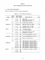
TABLE OF CONTENTS
CHAPTER 1
1.1
1.2
1.3
1.3.1
1.3.2
1.3.2.1
1.3.2.2
1.3.2.3
1.4
1.4.1
1.4.2
1.4.3
1.5
1.6
CHAPTER 2
2.1
2.2
2.3
2.4
2.5
2.5.1
2.5.2
2.5.3
2.5.4
2.5.5
2.5.6
2.5.7
2.6
2.6.1
2.6.2
2.6.3
2.6.4
CHAPTER 3
3.1
3.2
3.3
3.4
3.5
3.5.1
3.5.2
3.5.3
3.5.4
3.5.5
3.5.6
3.5.7
3.5.8
3.5.9
3.5.10
DIAGNOSTICS TEST PHILOSOPHY
INTRODUCI'ION ••••••••••••••••••••••••••••••••••••••••••••••
FAULT CATEGORIES ••••••••••••••••••••••••••••••••••••••••••
SYSTEM DIAGNOSTICS DESCRIPTION••••••••••••••••••••••••••••
Power-Up/Reset Self-Test (PWRT) •••••••••••••••••••••••••
Disk Resident Module Diagnostics Tests (DRMD) •••••••••••
User Carmands •••••••••••••••••••••••••••••••••••••••••
Startir:g DRMD Tests •••••••••••••••••••••••••••••••••••
Aborting D~ Tests
DISK RESIDENT TEST PHASES •••••••••••••••••••••••••••••••••
Mode Selection Phase
Test Execution Phase
Control Phase
DRMD DIAGNOSTIC LOOP
D™D STATUS LINE ••••••••••••••••••••••••••••••••••••••••••
...................................
....................................
...........................................
1-1
1-1
1-2
1-2
1-2
1-3
1-3
1-3
1-4
1-4
1-5
1-6
1-7
1-8
POWER-UP/RESET SELF-TEST
INTRODUCI'ION ••••••••••••••••••••••••••••••••••••••••••••••
SYSTEM CONFIGURATION ••••••••••••••••••••••••••••••••••••••
START/RESTART/ABORT INFORMATION •••••••••••••••••••••••••••
TEST RESULTS••••••••••••••••••••••••••••••••••••••••••••••
BATCH LEVEL TESTS •••••••••••••••••••••••••••••••••••••••••
Temporary Stack
CRT Controller (CR'IC)
Low RAM
...................................
Display RAM •••••••••••••••••••••••••••••••••••••••••••••
Character arrl Attribute Generator RAM •••••••••••••••••••
MPU
Firmware
MULTITASKED TESTS •••••••••••••••••••••••••••••••••••••••••
Time-of-Day Clock (TrX:) •••••••••••••••••••••••••••••••••
Enhanced Peripheral Controller Interface (EPCI) •••••••••
.....................................................
................................................
System RAM ••••••••••••••••••••••••••••••••••••••••••••••
Winchester Disk Controller (WIX:) ••••••••••••••••••••••••
2-1
2-1
2-1
2-1
2-2
2-2
2-2
2-2
2-2
2-3
2-3
2-3
2-4
2-4
2-4
2-4
2-5
SYSTEM CONTROLLER MODULE DISK RESIDENT MODULE DIAGNOSTIC TEST
INTRODUCTION ••••••••••••••••••••••••••••••••••••••••••••••
SYSTEM CONFIGURATION••••••••••••••••••••••••••••••••••••••
START/RESTART/ABORT INFORMATION •••••••••••••••••••••••••••
TEST RESULTS••••••••••••••••••••••••••••••••••••••••••••••
FUNCTIONAL DESCRIPTION ••••••••••••••••••••••••••••••••••••
MPU
TENbug Checksum Test ••••••••••••••••••••••••••••••••••••
~ory Test ............................................. .
Pixel Access Test •••••••••••••••••••••••••••••••••••••••
VMEbus Interface
Enhanced Peripheral Controller Interface (EPCI) •••••••••
Time-of-Day Clock (TDC)
Graphic Cursor
Abort Switch ••••••••••••••••••••••••••••••••••••••••••••
Reset Switch ••••••••••••••••••••••••••••••••••••••••••••
.....................................................
........................................
..........................................
i
3-1
3-1
3-1
3-1
3-1
3-2
3-2
3-2
3-3
3-3
3-3
3-4
3-4
3-4
3-5
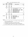
TABLE OF CONTENTS (cont'd)
CHAPTER 4
4.1
4.2
4.3
4.4
4.5
CHAPTER 5
5.1
5.2
5.3
5.4
5.5
5.5.1
5.5.2
5.5.3
5.5.4
5.5.5
5.5.6
5.5.7
5.5.8
5.5.9
5.5.10
5.5.11
5.5.12
5.5.13
5.5.14
5.5.15
5.5.16
CHAPTER 6
6.1
6.2
6.3
6.4
6.5
6.5.1
6.5.2
6.5.3
6.5.4
6.5.5
6.5.6
KEYBOARD DISK RESIDENT MODULE DIAGNOSTICS TEST
INTRODUCTION••••••••••••••••••••••••••••••••••••••••••••••
SYSTEM CONFIGURATION ••••••••••••••••••••••••••••••••••••••
START/RESTART/ABORT INFORMATION•••••••••••••••••••••••••••
TEST RESULTS ••••··~··•••••••••••••••••••••••••••••••••••••
F~TIONAL DESCRIPTION ••••••••••••••••••••••••••••••••••••
4-1
4-1
4-1
4-1
4-1
WINCHESTER DISK CONTROLLER
DISK RESIDENT MODULE DIAGNOSTICS TEST
INTRODUcrION ••••••••••••••••••••••••••••••••••••••••••••••
SYSTEM CONFIGURATION••••••••••••••••••••••••••••••••••••••
START/RESTART/ABORT INFORMATION •••••••••••••••••••••••••••
TEST RESULTS ••••••••••••••••••••••••••••••••••••••••••••••
FUNCTIONAL DESCRIPTION ••••••••••••••••••••••••••••••••••••
Drive Selection •••••••••••••••••••••••••••••••••••••••••
Reset Self-Test •••••••••••••••••••••••••••••••••••••••••
FIFO Host Port ••••••••••••••••••••••••••••••••••••••••••
Drive Status ••••••••••••••••••••••••••••••••••••••••••••
Drive Recalibrate •••••••••••••••••••••••••••••••••••••••
Track 0 Scan ••••••••••••••••••••••••••••••••••••••••••••
Sector 0 Read
Drive Configuration •••••••••••••••••••••••••••••••••••••
Drive Forward Sequential Scan •••••••••••••••••••••••••••
Rarrlom Sector Seek and Recalibrate ••••••••••••••••••••••
WDC Interrupts ••••••,••••••••••••••••••••••••••••••••••••
Diagnostics Track Set-up ••••••••••••••••••••••••••••••••
Diagnostics Data Verification •••••••••••••••••••••••••••
Data Write/Read •••••••••••••••••••••••••••••••••••••••••
Rarrlan Write ••••••••••••••••••••••••••••••••••••••••••••
Diagnostics Data Initialization •••••••••••••••••••••••••
...........................................
5-1
5-1
5-1
5-1
5-2
5-2
5-3
5-3
5-3
5-3
5-4
5-4
5-4
5-4
5-5
5-5
5-5
5-5
5-6
5-6
5-6
DUAL SERIAL PORT I/O MODULE
DISK RESIDENT MODULE DIAGNOSTICS TEST
INTRODUcrION ••••••••••••••••••••••••••••••••••••••••••••••
SYSTEM CONFIGURATION ••••••••••••••••••••••••••••••••••••••
START/RESTART/ABORT INFORMATION•••••••••••••••••••••••••••
TEST RESULTS ••••••••••••••••••••••••••••••••••••••••••••••
FUNCTIONAL DESCRIPTION ••••••••••••••••••••••••••••••••••••
M:>dule Existence Test •••••••••••••••••••••••••••••••••••
Module Initialization •••••••••••••••••••••••••••••••••••
Port 1 arrl 2 Control Lines ••••••••••••••••••••••••••••••
Port 1 and 2 Data Test ••••••••••••••••••••••••••••••••••
7201 Interrupts •••••••••••••••••••••••••••••••••••••••••
FAIL LED Test •••••••••••••••••••••••••••••••••••••••••••
ii
6-1
6-1
6-1
6-1
6-1
6-1
6-2
6-2
6-2
6-2
6-2
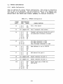
TABLE OF CONTENTS (cont'd)
CHAPTER 7
7.1
7. 2
7.3
7.4
7 .5
7.5.1
7.5.2
7.5.3
7.5.4
CHAPTER 8
8.1
8.2
8.2.1
8.2.2
8.3
8.3.1
8.3.2
DUAL PARALLEL PORT I/O MODULE
DISK RESIDENT MODULE DIAGNOSTICS TEST
INTRODUCTION ..............................................
SYSTEM a:>NFIGURATION • • • • • • • • • • • • • • • • • • • • • • • • • • • • • • • • • • • • • •
START/RESTART/ABORT INFORMATION •••••••••••••••••••••••••••
TEST RESULTS ..............................................
FUNCTIONAL DESCRIPTION • • • • • • • • • • • • • • • • • • • • • • • • • • • • • • • • • • • •
Port 1 and 2 Existence Test •••••••••••••••••••••••••••••
Port 1 and 2 Data Tests •••••••••••••••••••••••••••••••••
Port 1 and 2 Interrupt Tests ••••••••••••••••••••••••••••
FAIL LED Test ...........................................
7-1
7-1
7-1
7-1
7-1
7-1
7-2
7-2
7-2
VME/10 SYSTEM CONFIGURATION
BASIC SYSTEM CONFIGURATION ••••••••••••••••••••••••••••••••
MVME400 CONFIGURATION •••••••••••••••••••••••••••••••••••••
Module Configuration ••••••••••••••••••••••••••••••••••••
Loop Back Test Cable ••••••••••••••••••••••••••••••••••••
MVME410 (X)NFIGURATION •••••••••••••••••••••••••••••••••••••
Module Configuration ••••••••••••••••••••••••••••••••••••
Loop Back Test Connectors •••••••••••••••••••••••••••••••
8-1
8-3
8-3
8-4
8-6
8-6
8-7
LIST OF ILLUSTRATIONS
FIGURE 1-1.
2-1.
8-1.
8-2.
DRMD Phases Block Diagram •••••••••••••••••••••••••••••••••
Power-up/Reset Self-Test Flow Chart (2 Sheets) ••••••••••••
MVME400 Loop Back Cable and Pin Connections •••••••••••••••
MVME410 Loop Back Cable and Pin Connections •••••••••••••••
1-9
2-7
8-5
8-7
LIST OF TABLES
TABLE 8-1.
8-2.
8-3.
Basic System Configuration................................
MVME400 Configuration •••••••••••••••••••••••••••••••••••••
MVME410 Configuration ···························~·········
iii/iv
8-1
8-3
8-6
OIAPTER 1
DIAGNOSTICS TEST PHILOSOPHY
1.1
INTRODUcrION
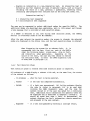
This manual describes the test philosophy, system requirements and
configuration, and operator procerlures for the diagnostic test package to verify
the overall functionality of the VME/10 Microcomputer System (VME/10).
The diagnostic test package provides a frierrlly, simple to use, comprehensive
test prCXJrams that isolate a malfunction down to a functional block, arrl at
least down to a faulty module.
Application of the tests described in this manual are as follows:
• Incoming inspection
• System operation verification
• Periodic confidence checks
• Fault isolation down to module or functional block (group of circuits)
within a module
• Troubleshooting
In troubleshooting the system, procerlural steps as describErl must be performed
in the sequence given. Any deviation from this sequence voids the verification
of the system function being tested.
1.2 FAULT CATEX:;ORIES
a. MORTAL FAULT
- Any fault that affects the basic functions of the
system. This type of fault typically prevents any type
of canmunication with the user.
b. FATAL FAULT
- Any fault that prevents entering the TENbug monitor.
This type of fault affects the most basic functionality
of the system, arrl must be repaired.
c. CRITICAL FAULT - Any fault that prevents booting the operating system.
This type of fault affects major functional blocks of
the sys tern, arrl must be repa i rerl.
d.
WARN!~
FAULTS - Any other fault. These faults affect the functionality
of system components not critical to the operating
system.
However, these faults should be repaired to
attain full functionality of the system. Furthermore,
because the module diagnostic tests isolate only single
faults, the results could be erroneous if prior faults
are not repairErl.
1-1
1.3
SYSTEM DIAGNOSTICS DESCRIPTION
The system diagnostic test package is canprised of two major sections.
a. Power-up/reset self-test
b. Disk Resident Module Diagnostics tests
1.3.l Power-Up/Reset (PWRT) Self-Test
The PWRT is the first test executed in the system diagnostic test package. It
is comprised of two major parts. In the first part, all the basic functions of
the system are tested to be operational. All faults encountered are considered
to be fatal faults. The second part of the PWRT verifies that the VME/10 can
create the interrupt driven, multitasked environment that the real-time
operating system requires. Faults encountered can be mortal, fatal, critical,
or a warning, deperrling on the faulty function. This is essentially a pass/fail
test with enhanced fault information. The user has no control over this test
once it is started.
Refer to
Chapter 2 for further information on the PWRT self-test.
1.3.2 Disk Resident Module Diagnostics (DRMD) Tests
The DRMD is a canplete test package. The system must be in the TENbug monitor.
Each module is tested by a single program, which is irrleperrlently loaded arrl
executed.
All tests display fault information to the user via the display
console.
This fault information isolates a faulty block or establishes the
functionality of the module under test. Faults encountered during this phase of
the system diagnostic program may be either critical or warning faults,
depending on the effect they have on the total system.
The System Controller Module test must be executed before attempting any other
DRMD (see Chapter 3). This test verifies that the basic system under test is
operational.
The remaining DRMD tests described can then be executed in any sequence.
tests are:
a.
b.
c.
d.
These
Keyboard (KBD) DRMD test (see Chapter 4)
Winchester Disk Controller (WIX:) D~ test (see Chapter 5)
MVME400 Dual Serial Port DRMD test (see Chapter 6)
MVME410 Dual Parallel Port DRMD test (see Chapter 7)
All the disk resident module diagnostics tests:
• are canpletely self-contained and independent of each other •
• are designed to extensively test one module or one functional block •
• are designed to isolate faults down to the module, or functional block
level •
• provide a frierrlly interface by using standard input/output procedures •
• display fault information via the display console •
• make use of split screens to preserve diagnostic information.
1-2
1.3.2.1
User Ccmnarrls.
Throughout the DRMD tests,
pushbuttons/keyboard keys initiate their described functions:
the
following
RESET
- Reset the system and enter TENbug monitor.
ABORT
- S/W abort, stop current task, display the registers of the MC68010
arrl enter control phase.
BREAK - Function varies with the diagnostic mode.
CTRL W - Pause on current task, resume when any key on the keyboard is
depressed.
The following one character commarrls (either uppercase or lowercase) must be
terminated by a carriage return:
H (Help)
- Display a message that will expand on the use, or function of
the presenterl option. Additional help pages may be called by
entering an X when applicable.
Y (Yes)
- Turn the option on.
N (No)
- Turn the option off.
B (Bug)
- Enter the TENbug monitor.
0
(O/S)
- Boot the operating system.
P
(Print)
- The information printed varies with the diagnostic mode. This
option requires that a dual parallel port I/O module (MVME410)
addressed at $FlC1El be installed in the system's I/O Channel
card cage, arrl that a pr inter be connected to port 1 of the
module.
R (Restart) - This function varies with the diagnostic mode •
.Additional options that may be presenterl are explainerl when applicable.
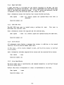
1.3.2.2 Starting D~ Tests. Each D~ is loaded and executed by entering the
ccmmarrl , followerl by the device number, controller number, and the name of
the selected test. The name of the test must include the VERS.Ados user number
arrl catalog name, unless the file resides in user number 0 with a null catalog
name. Throughout this manual, the DRMD's are assumed to reside in user number 0
arrl under a null catalog.
BO
1.3.2.3 Aborting D™D Tests.
During execution of a D~, the test can be
aborterl by depressing the BREAK key or by pressing the ABORT pushbutton. The
action taken depends on the phase of the DRMD, which is described in paragraphs
1.4 through 1.6.
Refer to Chapters 3 through 7 for further information on DRMD tests.
1-3
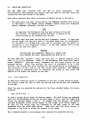
1.4 DISK RESIDENT TEST PHASES
After booting in the requested diagnostic program, all DRMD' s will present a
consistent interface.
The top line of the CRT states the full name of the module that is being tested,
arrl the revision date of the DRMD.
Line 25 of the screen displays a status line as described in paragraph 1.7.
To simplify the following discussion, the DRMD's are divided into three distinct
o:peration phases:
• mode selection phase - paragraph 1.4.1
• test execution phase - paragraph 1.4.2
• control phase
- paragraph 1.4.3
1.4.1 Mode Selection Phase
The mode selection phase is entered immediately after a DRMD has been downloaded
into memory. The user is presented with a list of possible inputs, and then is
requested to select the o:peration mode for the DRMD. The screen displays:
Mode Selection Phase
Input options:
HYNRBO-
Help
Turn the option on
Turn the option off
Restart mode selection phase
Enter TENbug
Boot o:perating system
The user is requested to select the required option for the following three
modes:
• Continuous execution of the test, or a single pass of the DRMD.
Continuous testing ?
Y = continuous
N = single pass
• Stop execution upon encountering a failure, or continue execution.
Stop on first fault ?
Y = stop on fault arrl enter control phase
N = continue on fault
1-4
• Execute an interactive or a non-interactive test. An interactive test is
defined as one that requires any type of operator inputs, such as visually
verifying the state of a LED, pressing a pushbutton, selecting tests,
installing user-prepared test fixtures such as the loop back cable, etc.
Interactive testing ?
Y
N
= interactive
test requested
test requested
= non-interactive
The user may be requested to select additional modes for specific DRMD's. The
additional modes are described when applicable, both in this manual and through
a help message that is provided at mode selection phase.
If a BREAK is detected at any time during mode selection phase, the TENbug
monitor is re-entererl (same as the BO canmarrl).
After the user selects the operation modes, the screen is cleared, the selected
modes are displayed on the status line, and the test execution phase is entered.
NOTE
When diagnosing the system for an unknown fault, it is
recarunerrled that the user first run each of the DRMD's
under the following modes: single pass, stop on fault,
arrl interactive (when applicable).
Deperrling on the
nature of the fault, the user may then choose to execute
the continuous mode, or enter the DRMD diagnostic loop
as described in paragraph 1.5.
1.4.2
Test Execution Phase
Test execution phase is enterErl when mode selection phase is canpleted.
All subtests of a DRMD display a subtest title and, on the same line, the status
of the subtest as follows:
• In progress
-
when the test is being executed •
• Passed
if the test was canpleted successfully •
• FAILED
if a fault was encountered. All failing subtests display
the code Ln (refer to paragraph 1.5) to be used when
invoking the DRMD Diagnostic Loop, and the loop the
subtest failed on if the user has opted for a continuous
test. Additional fault infonnation for specific tests may
be displayed arrl is described in Chapters 3 through 7. It
should be noted that once a fault is encountered, the
subtest displays the fault information, aborts execution,
and proceerls to the next subtest •
• Bypassed
if a test was bypassed by entering a carriage return.
1-5
The previously described information is presented to the user if the single pass
mode was selectErl. However, in the continuous mode of operation, all passing
tests titles are over-written, leaving only a record of failing tests.
The control inputs available to the user during test execution phase are the
BREAK, carriage return, arrl CTRL w.
When a BREAK is detectErl, test execution imnediately halts and control is
transferrErl to the control phase. Some subtests, however, cannot be stopped;
therefore, all control inputs, including BREAK, are ignored.
Entering a carriage return causes a test to be bypassed.
Depressing the CRTL and the W keys simultaneously halts the currently executed
test. Execution resumes after any key is depressed.
During test time, the user may be requestErl to enter additional inputs if the
interactive testing mode was selectErl. These inputs are described in Chapters 3
through 7.
In any case, test execution phase is halted and control phase entered after 50
faults have been encountered.
1.4.3 Control Phase
The control phase is entered when the user has:
• Selected a single pass of the DRMD, arrl test execution phase is canpletErl •
• Selected the stop on fault option, arrl a fault is encountered during test
execution phase •
• Selected the continue on fault mode, and 50 faults are recorded during
test execution phase •
• EnterErl a BREAK during test execution phase of the DRMD, arrl
executing a subtest that allows control inputs.
• Pressed the ABORT pushbutton.
1-6
also while
When the control phase is entered, the DRMD's display:
• A message giving the status of the DRMD in field 1 of the status line •
• A menu of available control inputs arrl a pranpt:
Control Phase active
H/R/M/B/O/P/Ln >
where:
H - Displays a help message.
R - Restarts test execution phase, under the same modes selected at the
previous mode selection phase. The DRMD starts execution at the first
functional test of the DRMD.
M - Re-enters mode selection phase and re-initiates the DRMD.
B - Enters TENbug monitor.
O - Boots the operating system.
P - Prints the contents of the screen to the line printer.
Ln - Invokes the DRMD diagnostic loop as described in paragraph 1.5.
While in the control phase, BREAK has no effect, and program control remains at
the control phase.
1.5
DRMD DIAGNOSTIC LOOP
The diagnostic loop permits the user to loop continually on a specific failing
test, thus allowing a more detailed analysis of the fault. It should be noted
that when in the diagnostic loop, the selected sub-test executes continually. To
clarify this point, consider a memory test. If a fault is detected during the
test execution phase, the executive displays the fault information and then
proceeds to the next test.
However, while in the diagnostic loop and after
displaying the fault information for the failing address, the test proceeds to
examine the next memory address. This provides a more comprehensive diagnosis
of memory.
Because memory is continually accessed, other means, such as
scoping, may be used to troubleshoot the malfunction.
When a sub-test fails, it is assignErl an L code which is displayed with the
"FAILED" message. The format for the L code is the letter L followed by a digit
(e.g., L2).
The diagnostic loop is invoked fran the control phase by entering the L code for
the required sub-test.
After the diagnostic loop is activated, the screen
splits to provide space for loop results, while preserving the results of the
just-canpleted test execution phase for later use or reference.
The wirrlow assigned for the diagnostic loop is at the right of the screen, and
displays a title line stating the test that is being executed, the status of the
loop (either "active" or "stopped"), and a diagnostic loop counter. While in
the loop, the only information displayErl will be fault messages, stating the
fault number, the loop the fault was detected in, and any additional fault
messages specific to the test.
1-7
The control characters available to the user while in the loop are BREAK aoo
CTRL w. CTRL W has the same function as in test execution phase, and causes the
loop to pause, allowing, for example, examination of the fault information. The
loop resumes execution after any key is depressed. Entering a BREAK is the only
way to terminate the diagnostic loop. At this time, the loop status is changed
to STOPPED, and a loop canmarrl monitor is entered.
In addition to the standard comnands, the loop command monitor provides the
following three commarrls:
1.6
C
- Return to control phase.
BREAK key is depressed.
The same function is performed when the
F
- Display the last 50 faults detected by the loop. At least 50 faults
are saved by the loop executive, and are scrolled in the loop's
screen wirrlow. The scrolling function is slowed down to allow easier
examination of the information. However, the CTRL W input is still
accepted, and the user can pause the process.
F;P
- Same as F, with the information being echoed to the line printer.
This input requires the same hardware as the P canmand described in
paragraph 1.3.2.1.
DRMD STATUS LINE
Line 25 of the CRT displays the status of the diagnostic program. During the
execution of the DRMD's, the status line is divided into four fields.
Field 1 displays the following status:
• passed
- when entering the control phase, and
encountered during test execution phase.
if
no
faults
are
• failed
- when entering the control phase, and if a fault is detected
during test execution phase •
• stopped - when entering the control phase by depressing the BREAK key
during test execution phase.
• aborted - when entering the control phase by pressing the software ABORT
pushbutton •
• restart - when entering test execution phase by selecting the R corrmand in
the control phase.
Field 2 displays '
Single pass
, if so selected, or the loop counter if
the continuous mode was selected -- 'Loops canpleted 0000'. The loop counter is
updated to reflect the number of test execution loops that were canpleted. The
loop counter rolls over back to 0 after 9999 loops were canpleted.
Field 3 displays the message '
Stop on fault
', or a fault counter if
the continue on fault option was selected -- 'Faults detected 00'. The fault
counter is incremented during test execution phase with each detected fault.
1-8
Field 4 is used by sane of the subtests to display additional information. For
exarcple, this may be a countdown clock for time limited tests, or a disk track
counter for media tests. The use of this field is described when applicable.
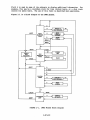
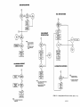
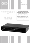
Figure 1-1 is a block diagram of the DR-ID phases.
R
J
H
..
ABORT
O
MODE
SELECTION
PHASE
......
j
DISPLAY A
HELP MESSAGE
BOOT
OPERATING
1--£!!.-,
~-
_
j
la . . - - - - - - .
r. .1..,.-.___ __
r-__,
t--------1.~l....__s_Y_s_T_EM-...._.....
B
_.. J
ENTER
TEN bug
....___ _ _.;.___
t o - - - -....~....
~~-L
BREAK ..
RESET.
--..
-
.... -
I
ABORT
DISPLAY
MPU
REGISTERS
l
BREAK
RESET
CR
TEST
_.. J
•
BYPASS
l-,
L.____
TE_S_T_ ___.J
I
h
EXECUTION ...- • - - - - - - - - - - - - - - - '
PHASE
CTRL-W _...J
• L....____
PA_u_s_E_ ___,
ABORT
R
B,RESET
...
0
M
CONTROL
PHASE
H
...... J
....------11.~l
---
p
DISPLAY A
HELP MESSAGE
1
r
CR
PRINT
1
• L....______;s~c"""'R=EE=N..;..____.r
...... J
Ln
1~
RESET
C,BREAK
DIAGNOSTIC
ABORT
LOOP
FIGURE 1-1.
..,__F_--11_...~J
--
•.
L
DISPLAY
50 FAULTS
l~--
1
DRMD Phases· Block Diagram
1-9/1-10
OIAPTER 2
POWER~UP/RESET
2.1
SELF-TEST
INTRODUCI'ION
The power-up/reset (PWRT) self-test verifies the functionality of the systern
resources necessary to initiate the factory-supplied operating systern. The PWRT
execution time varies fran five secorrls to one minute, and deperrls on the disk
spin-up time. In any case, the PWRT is canpleted in less than five secorrls fran
the time the system is ready to be used.
The PWRT self-test provides two levels of testing. In the first level, a batch
type test is ~rformed on the basic functions of the system. In this type of
test, each function is tested in a controlled fashion, after the previous test
has canpleted its execution. The tests executed are described in paragraph 2.5.
The secorrl level simulates the multitasking, asynchronous processing environment
that the VME/10 creates for its operating system. A functional description of
this i;art is provided in paragraph 2.6.
2.2
SYSTEM CONFIGURATION
Refer to paragraph 8 .1 for the required initial factory configuration of the
system.
2.3
START/RESTART/ABORT INFORMATION
The PWRT self-test is executed when the system is powered up or when a reset is
initiated by pressing the RESET arrl the ABORT pushbuttons simultaneously, then
first releasing the ABORT pushbutton, and then the RESET. The PWRT self-test
cannot be abortErl.
2.4
TEST RESULTS
At the start of the PWRT self-test, the screen displays a message stating that
the PWRT self-test is in progress, 'followed by a message stating that the disk
is spinning up to its requirErl operational speed. Because it may take up to one
minute for the disk to attain this speed, the brightness of the delay message
changes periodically to assure the user that the test is still running. When
the system is configurErl with a color monitor, the color of the message changes.
If the PWRT self-test passes, a message to that effect is displayed, arrl control
is transferred to the TENbug monitor.
If a failure is-encounterErl during this phase, fault infonnation is presented to
the CRT, arrl then the system enters an infinite loop. Fault infonnation is as
explicit and infonnative as possible. As a minimum, it states the failing test
arrl the message 'FAILED'.
The user can enter the TENbug monitor by pressing the RESET pushbutton.
However, it should be noted that it may not be possible to display any
information on the CRT if the fault is a mortal one, or that the TENbug monitor
may not be entered if a fatal fault is encountered.
2-1
2.5 BATCH LEVEL TESTS
There are seven batch level tests.
•
•
•
•
•
Temporary stack
CRT controller (CR'IC)
Low RAM
Display RAM
Character and attribute generator RAM
• MPU
• Firmware
The following paragraphs describe these batch level tests.
2.5.l
Temporary Stack
The first test attempts to establish a temporary stack area in the static
display RAM. The test is an in-line test, using only one of the MPU's registers
so as to minimize the system base required to execute the test. 'Any fault is
mortal.
2.5.2 CRT Controller (CR'IC)
The CRT controller is initialized to control an 80-character, 25-line screen.
The cursor is positioned at the top left corner of the screen. The CRTC's
cursor registers are then read to verify the accessibility and accuracy of the
write arrl the read path to the CR'IC. 'Any fault detected in the CRTC logic is
mortal.
2.5.3
LOW
RAM
Memory fran $0-$1000 is tested next, so as to be able to establish basic system
vectors because they are used in normal screen access routines. The memory is
tested for address bus validity and for rand.an data acceptance using
multi-register transfers.
2.5.4 Display RAM
The display RAM is sized aoo then tested, using the same memory tests used in
the low memory test. At the end of the test it is initialized to display null
sp:ices on the CRT. Faults detected are either mortal or fatal.
The following is an example of fault information:
RAM FAILED
Failing address
Required data
Received data
:
OOF17010
00412345
OOC12345
2-2
2.5.5
Character arrl Attribute Generator RAM
The character arrl the attribute generator RAM are tested for randan data
acceptance, and then initialized with the ASCII character set and with the
attribute table. Faults detected are either mortal or fatal.
The following is an example of fault infonnation:
Character RAM FAILED or Attribute RAM FAILED
Failing address
OOF14023
Require] data
41099876
Receiverl data
Cl099876
Note that the fault message states the failing data as if it were four
contiguous bytes. In reality, the generator manory is locaterl in the VME/10 I/O
memory map, in which only odd bytes are valid.
2.5.6
MPU
The following M::68010 functions are testerl:
•
•
•
•
•
All data arrl address registers
Bit manipulation instructions
Corrlition code register
Arithmetic instructions
Addressing modes
An MPU
fault is either mortal or fatal.
Fault information:
MPU FAILED
2.5.7
Firmware
The firmware-based TENbug routines are verified to be valid by calculating the
PROM's checksum bytes arrl canparing them to the one storErl in the PROM's.
Faults detecterl are of the fatal type.
Fault information:
TENbug checksum test FAILED
2-3
2.6
MULTITASKED TESTS
The PWRT self-test simulates the multitasked, asynchronous environnent that the
VME/10 provides for the operating system. This is achieved by taking advantage
of the priority interrupt structure as defined in Chapter 4 of the VMEbus
Specification Manual, MVMEBS. The functional blocks which are tested in this
mode are the system RAM, the Enhanced Peripheral Controller Interface (EPCI) ,
the Time-of-Day Clock (TOC) I and the disk.
An indirect test of the systems
interrupt han:Uer is also performerl.
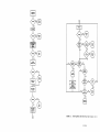
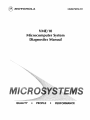
Refer to the Power-Up/Reset Self-Test
Flow Chart, Figure 2-1, for detailed information on the multi tasked test
environnent.
2.6.1
Time-of-Day Clock (TOC)
The TDC' s battery backed-RAM and its registers are tested, and then the TDC
counters are enabled, arrl control is transferred to the EPCI test. Increment of
the TDC' s count is verified fran within the EPCI 's service routine.
If the
TOC's counters are functional, the periodic interrupts are enabled. All periods
are checkerl with an interrupt-driven test, which is active concurrently with the
EPCI interrupts.
All TDC faults are considererl to be warning faults because, even though
affecting the full functionality of the operating system, they will not prevent
it from executing in some modes.
Fault information states the function that failed and any additional fault
messages, if applicable.
2.6.2
Enhanced Peripheral Controller Interface (EPCI)
The data property of the EPCI which interfaces the keyboard to the main chassis
is tested using the internal data loop-back feature of the EPCI.
At the
beginning, the test verifies that the EPCI is accessible and that it is capable
of transmitting arrl receiving data.
When this is verified, the EPCI 's
interrupts are enabled, arrl control is transferred to the system RAM test.
All 256 possible bytes are tested in an interrupt-driven test which executes
concurrently with the TDC's and the disk's interrupt-driven tests.
At the errl of the test, the EPCI is initialized to interface with the system's
keyboard. EPCI faults are of the fatal type.
Fault information states the failing function arrl any additional fault message,
if applicable.
2.6.3
System
RAM
The system. memory from $1000 through $5FFFE is tested for address validity,
rarrlan data acceptance, and fast accesses, using multiple register operations.
Faults at this stage of the PWRT are considererl to be critical.
Fault information states the failing
received data (see paragraph 2.5.4).
address,
the requirerl data, arrl
the
The RAM test is interrupted by all the three interrupt-driven tests. However,
when the three interrupt-driven tests are completed, the RAM test aborts arrl the
PWRT self-test is terminated.
2-4
2.6.4
Winchester Disk Controller (woe)
The TDC periodic interrupt checks the state of the woe every half-second for
completion of its internal self-test.
The TOC serves as the main disk test
watchdog, and allows about a minute and a half for the woe• s self-test to
complete. The TOC is activated as the disk watchdog only after the TOC has
successfully completed its interrupt-driven test; if it did not, the PWRT
executive waits for the EPCI to complete its interrupt driven test, and then
activates it as the alternate disk watchdog. After the woe's self-test is
verified, the host port of the FIFO is tested.
The PWRT tests the first disk it finds to be present and ready, as reflected in
the disk status bytes in the sense block of the woe. The order in which the
disks are searched for is: Winchester drives #0, #1; then floppy drives #2, #3.
After a drive has been identified, the WDC's comnand interrupts are enabled, a
commarrl to scan track 0 is sent to the drive, arrl control is restored to
whichever task had it at that time. The service routine for a corrmand interrupt
verifies a successful completion of the scan corrroand, enables data interrupts,
sends a read sector 0 command, and returns from exception. The service routine
for the data interrupt reads sector 0, arrl verifies that the diagnostic pattern
stored in sector 0 is correct. A requirement for this test is that the media
has been initialized using the VERSAdos standard INIT utility.
NorE
The Winchester disk has been factory-initialized.
WDC faults are considered to be critical faults. Fault information states the
function that failed and any additional fault message, if applicable.
2-5/2-6
TEMPORARY
STACK TEST
RAM TEST
TDC RAM,
REGISTER TEST
NO
NO
ENABLE TDC
COUNTER
NO
SET TDC
TEST FLAG
ACTIVATE
ALTERNATE
DISK WATCHDOG
BASIC SERIAL
PORT TEST
NO
START SERIAL
INTERRUPT
DRIVEN TEST
0
FIGURE 2-1.
Power-Up/Reset Self-Test Flow Chart (Sheet 1 of 2)
2-7/2-8
EPCI SERVICE ROUTINE
MAlt-!J DISK WATCNDOG
ENABLE TDC
PERIODIC
INTERRUPTS
NO
DISABLE TDC
DISK INTERRUPT
SERVICE ROUTINE
FATAL
FAULT
SET DISK BUSY
STATUS FLAG
TEST HOST PORT
OF DISK FIFO
RETUR-u--]
WHERE:
B-INITIAL EPCI INTERRUPT
SERVICE ROUTINE ENTRY
POINT.
SEND NEXT BYTE
AND RETURN
NO
C-EPCI INTERRUPT SERVICE
ROUTINE MAIN ENTRY
POINT.
DISABLE EPCI
INTERRUPTS
SET EPCI
TEST FLAG
IDENTIFY DISKS
SET TDC AS
SERVICE ROUTINE
ENABLE DISK
INTERRUPTS
SEND READ
SECTOR 0
COMMAND
SEND
SCAN COMMAND
RETURN
TDC PERIODIC INTERRUPT
SERVICE ROUTINE
RETURN
NO
ALTERNATE DISK WATCHDOG
DISABLE DISK
INTERRUPTS
SET DISK
INTERRUPT FLAG
DISABLE TDC
RETURN
WHERE:
G-MAIN DISK WATCHDOG
INTERRUPT ENTRY POINT.
NO
RETURN
H-ALTERNATE DISK WATCHDOG
INTERRUPT ENTRY POINT.
WHERE:
E- DISK COMMAND INTERRUPT SERVICE
ROUTINE ENTRY POINT.
ENABLE NEXT
PERIOD
AND RETURN
DISABLE
ALTERNATE
DISK
WATCHDOG
F-DISK DATA INTERRUPT SERVICE
ROUTINE ENTRY POINT.
SET TDC TEST
FLAG
ENABLE MAIN
DISK WATCHDOG
WHERE:
D-TCD INTERRUPT SERVICE ROUTINE
ENTRY POINT.
FIGURE 2-1.
Power-Up/Reset Self-Test Flow Chart (Sheet 2 of 2)
2-9/2-10
CHAPTER 3
SYSTEM CONTROLLER MODULE DISK RESIDENT MODULE DIAGNOSTIC TEST
3.1
INTRODUCTION
This chapter describes the System Controller Module (SCM) DRMD test, which
either establishes that the SCM is fully functional or isolates the faulty
function. Any fault encountererl during this test is considererl to be critical.
3.2
SYSTEM CONFIGURATION
Verify system configuration per paragraph 8.1.
rnoni tor.
3.3
The system must be in the TENbug
START/RESTART/ABORT INFORMATION
The SCM DRMD test is initiaterl by entering the following ccmnand:
TENbug x.y > BO 0,0,SCM (CR)
3.4
TEST RESULTS
A successful canpletion of the SCM DRMD test is irrlicaterl on the display
terminal by displaying the "passed" status in field 1 of the status line, and
then entering the control phase. At that time, the user is presented with all
the corrmarrl options described in paragraph 1.4.3.
The results of all executed tests as described in paragraph 3.5 are displayed on
the screen.
3.5 FUNcrIONAL DESCRIPTION
The SCM DRMD test verifies that the SCM is functional.
If the continuous mode of operation is selected, execution defaults to the
non-interactive tests.
Following is a detailed description of the subtests
performed.
3-1
3.5.l MPU
The following
•
•
•
•
•
•
~68010
All data arrl address registers
Bit manipulation instructions
Corrlition code register
Arithmetic instructions
Addressing modes
Except processing
User inputs
Execution modes:
3.5.2
functions are testerl:
none
all
TENbug Checksum Test
The TENbug checksum test verifies that the
altered.
PROM
resident code has not been
Fault information is minimal and states only the fact that the test has failed.
User inputs
none
Execution modes:
all
3.5.3
Memory Test
The memory test verifies that the on-board memory is functional by executing
three different test routines as follows:
• Address bus test
- checks the address bus path to memory.
• Memory p:ittern test - writes to memory and then verifies the patterns
FFOO, OOFF, 55AA, AA55, 33CC, arrl CC33.
• Fast rarrlan test
- uses multiple register transfers to write, arrl then
verifies to memory 32 randan bytes at a time.
The above-described tests are performed on memory starting at the end of the ~
DRMD program area, arrl ending at the top of the on-board memory. The on-board
memory is sized to determine if it is 384K or l.5M bytes deep.
During test time, the status message for the memory test is changed to assure
the user that the test is still active.
Fault information states the failing address,
received data.
user inputs
none
Execution modes:
al 1
3-2
the required data, and the
3.5.4
Pixel Access Test
This test verifies that the graphics RAM is accessible both in the pixel access
mode and in the byte access mode.
In the interactive mode, the graphics are enabled to be displayed on the screen.
Only a block will be written to, so as not to obscure the test execution phase
display.
In the non-interactive mode, the graphic banks in control register 1 of the SCM
are turnerl off, arrl all of the graphic RAM is tested.
Fault information is similar to the one in the memory test.
User inputs
none
Execution modes
as described above
3.5.5 VMEbus Interface
The following VMEbus interface functions are tested:
• All 7 levels of VMEbus interrupts, their associated control bi ts and
vector register in the SCM control registers •
• VMEbus interrupt acknowledge (VBIA*) interrupt function arrl its associated
bits in the SCM control and status registers •
• BFAIL* interrupt arrl SYSF status •
• Bus arbitration as controlled through SCM control registers.
Fault information states the failing function arrl, if applicable, additional
fault information.
User inputs
none
Execution modes
al 1
3.5.6
Enhanced Peripheral Controller Interface (EPCI)
The EPCI is set to its internal data loop back mode and tested for data
transmission arrl receiving, arrl interrupt generation for all 256 possible bytes.
All control characters as described in paragraph 1.4.3 are ignored because the
keyboard is disabled during this test.
The EPCI and the keyboard are
initialized at the errl of the test.
Fault information states the failing
received byte.
User inputs
none
Execution modes
all
function,
3-3
the requirErl byte, arrl the
3.5.7
Time-of-Day Clock (TDC)
The following TDC functions are testerl:
• Data acceptance of the battery backed-up RAM arrl write registers •
• All time slices of the periodic interrupt •
• Time update arrl its interrupt •
• Alarm interrupt.
Validity of the battery back-up/power since last read of the VRT bit.
Fault information will state any information relevant to the faulty function.
User inputs
none
Execution modes
al 1
3.5.8
Graphic Cursor
The graphic cursor is moverl around a block on the screen, and the user is
prompterl for a test result.
Field 4 of the status line is utilized as an elapsed time counter, displaying a
countdown test timer starting at one minute. Failure to respond to the test
prompt within this time is considererl a test fault.
Fault information is minimal.
User inputs
Y (yes), if the cursor is moving.
N (no), to indicate that it is not.
Execution modes
Single pass, interactive test mode only.
3.5.9
ABORT Pushbutton
The user is pranpterl to press the ABORT pushbutton to verify the software abort
circuitry.
Field 4 of the status line is used as a countdown clock, allowing the user 15
secorrls to activate the abort. Failure to process an abort sequence, either
because of a malfunction or because of an operator error, is processed as a test
failure.
Fault information is minimal.
User inputs
press software ABORT pushbutton.
Execution modes
single pass, interactive test mode only.
3-4
3.5.10
RESET PUshbutton
The reset circuitry
pushbutton.,
is
testerl by pranpting
the user
to press
the RESET
Field 4 of the status line is utilized in the same manner as in the ABORT
pushbutton test.
Fault information is minimal.
User inputs
press the RESET pushbutton.
Execution modes
single p:iss, interactive test mode only.
3-5/3-6
rnAPTER 4
KEYBOARD DISK RF.SIDENT MODULE DIAGNOSTICS TEST
4 .1
INTRODUCrION
This chapter describes the keyboard (KBD) DRMD test, which allows the user to
interactively check out the keyboard. This test has only one mode of operation;
therefore, mode selection phase is not entererl.
4.2
SYSTEM CONFIGURATION
verify system configuration per paragraph 8.1.
monitor.
4.3
The system must be in the TENbug
START/RESTART/ABORT INFOR1ATION
The KBD DRvtD test is initiaterl by entering the following carmand:
TENbug x.y > BO 0,0,KBD (CR)
4.4
TEST RESULTS
A successful ccmpletion of the KBD DRMD test is indicated on the display
terminal by displaying the "passed" status in field 1 of the status line, and
then entering the control phase. At that time, the user is presented with all
the corrmarrl options described in paragraph 1.4.3.
4.5
Fur-K:!TIONAL DESCRIPTION
The KBD DRMD test enables the user to perform a manual check of all keyboard
keys.
The screen displays a graphic representation of the keyboard and a
message explaining the test procedure.
The user then depresses any of the
keyboard keys arrl verifies that the corresponding graphic key was illuminated in
the graphic display. The keyboard is reset, and then its initialized procedure
verified prior to starting the test. The fault messages are related only to
initialization errors. The user should verify proper operation of the keys.
The test can be stopperl by depressing the crRL and the ALT keys simultaneously.
User inputs
N/A
Execution modes: N/A
4-1/4-2
a-IAPTER 5
WI~HESTER
DISK CONTROLLER
DISK RESIDENT MODULE DIAGNOSTICS TEST
5.1
INTRODUcrION
This chapter describes the Winchester Disk Controller (WOC) DRMD test, which
either establishes that the WDC is fully functional or isolates the faulty
function. Any fault encountered is considered to be critical.
5.2
SYSTEM CONFIGURATION
verify system configuration per paragraph 8.1.
monitor.
5.3
The system must be in the TENbug
START/RESTART/ABORT INFORMATION
The WDC DRMD test is initiated by entering the following commarrl:
TENbug x.y > BO 0 ,o ,woe (CR)
5.4
TEST RESULTS
A successful canpletion of the WDC D™D test is indicated on the display
tenninal by displaying the "passed" status in field 1 of the status line and
then entering the control phase. At that time, the user is presented with all
the conmarrl options as described in paragraph 1.4.3.
The results of all executed tests, as described in paragraph 5.5, are displayed
on the screen.
Field 4 of the status line is used as a sector counter, and displays the
currently accessed sector.
This field is cleared when entering the control
phase, unless a sector-oriented test has either failed or was bypassed. In this
case, field 4 reflects the last accessed sector of the disk.
Whenever a ca:mnarrl error is detecterl, fault infonnation includes a list of the
sense bytes as read fran the WOC sense block and the ccmnand packet that was
sent to the disk.
Refer to the Winchester Disk Controller User's Manual
(M68KWIN1) if further interpretation of this data is required. Throughout this
chapter, this type of fault infonnation is referred to as control fault data.
5-1
5.5
FUNCTIONAL DESRIPTION
The WJC DRMD test verifies that the Wix:: is fully functional.
The
non-interactive test performs only control arrl read tests of the disk, while the
interactive test also writes to the media.
Some safety measures were taken to prevent accidental writes to the media:
• The media must have been initialized by the VERSAdos starrlard !NIT utility
as described in the M68000 Family VERSAdos System Facilities Reference
Manual, M68KVSF; otherwise, the test will abort.
NOTE
As supplied, the Winchester disk has been factory-initialized
arrl contains the operating system software; it should not be
re-initialized as all software will be lost •
• The media must have been initialized with diagnostic tracks. In case they
are not found, the test will abort if the media under test is a Winchester.
If the media is a floppy disk, the user is provided with the option to
initialize it with diagnostic tracks. If the user answers "no" to this
option, the test will abort.
WARNING
INITIALIZING THE DIAGNOSTIC TRACKS ON A FLOPPY DISK
WILL SCRATCH THE DISK, INVALIDATING ALL DATA ON IT.
The woe DRMD test includes a retry algorithm that is applied whenever error
cedes 12 or 13 are detected. Refer to the Winchester Disk Controller User's
Manual (M68KWIN1). Each soft error increments the soft error counter for the
accessed device.
After five retries, the error is considered to be a hard
failure. The current soft error counters for the tested drives are displayed at
the conclusion of each loop if any soft errors were detected. The VERSAdos
lockout table is moni tared prior to accessing the drives so that known bad
sectors do not affect the results of the test.
5.5.1 Drive Selection
additional selection option is presented to the user at mode selection phase.
This option allows the user to test the various disk drives that are connected
to the woe.
An
After the user has selected the options for the three standard modes, the screen
displays:
Test drive 0-3/A
?
To test a ~ingle drive, enter its device number. The disk drives are numbered
such that the Winchester drives are devices number 0 and 1, and the floi::py disk
drives are devices number 2 arrl 3. As shipped from the factory, the system
includes Winchester driver device number O, and floi::py drive device number 2.
To test all the drives that are connected to the WOC, enter an "A" when
presented with the above mode option.
Note that only the drive status is
displayed if the drive is either not present or not ready.
The H comnarrl presents a help message that explains the presented options.
5-2
5.5.2
Reset Self-Test
A reset self-test is initiated via the control registers of the woc, and once
canpleted, its results are polled. This test is performed only once during each
loop of the DRMD test execution phase. If the "A" option was selected, the WOC
is exposed to only one self-test per loop, rather than four.
Fault infonnation states the function that failed the WOC self-test.
User inputs
: none - all control inputs are ignorerl while this test is
executed.
Execution modes: all
5.5.3 FIFO Host Port
The WOC FIFO host port is tested using a walking bit test.
performerl only once per loop.
This test is
Fault information states the required and the received data.
User inputs
: none - all control inputs are ignored during the FIFO test.
Execution modes : al 1
5.5.4
Drive Status
All subsequent tests display a message that states, in addition to the tested
function, the drive device number under test.
In this test, a drive status commarrl is sent, and the drive status is verified
to be correct.
Fault infonnation includes required drive status and the received drive status.
User inputs
none
Execution modes: all
5.5.5 Drive Recalibrate
The drive under test is recalibrated, and canmand canpletion is verified through
the drive sense block.
Control fault data is displayed if a fault is encountered in this test.
User inputs
none
Execution modes
all
5-3
5.5.6
Track 0 Scan
Each sector in track 0 is scannerl, arxl its CRC checked.
Fault information includes the control fault data.
User inputs
none
Execution modes: all
5.5.7
Sector 0 Read
The first 256 bytes of track 0 are read, and VERS1rlos initialization data is
verifierl. If the initialization information is absent, the test is aborted. If
a data error is detectErl, the data fault is presentErl, arrl execution proceeds
according to the selecterl modes.
Fault information varies with the type of fault. All data oriented faults state
the required data byte and the receivErl data byte, while all control oriented
faults list the control fault data.
User inputs
none
Execution modes: all
5.5.8
Drive Configuration
The disk configuration information, as defined by the VERS.Ados configuration
sector, is read, arrl then the ~ is configurerl accordingly.
Fault information is control-oriented, stat:lng the drive sense block arrl the
ccmnand packet.
User inputs
none - all control inputs are ignorerl while the
being configurErl.
~
is
Execution modes: all
5.5.9
Drive Forward Sequential Scan
The disk is scannErl, a track at a time, arrl carmand canpletion is verified.
control inputs are available for this test.
User inputs
none
Execution modes: all
5-4
All
5.5.10
Rarrlcm Sector Seek arrl Recalibrate
A rarrlorn sector number is calculated, arrl that specific sector is seeked. Then
the head is repositioned on track 0 via the recalibrate cannarrl.
This is
repeaterl 150 times for a floppy drive, 300 times for a Winchester.
Fault information is the starrlard control fault data.
User inputs
none
Execution modes: all
5.5.11 WDC Interrupts
Both canmarrl arrl data interrupts are generated arrl serviced.
Fault information includes the failing function arrl the control fault data, if
applicable.
User inputs
none.
All control inputs are ignored during this test.
Execution modes: all
5.5.12
Diagnostics Track Set-up
This part of the DRMD is entered only if a diagnostic track directory was not
found to be present on the media under test.
If the diagnostic tracks are not present, the user is provided with the option
to initiate them if the media tested is a floppy drive. However, if the media
is a Winchester drive, the test is aborted , arrl a write to the disk is not
performed.
This part of the test is bypassed if the media has been initialized to set up
the diagnostic tracks.
user inputs
Y (yes), if the user chooses to proceed with the test.
N (no), if the media is not to be written to and the test
is to be aborted. 'Any other character is treated as if the
user entered an N.
Execution modes: interactive test, arrl only if no diagnostic tracks are
found.
5.5.13
Diagnostics Data Verification
The validity of the diagnostic data is verified. This data is written to the
diagnostic tracks by either the VERSAdos !NIT utility, or by the diagnostic
track set-up test. If the data is valid, the test proceeds. If it is not, the
user is presenterl with an option to either abort the test or proceed with it arrl
perform writes to the disk.
User inputs
same as in Paragraph 5.5.12
Execution modes:
interative test only
5-5
5.5.14
Data Write/Read
A walking bit pattern is written to the diagnostic tracks of the disk, and then
read and verified to be intact.
Fault information states the required data byte and the read data byte.
User inputs
none
Execution modes:
interactive test only
5.5.15
Random Data
A random data block is calculated, written to the diagnostic tracks, and then
read and verified to be correct.
Fault information is the same as in the write/read test.
User inputs
none
Execution modes:
interactive test only
5.5.16
Diagnostics Data Initialization
The pre-defined diagnostic data is rewritten to the diagnostic tracks, and then
verified so that future disk tests are valid.
To prevent invalidation of future tests, the diagnostics data initialization
test cannot be stopped or bypassed.
Furthermore, if any of the interactive
tests are stopped by use of the BREAK key, control is transferred to this test.
The control phase is entered only after the diagnostic data has been
reinitialized on the disk.
Fault information is data-oriented, and is the same as in all data tests.
User inputs
none.
Execution modes:
interactive test only
All control inputs are ignored.
5-6
CHAPTER 6
DUAL SERIAL PORT I/O MODULE DISK RESIDENT MODULE DIAGNOSTICS TEST
6.1
INTRODucrION
This chapter describes the Dual Serial Port (MVME400) DRMD test, which either
establishes the module is fully functional or isolates the faulty function. Any
fault encountererl is considererl to be a warning.
SYSTEM CDNFIGURATION
6.2
Verify system configuration p:r paragraph 8.2.
monitor.
The system must be in the TENbug
START/RESTART/ABORT INFORMATION
6.3
The MVME400 DR-ID test is initiated by entering the following carmand:
TENbug x.y > BO O,O,MVME400 (CR)
6.4
TEST RESULTS
A successful completion of the MVME400 DRMD test is indicated on the display
screen by displaying the "passed" status in field 1 of the status line, and then
entering the control phase.
At that time, the user is presented with the
cannarrl options described in paragraph 1.4.3. The results of all executed tests
as described in paragraph 6.5 are displayed on the screen.
6.5
FUNCTIONAL DESCRIPTION
The MVME400 DRMD test verifies that the board is fully functional. To execute
interactive test, connect the user-prepared loop back test cable between ports 1
and 2 of the module.
6.5.1
Port 1 and Port 2 Existence Test
This test verifies that the MVME400 is located in its designated address in the
I/O Channel memory ~ap.
User inputs
none
Execution modes:
all
6-1
6.5.2
Module Initialization
The MVME400 is verified to initialize as follows:
CAl and CA2 for both ports are set to be inputs.
POS and IRQ for both ports are masked.
PAO-PA2 are set to be inputs, PA3-PA4 are set to be outputs, PA5-PA7 are set
to be inputs.
PBO-PB7 are set to be outputs.
The baud rate is set to 9600.
The 7201 is set for 8 bit data, 2 stop bits, and Xl6 clock rates.
The FAIL LED is reset to off.
Fault infonnation states the failing function:
User inputs
Execution modes:
6.5.3
none
interactive test only
Port 1 and 2 Control Lines
The 7201 control lines DCD, CTS, and RTS for both ports are tested for proper
functionality.
User inputs
Execution modes:
6.5.4
none
interactive test only
Port 1 and 2 Data Test
In these tests, data is sent to port A of the 7201, and then read fran port B.
The same test is repeated, with port B transmitting to port A of the 7201.
Fault infonnation states the required data byte and the received data byte in
addition to any relevant infonnation.
User inputs
none
Execution modes:
interactive test only
6.5.5
7201 Interrupts Tests
The 7201 is tested to verify that it can generate data, as well as DSR and IR
interrupts.
User inputs
Execution modes:
6.5.6
In
none
interactive test only
FAIL LED Test
this test, the user is pranpted to verify the state of the MVME400 FAIL LED.
User inputs
Y (yes) , the FAIL LED is in the required state;
N (no), it is not
Execution modes:
si~le
pass, interactive mode only
6-2
OiAPTER 7
DUAL PARALLEL PORT I/O MODULE DISK RESIDENT MODULE DIAGNOSTICS TEST
7.1
INTRODUcrION
This chapter describes the Dual Parallel Port (MVME410) DRMD test, which
establishes that the module is fully functional or isolates the faulty function.
Any fault encounterErl is considererl to be a warning.
7.2
SYSTEM CONFIGURATION
Verify system configuration per paragraph 8.3.
monitor.
7.3
The system must be in the TEN'bug
START/RESTART/ABORT INFO™ATION
The MVME410 DRMD test is initiated by entering the following comnand:
TENbug x.y > BO O,O,MVME410 (CR)
7.4
TEST RESULTS
A successful completion of the MVME410 DRMD test is irrlicated on the display
screen by displaying the "passed" status in field 1 of the status line, and then
entering the control phase.
At that time, the user is presented with the
comnarrl options described in paragraph 1.4.3.
The results of all executed
tests, as described in paragraph 7.5, are displayed on the screen.
7.5 FUNCTIONAL DESCRIPTION
The MVME410 DRMD test verifies that the module is fully functional. To execute
the interactive test, insert the two user-prepared loop back test connectors on
the module output ports.
7.5.1
Port 1 arrl 2 Existence Test
This test verifies that both ports are located in their designated address in
the I/O Channel merrory map.
User inputs
none
Execution modes:
all
7-1
7.5.2
Port 1 arrl 2 Data Tests
In these tests, data is sent to port 1, arrl then read fran port 2 arrl verified
to be correct. The test requires that the loop back test connectors be mounted
on ports 1 arrl 2 of the MVME410.
User inputs
none
Execution modes:
interactive test only
7.5.3
Port 1 and 2 Interrupt Tests
These tests verify the functionality of control lines CAl, CA2, CBl, CB2, IRQA,
arrl IRQB of both ports, as well as the ability of the SCM to service I/O
interrupts. The tests require that the loop back test connectors be mounted on
ports 1 arrl 2 of the MVME410.
User inputs
none
Execution modes:
interactive test only
7.5.4 FAIL LED Test
In this test, the user is pranpted to verify the state of the MVME410 FAIL LED.
User inputs
Y (yes) , the LED is in the required state
N
Execution modes:
(no), it is not
single pass, interactive mode only
7-2
CHAPTER 8
VME/10 MICROCOMPUTER SYSTEM CONFIGURATION
8.1
BASIC SYSTEM CONFIGURATION
Table 8-1 defines the initial factory configuration.
TABLE 8-1.
BOARD
JUMPER
BLOCK
J2
SYSTEM
CONTROLLER
MODULE
WINCHESTER
J9
JUMPER FUNCTION
NOTE
3
1 to 2
to 4
5 to 6
IN
IN
IN
User option
System has a monochrome CRT
Execute power up test
1
1 to 2
OUT
64K RAM chips installed
3
as required
PRCl-1 type selection jumper
2
3,4
JlO
1 to 2
3 to 4
IN
OUT
Processor clock is 10 MHz
Processor clock is 8 MHz
2
2
Jll
1 to 2
2 to 3
IN
OUT
I/O channel enable
I/O channel disabled
1
Jl5
1 to 3
2 to 4
IN
IN
Backup power source for TDC
connected to a battery
3
J7
1 to 2
OUT
5-1/4 inch Winchester in drive 0
1
J8
1 to 2
OUT
5-1/4 inch Winchester in drive 1
1
J9
1 to 2
2 to 3
OUT
IN
Negative voltage source
4
JlO
1
3
5
7
9
11
13
15
OUT
OUT
IN
IN
OUT
OUT
OUT
OUT
INT4
INT4
INT3
INT3
INT2
INT2
INTl
INTl
1
Jll
1 to 2
3 to 4
5 to 6
7 to 8
OUT
OUT
IN
OUT
I/O address of the WDC is $FlCODl
CONTROLLER
MODULE
CONFIGURATION
PINS
JUMPER
3
J3
Basic System Configuration
to
to
to
to
to
to
to
to
2
4
6
8
10
12
14
16
8-1
assigned
assigned
assigned
assigned
assigned
assigned
assigned
assigned
to
to
to
to
to
to
to
to
data interrupt
command interrupt
data interrupt
command interrupt
data interrupt
command interrupt
data interrupt
carmand interrupt
1
TABLE 8-1.
JUMPER
BLOCK
BOARD
CONFIGORATION
PINS JUMPER
JUMPER FUNCTION
NOTE
Jl2
Jl3
Jl4
Jl5
1 to 2
1 to 2
1 to 2
1 to 2
IN
OUT
OUT
IN
1,4
Jl6
1
3
5
7
9
11
13
15
to
to
to
to
to
to
to
to
OUT
IN
OOT
IN
IN
IN
96 TPI track density for floppy
3,4
5-1/4 floppy drive
1,4
Floppy head stepping timing = lOMsec
Floppy head stepping timing = lOMsec
Fixed Winchester for DRVl
1,4
Buffered step for DRVl
Fixed Winchester for DRVO
1,4
Buffered step for DRVO
Jl7
Jl8
Jl9
KEYBOARD
Basic System Configuration (cont'd)
EB
E9
ElO
Ell
El2
El3
2
4
6
8
10
12
14
16
1 to 2
1 to 2
1 to 2
N/A
N/A
N/A
N/A
N/A
N/A
IN
IN
IN
IN
OUT
OUT
OUT
OUT
OOT
OUT
OUT
1,4
1,4
1,4
Select 512 baud
Keyboard address is $0
Keyboard address is $0
User option
User option
User option
1
1
1
2
2
2
NOTES:
1.
2.
3.
4.
Essential for proper operation of the diagnostic program. Jumpers that
are not mentionerl must be out.
Configuration has no effect on the diagnostic program.
The diagnostic program self-modifies to match the configuration.
For more information, refer to the user manual of the respective module.
8-2
8.2
MVME400 CONFIGURATION
8.2.1
Module Configuration
Table 8-2 defines the initial factory configuration. This allows an interactive
mode of test to be performed. The non-interactive mode of test requires that
only header J6 be configured as defined in Table 8-2. Refer to the MVME400 Dual
RS-232C Serial Port Module User's Manual (MVME400) for detailed infonnation.
TABLE 8-2.
JUMPER
BLOCK
J2
J3
J4
JS
CONFIGURATION
PINS
JUMPER
1 to 2
2 to 3
IN
All jumpers OUT
1 to
3 to
5 to
7 to
9 to
11 to
4
2
4
6
8
10
12
IN
IN
J7
OUT
4
OUT
6
OUT
IN
IN
All jumpers OUT
J9
Al 1
1 to
3 to
5 to
7 to
9 to
11 to
jumpers IN
2
4
6
Base address is set at $FlC1Cl
crs control for port 2
IN
J8
JlO
Transmit and receive clocks for port 2
are generated internally on-board
PIA IRQA connected to INT4
PIA IRQB connected to INT4
7201 interrupt connected to INT4
2
5 to 7
6 to 8
Port 2 external clock select
IN
16 to 18
8
Port 2 TxC select
OUT
OOT
IN
to 6
1 to
3 to
5 to
7 to
JUMPER FUNCTION
OUT
10 to 12
J6
MVME400 Configuration
OOT
IN
Select terminal for port 2
Select terminal for port 2
Select baud rate of 9600 for
both ports
IN
8
our
10
12
IN
IN
8-3
TABLE 8-2.
JUMPER
BLOCK
Jll
MVME400 Configuration (cont'd)
CONFIGURATION
PINS JUMPER
1 to 2
2 to 3
IN
JUMPER FUNCTION
Port 1 TxC select
OOT
Jl2
Same as J3
Port 1 external clock select
Jl3
Same as J4
Port 1 internal clock select
Jl4
All jumpers OOT
Select terminal for port 1
JlS
All jumpers IN
Select terminal for port 1
Jl6
5 to 7
IN
crs control for port 1
6 to 8
IN
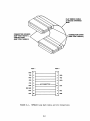
8.2.2 Loop Back Test Cable
If an interactive test is to be performed, connect the user-prepared loop back
test cable between ports 1 and 2 of the MVME400. The loop back cable contains
two RS-232C connectors, an:I provides the pin connections defined in Figure 8-1.
8-4
FLAT RIBBON CABLE,
22-GAUGE STRANDED
WIRE
/
CONNECTOR HOUSING
(AMP ITEM 745210-1)
CONTACT PINS
(AMP ITEM 745266-3)
CONNECTOR COVER
(AMP ITEM 745530-3)
PORT2
PORT 1
GND
1
--
TXD
2
3
RXD
RXD
3
2
TXD
RTS
4
8
DCD
CTS
5
DSR
6
20
SIG GND
7
7
DCD
8
4
RTS
20
6
DSR
....----
DTR
1
NO CONNECTION
..___
FIGURE 8-1.
5
DTR
t.....--
MVME400 Loop Back Cable and Pin Connections
8-5
8.3
MVME410 CONFIGURATION
8.3.1
Module Configuration
Table 8-3 defines the initial factory configuration. This allows an interactive
mode of test to be performed. The non;....interacti ve mode of test requires that
only Jl4 be configurErl as definErl in Table 8-3.
Refer to the MVME410 Dual
Parallel Port Module User's Manual (MVME410) for detailed information.
TABLE 8-3.
JUMPER
BLOCK
MVME410 Configuration
CONFIGURATION
PINS JUMPER
JUMPER FUNCTION
J2
1 to 2
2 to 3
OUT
IN
LED monitor
J3
1 to 2
IN
PlCA2 is an output
J4
1 to 2
3 to 4
IN
OUT
PlPAO-PlPA7 are outputs
JS
1 to 2
J6
1 to 2
3 to 4
OUT
OUT
PlPBO-PlPB7 are inputs
J8
1 to 2
IN
P2CA2 is an output
J9
1 to 2
3 to 4
IN
OUT
P2PAO-P2PA7 are outputs
JlO
1 to 2
IN
P2CB2 is an output
Jll
1 to 2
3 to 4
OUT
P2PBO-P2PB7 are inputs
2 to 4
IN
8 to 10
IN
2 to 4
8 to 10
IN
Jl2
Jl3
PlCB2 is an output
OUT
IN
IRQlA is connecterl to INTl
IRQlB is connected to INTl
IRQ2A is connected to INTl
IRQ2B is connecterl to INTl
Jl4
All jumpers OOT
Base address is set at $FlC1El
Jl5
2 to 3
PlPB7 dedicated to FAIL LED
IN
8-6
8.3.2
Loop Back Test Connectors
If an interactive test is to be perfonned, connect the two user-prepared loop
back cable test connectors on both ports of the MVME410. The loop back cable
test connector is wired with 28-gauge strarrled wire as shown in Figure 8-2.
BODY, COVER AND STRAIN RELIEF
(3M ITEM 3425-7050)
~~~~~g~~~~~~~~~~~~~~~~~~~
-i i. -~ i
1 !.! ~~ ~~ J;! ~ ~~ ~~1 n~ ~~ ~ ~~ ~i ~~ !1 ~~ ~ !i !!
l
FIGURE 8-2.
J
MVME410 Loop Back Cable arrl Pin Connections
8-7/8-8
M68KVSDM/A2
I
MAY1984
\
ADDENDUM
TO
· VME/10 MICRoCoMPUTER SYSTEM
MANUAL
DIAGNOSTICS
\
(M68KVSDM/Dl)
\ ..,
.. ·
This addemum supersedes .addemum Al issued on November 1983.
This addemum corrects procedural steps described in the M6.SKVSDM/Dl diagnostics
manual. I These· corrections resulted ·. from the VERSMos 4. 3 program changes now
incorporate3 into the VME/10' Microcomputer System diagnostics (maintenance) ,
program.
J
Correction information pertains to the execufion of the Disk Resident Module
Diagnostic (DRMD) · tests performed in Chapters 3 through 7. To initiate a DRMD
test for a specific component, the following comnand structure was used:
TENbug, x.y
/I
> BO.
0,0,filename(CR)
or
TENbug x.y >.BO O,O,:O.VMElO.filename(CR)
NOl'E
Underscored ncmenclature,is user-entered on keyboard.
This canmarrl structure is now altered as follows:
TENbug x.y
> BO,O,O,:O.VMESlO.filen~(CR)
Throughout Chapters 3 'through 7, correct ,_the' commarrl structure as shown. above•
In oodi tion to the above corrections I this addemum adds a new Chapter 9 to the
diagnostic manual. Insert these new text.pages (attached to this addemum page)
· into your M68KVSDM/Dl manual•
This page of .the . adderrlum . should . be placed· after the :di~9nos,tic mcinual ··t1 tle
ard µsed
as, ·.·a recqrd ':.:
.page
of th~ changes ~1made to your tnC110U~+· ,. · ·
... ' '· .. )! • '::•
':
'.. ·
pag~
:i·
('
)
;•
·,,
.·
'
·.
:·
'··
•.
.., ....
'''
·.CAUTION
'lb~. . fol~owing dic:ignostic is not to be
used . with SYSTEM V/68 installed.
Do
n9t attempt to pe rfonn this diagnostic:
/
1
. DISK~SY .·
(,
11606 PRH11TED w u.sA (4111:41 MPS
4Soo
CHAPTER 9
SYSTEM MEMORY DISK RESIDENT MODULE DIAGNOSTIC TEST
9 .1
INTRODUCrI ON
This chapter describes the system memory (RAM) DRMD test, which either
establishes that a user .defined block of memory is functional or isolates the
faulty address. Note that the SQ.1 DRMD test described in Chapter 3 tests the
SCM RAM. The RAM DRMD test provides a more versatile method of testing the 80'1
RAM as well as additional RAM boards installed on the VMEbus.
9.2
SYSTEM CONFIGURATION
The memory block to be tested must be configured by the user per the user manual
to be valid in the VME/10 system memory map. The system must be in the TENbug
monitor.
9.3
START/RESTART/ABORT INFORMATION
The RAM DRMD test is initialized by entering the following comnarrl:
TENbug x.y >BO 0,0,:0.VMESlO.RAM
9.4
TEST RESULTS
A successful completion of the RAM test is indicated on the display terminal by
displaying the "passed" status in field 1 of the status line, and then entering
the control phase. At that time, the user is presented with all the comnand
options described in paragraph 1.4.3.
The results of all executed tests as described in paragraph 9.5 are displayed on
the screen.
9.5
FUNcrIONAL DESCRIPTION
The RAM DRMD test verifies that a user defined, contiguous memory block is fully
functional.
9-1
9.5.1
Block Selection
An additional selection option is presented to the user at mode selection phase.
rhis option allows the user ·to select the merrory block that is to be tested.
The memory block is selected by entering its start arrl end address, expressed in
hex, and preceded by a dollar sign ($). The address range must be at least 4
bytes, but for a full functionality of the test it should be at least 32 bytes.
The routine incorporates an algorithm that will verify that:
a.
The start address of the merrory block is greater than the end address of
the RAM DRMD program.
b.
The errl address of the memory block is greater than its start address.
c.
The memory block is at least 4 bytes long.
d.
The requested address is preceded by a dollar sign.
The user will be pranpted to re-enter the requested parameter if any are found
to be at fault.
The start address of the merrory block to be tested is defaulted to the top of
the RAM resident test program, arrl the errl to the top of the SCM resident memory
($60000).
In addition, all other rrode selection entry options are available to the user.
9.5.2
Address Bus Test
The address bus test verifies that the address bus to memory is free fran
faults. The test is performed by writing the address of a merrory location into
the 4 bytes that can be accessed using this address. After the whole memory
block has been written, the data stored is read arrl verified to be correct by
canparing it to the requirerl address. This process is then repeated using the
canplement of the RAM address.
Fault information states the failing address, the required data, and the data
actually read fran memory. The user can then interpret this data and relate it
to a faulty address line.
User inputs
none
Execution modes:
all
9-2
9.5.3
Patternerl Data Test
The patternerl data test stores complementary patterns to memory, and then
verifies them to be correct. The patterns are designed to toggle the state of
the data bus with each data transfer.
Fault information states the failirg address, the required data, arrl the data
acutally read from memory.
User inputs
none
Execution modes:
all
9.5.4
Fast Rarrlan Data Test
The fast rarrlom data test calculates arrl stores a random pattern in a block of
memory, and then verifies it to be correct.
The test incorporates
multi-register transfers, so that the data bus, as well as memory, is exposed to
higher rates of data transfers.
Fault information states the failing address, the required data, and the data
actually recrl fran memory.
User inputs
none
Execution modes:
all - provided that the memory block is at least 32 (hex 20)
bytes lorg.
9-3/9-4
SUGGESTION/PROBLEM
REPORT
QUALITY
•
PEOPLE
•
PERFORMANCE
Motorola welcomes your comments on its products and publications. Please use this form.
To:
Motorola Inc.
Microsystems
2900 S. Diablo Way
Tempe, Arizona 85282
Attention: Publications Manager
Maildrop DW164
Product: _ _ _ _ _ _ _ _ _ _ _ _ _ __
Manual:----------------
Please Print
Name _ _ _ _ _ _ _ _ _ _ _ _ _ _ _
~
Company _ _ _ _ _ _ _ _ _ _ _ _ _ _~
Title
Division----------------
Street----------------
Mail Drop _ _ _ _ _ Phone _ _ _ _ _ __
City _ _ _ _ _ _ _ _ _ _ _ _ _ _ __
State _ _ _ _ _ _ _ _ _ Zip _ _ _ _ __
For Additional Motorola Publications
Literature Distribution Center
616 West 24th Street
Tempe, AZ. 85282
(602) 994-6561
Four Phase/Motorola Customer Support, Tempe Operations
(800) 528-1908
(602) 438-3100
®MOTOROLA
~
0
/tllOTOROLA Semiconductor Products Inc.
P.O. BOX 20912 •PHOENIX, ARIZONA 85036 •A SUBSIDIARY OF MOTOROLA INC.
16319·2 PRINTED IN USA (4/84) MPS 4M