1
MTC SET USER MANUAL
1.1 Brief Introduction and System Requirement
MTC SET is a set-editing software for MTC-3 models under the WINDOWS operating system. MTC
SET can not only provide a set-editing for timer, counter and tachometer, but also provide more
convenience functions (e.g. file, save, upload, download, monitor and logging etc.)
Item
System requirement
Operating system
Windows 2000/XP
CPU
Pentium 90 min.
Memory
16MB min.(32MB min. recommended)
Disk driver
Hard disk (HD) capability: 30MB min.
display
Resolution:640×480,more than 16 colors (800×600 pixels recommended)
Mouse
General mouse or Windows-compatible device
RS-232 port
At least one RS-232 port from COM1~COM16 can be connected with MTC-3
Applicable Model
MTC-3 models
1
1.2 System Installation and Setting
1. Startup the operating system Windows 2000/XP
2. Insert MTC SET CDROM into CD-ROM driver.
3. Press START button, and select the project implemented.
4. Choose SETUP.EXE path of MTC SET package
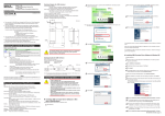
5. Double-click SETUP.EXE and the installation interface of MTC SET is shown as below.
6. Enter the installation window of MTC SET shown below, and click NEXT to enter the next step of
installation.
2
7. By clicking “Change” button, you can modify the installation path, and then click NEXT to enter the next
step of installation.
8. Click “Install” button, and the installation program proceed to the automated installation procedure.
3
9. Click Finish button to complete the installation process.
4
1.3 Procedure
After completing installation procedure, MTC SET procedure has been established in the
designated default subdirectory "C:\Program Files\MTC-3", here directly click MTC SET icon to implement
the set-editing software, then the start window of MTC SET set-editing software is appeared as follows.
After three seconds MTC SET set-editing window will appear as follows. If you do not select
『New』,『Open』or『Upload』while first opening MTC SET, window only show『File(F)』、
『Communication(C)』、『Option(O)』and『Help(H)』menu.
5
After selecting『File』→『New』, the models selection window will appear as follows.
After OK button, a set-editing window will show as follows.
6
If you click 『File』→『Open』or『Communication』→『Upload』, the corresponding function and setting
windows will be open. MTC SET set-editing window is shown as an example in the following figure.
■ Window bar
:Show the current file name.
■ Menu bar
:Show 6 main options in the menu bar, including『File(F)』,『Function Selection(A)』,
『Communication(C)』,『Monitor(M)』,『Option(O)』and『Help(H)』.
■ Icon bar
:Select your required function button directly by clicking the shortcut .
■ Edit window
:Edit the set value, then directly download it into the MTC-3 machine, that can reduce
more inconvenience for operating and setting on MTC-3 machine.
■ Status bar
:Show many messages including model, communication port, communication format,
station No. etc.
7
2.0 Brief Introduction
MTC SET has launched the first window as below, which has only the four options, including File
(F), Communication(C), Option(O)and Help(H).
After selecting the new file under the pull-down menu of『File(F)』menu, a new window will be
shown as below, which add the other options such as『Function Selection(A)』 and Monitor(M)』.
8
2.1
File(File)Option
The pull-down menu of『File(F)』is shown as below, which can provide the following options.
■
2.1.1
New
New File
Explanation
Create a new set-editing file and close the current set-editing file
◎ Method 1:Click『New(N)』under『File(F)』menu
Operation Method
◎ Method 2:Click
icon in the icon bar
◎ Method 3:Enter〔Ctrl〕+〔N〕by shortcut key
■
2.1.2 Open
Open
Explanation
Open the old file saved in disk drive and close the current set-editing file
◎ Method 1:Click『 Open(O)』under『File(F)』menu
Operation Method
◎ Method 2:Click
icon in the icon bar
◎ Method 3:Enter〔Ctrl〕+〔O〕by shortcut key
9
■
2.1.3 Close
Close
■
Explanation
Close the current editing project
Operation Method
◎ Method:Click 『Close(C)』under『File(F)』menu
2.1.4 Save
Save
Explanation
Save the current editing data file into the disk drive
◎ Method 1: Click 『Save(S)』under『File(F)』menu
Operation Method
◎ Method 2: Click
icon in the icon bar
◎ Method 3: Enter〔Ctrl〕+〔S〕by shortcut key
10
■
2.1.5 Save as
Save as
Explanation
Operation Method
Save the current file into the other file name
◎ Method 1: Click 『Save as(S)』under『File(F)』menu
◎ Method 2: Enter〔Ctrl〕+〔A〕by shortcut key
■
2.1.6 Exit
Exit
Explanation
Operation Method
Exit MTC SET window
◎ Method 1: Click 『Exit(X)』under『File(F)』menu
◎ Method 2: Click
11
icon on the top right corner window
2.2 Function Selection Option
The pull-down menu of 『Function Selection(A)』will appear different options according the different
models, as shown below.
■
2.2.1 MTC-3 models:
Timer
Explanation
Operation Method
Set function as Timer
◎ Method: Click 『Timer』under『Function Selection(A)
』menu
Twin Timer
Explanation
Operation Method
Set function as Twin Timer
◎ Method: Click 『Time Timer』under『Function Selection(A)
』menu
2-Stage Timer
Explanation
Operation Method
Set function as 2-Stage Timer
◎ Method: Click 『2-Stage Timer』under『Function Selection(A)
』menu
1-Stage Counter
Explanation
Operation Method
Set function as 1-Stage Counter
◎ Method: Click 『1-stage Counter』under『Function Selection(A)
』menu
2-Stage Counter
12
Explanation
Operation Method
Set function as 2-Stage Counter
◎ Method: Click 『2-stage Counter』under『Function Selection(A)
』menu
Total Counter
Explanation
Operation Method
Set function as Total Counter
◎ Method: Click 『Total Counter』under『Function Selection(A)
』menu
Batch Counter
Explanation
Operation Method
Set function as Batch Counter
◎ Method: Click 『Batch Counter』under『Function Selection(A)』menu
Twin Counter
Explanation
Operation Method
Set function as Twin Counter
◎ Method: Click 『Twin Counter』under『Function Selection(A)
』menu
Tachometer
Explanation
Operation Method
Set function as Tachometer
◎ Method: Click 『Tachometer』under『Function Selection(A)
』menu
13
2.3
Communication(Communication)Option
The pull-down menu of『Communication( C )』will offer 3 options as shown below.
■
2.3.1 Upload(Device → PC) :
Upload ( Device → PC )
Explanation
[note 1]
Communicate between PC and MTC-3 series models, read and show the
current set value
◎ Method 1: Click 『Upload(Device → PC)』under『Communication(C)』
Operation Method
menu
◎ Method 2: Click
icon in the icon bar
◎ Method 3: Enter〔F11〕by shortcut key
■
2.3.2 Download(PC → Device) :
Download ( PC → Device )
Explanation
[note 1]
Communicate between PC and MTC-3 series models, and download the set
value on PC into MTC-3 series models
◎ Method 1: Click 『Download (PC → Device)』under『Communication(C)』
Operation Method
menu
◎ Method 2: Click
icon in the icon bar
◎ Method 3: Enter〔F9〕by shortcut key
14
■
2.3.3 Compare (PC <--> Device)
Compare ( PC <-->Device )
[note 1]
Communicate between PC and MTC-3 series model, which can compare the
Explanation
set value on PC with the current value on MTC-3 series model and show the
differences.
◎ Method 1: Click 『Compare(PC → Device)』under『Communication(C)』
Operation Method
menu
◎ Method 2: Enter〔F8〕by shortcut key
※ [Note 1] : you must set the communication COM port, communication format and station No.
before communicating.
2.4
Monitor(Monitor)Option
The pull-down menu of『Monitor( M )』will shown below.
■
2.4.1 Monitor
Monitor
Explanation
Enter the monitor screen
◎ Method 1: Click 『Monitor』under『Monitor(M)』menu
Operation Method
◎ Method 2: Click
icon in the icon bar
◎ Method 3: Enter〔Ctrl + M〕by shortcut key
15
The monitor window is shown as follows.
■
『START』button : Start to communicate MTC-3 series model with PC after pressing START button,
and read the set value, current value and other set value, as shown in the above figure.
■
『STOP』button : Stop the communication with MTC-3 series model.
■
『RETURN』button : Return to the former set window.
■
Monitor window : Show the present value, the set value, output status and key-protection switch etc.
■
Setting information window: It can automatically judge and show the model and the other settings at
the beginning of monitoring.
16
■
2.4.2 Return
Return
Explanation
Operation Method
Return to the former set screen
◎ Method 1: Click 『Return』under『File(F)』menu
◎ Method 2: Click 『RETURN』button
■
2.4.3
Communication Settings
Communication Settings
Explanation
Enter to the set screen
◎ Method 1: Click 『communication settings』under『Operation( O )』menu
Operation Method
◎ Method 2: Click
icon in the icon bar
◎ Method 3: Enter〔Ctrl + U〕by shortcut key
Refer to section 2.5.1 for details on the setting method.
■
2.4.4
Logging
17
Logging
Explanation
Enter to the logging set screen
Operation Method
◎ Method 1: Click 『Logging』under『Option( O )』menu
The logging screen is shown as bellow:
■
■
Log rate : Set the time interval for logging, and only record the current value
Log error : It will record “Error” without read the current value successfully when selecting this
option is selected.
■
Delimit: Set the delimit sign for every data
Start to log the current value and save it to log file while pressing OK. While the communication is
paused the record will be stopped. It will continue to the previous record again unless going back to
communicate. While you press “stop record”, record will be end.
18
2.5
Option
The pull-down menu of『Option(O)』will shown below.
■
2.5.1
Communication Settings
Communication Settings
Explanation
Operation Method
Enter to the communication set screen
◎ Method 1: Click 『communication settings』under『Option( O )』menu
◎ Method 2: Enter〔Ctrl + U〕by shortcut key
The communication settings screen is shown as bellow:
19
■ Communication port: The default COM1
■ Communication format: Set the communication format
→ Communication speed: the default 9600 Bps
→ Data bit: the default 8 bits
→ Parity: None
→ Stop bit: the default 1 bits
■ Communication response time: The maximum waiting time for response after sending data, the
default value is 100ms,the minimum value can not be set below 50ms
■ Communication delay time: The delay time for sending the next data after receiving data, the default
value is 0 ms
■ Communication Protocol: Only MODBUS ASCII supported
■ Communication station setting: Set the communication station NO., which can be divided into Manual
Setting and Automatic Search
■ Manual Setting: Set the communication station No. by manual, the range value is
01~FF (Hex), the default value is 01.
■ Automatic Search: Automatically search the current station No. from 01 to FF (Hex) for MTC-3
according the current communication port and format. If not searching,
please be sure that the communication format is same between PC and
MTC-3 and the communication response time is too short. If lots of MTC-3
machines are running at the same time, all of station No. and models will
be list, you can choice your desired station No. and press OK or APPLY
button.
20
※ The current setting state does not be changed until pressing APPLY or OK button. If you want
to change the set value while using automatic search, you must press APPLY button to change
the current setting state and then search.
■
2.5.2
Key Protection
Key Protection
Explanation
Set key enable/unable according the current Key Protection Level to prevent
user misoperation.
◎ Method 1: Click 『Key Protection』under『Option』menu
Operation Method
◎ Method 2: Click
icon in the icon bar
◎ Method 3: Enter〔Ctrl + K〕by shortcut key
21
2.6
Help(Help)Option
The pull-down menu of『Help( H )』will shown below.
■
2.6.1
About me
About me
Explanation
Operation Method
Show MTC SET version and correlative information
◎ Method: Click『About me』under『Help(H)』menu
22