Download 64 KB - Test Equipment Depot
Transcript
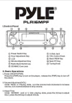
Test Equipment Depot 99 Washington Street Melrose, MA 02176-6024 www.testequipmentdepot.com FREQUENCY COUNTER 800-517-8431 781-665-0780 FAX FREQUENCY COUNTER USER MANUAL USER MANUAL CONTENTS PAGE 1. PRODUCT INTRODUCTION............................................. 1 1-1.Description… … … … … … … … … … … … … … … … … … . 1 1-2.Feature… … … … … … … … … … … … … … … … … … … ... 1 i 2. TECHNICAL SPECIFICAT ION… … … … … … … … … … ... 2 3. PRECAUTIONS BEFORE OPERATION… … .… … … … ... 3-1.Unpacking the Instrument… … … … … … … .… … … … ... 3-2.Checking the Line Voltage… … … … … … … ..… … … … . 3-3.Equipment Installation and Operation… … … … … … ... 3-4.General Preparation… … … … … … … … … … … … … … .. 3 3 3 4 4 4. PANEL INTRODUCTION… … … … … … … … ..… … … … … 5 5. APPLICATION… … … … … … … … … … … … … … … … … … . 7 5-1.Sensitivity… … … … … … … … … … … … … … … … … … … 7 5-2.Input Sensitivity Characteristic… … … … … … … … … ... 10 5-3.Maximum Input Voltage… … … … … … … … … … … … ... 11 5-4.Typical Applications… … … … … … … … … … … … … … .. 11 6. CIRCUIT DESCRIPTION… … … … … … … … … … … ...… ... 13 6-1.Theory of O peration… … … … … … … … … … … … ..… .... 13 6-2.Frequency Measurement Accuracy… … … … … … … … . 14 7. MAINTENANCE… … … … … … … … … … … … … … … … … .. 18 7-1.Standard Method for Calibration… … … … … … … … … 18 7-2.Cleaning… … … … … … … … … … … … … … … … … … … ... 18 1 Test Equipment Depot 99 Washington Street Melrose, MA 02176-6024 www.testequipmentdepot.com FREQUENCY COUNTER 800-517-8431 FREQUENCY COUNTER USER MANUAL 4. PANEL INTRODUCTION (1). Counter Input BNC type connector. (2). ATT, 1/1, 1/10 Attenuation button of input sensitivity. 1/1 : Directly connect input signal to input amplifiers. 1/10: Attenuate input signal by a factor of 10. (3). LPF ON/OFF Set to ON position, insert a 100kHz Low Pass Filter into input for low frequency measurement. (4). FREQ/PRID 781-665-0780 FAX USER MANUAL l Front Panel 7 8 FREQUENCY COUNTER MAX. INPUT VOLTAGE 5Hz ∼100KHz 150V RMS 0.1 ∼120MHz 5V RMS INPUT 1MW 150V AC MAX 10 MODEL : GFC-8010H OVER m GATE Frequency or period measurement by setting the button. (5). Gate Time Selector Press the gate time button to 10 sec, 1 sec or 0.1 sec for measurement. 9 ATT LPF 1/1 ON 1/10 OFF FREQ PRID GATE TIME 0.1 1 (SEC) 10 K M Hz m n ON OFF 5Hz ∼120MHz (6). Power ON/OFF Power on or off by using the button. (7). Gate Time(LED) The gate time of 10 sec, 1 sec or 0.1 sec will be displayed in the LED by setting the Gate button. (8). Over (LED) Overflow indicator shows that one or more of the most significant digits are not displayed. (9). Displayed (LED) Display 8 digits of frequency data. 1 2 3 4 5 Fig. 1 Front panel (10) Exponent and units LED indicator shows S and Hz of the unit and indicate (LED) the value of the measurement exponent as shown below: k=1000 M=1,000,000 G=1,000,000,000 m=1/1000 μ=1/1,000,000 n=1/1,000,000,000 6 7 6 s Test Equipment Depot 99 Washington Street Melrose, MA 02176-6024 FREQUENCY COUNTER www.testequipmentdepot.com 800-517-8431 781-665-0780 FAX FREQUENCY COUNTER USER MANUAL USER MANUAL 5. APPLICATION As refer to Fig. 2, when input voltage is at V+, the output voltage is high 5-1. Sensitivity (VOH), while input voltage is at V- , the output voltage is low (VOL ). The The role of the SENSITIVITY (or attenuator) switch in a common difference between these two voltage VH =(V+ )- (V- ) is called the measuring instrument is to protect the input circuit and prevent the meter hysteresis voltage. from going off scale. But if both V+ and V- don’t react each other, no output will be obtained For a counter, SENSITIVITY is still one of the large roles. Generally, and the Schmitt circuit will not work out with the states of (1), (2) and (3) hysteresis occurs in the waveshaping circuit of the counter. In order for the of Fig. 3 shown as below. instrument to put up resistance to noise, the circuit will not work even when the noise is lower than the hysteresis applied. The waveshaping V+ circuit is a Schmitt circuit and the operation of this circuit is described below: VH V(1) VH=(V+) - (V-) VH: Hysteresis voltage (2) (3) Fig. 3 States under which the schmitt circuit doesn’t work Input Voltage V+ VH Output Voltage Fig. 2 Operation of the Schmitt circuit V- From above description, it can be easily understood whether or not the V OH Schmitt circuit works is attributed to the SE NSITIVITY (Attenuator) to V OL determine the magnitude of the input voltage. An example of preventing erroneous counting by correctly selecting the SENSITIVITY shown as Fig. 4 below: (a) Correctly counting a distortion signal by selecting suitable SENSITIVITY. However, when the input voltage is too high, a frequency doubles the unknown frequency will be indicated. (b) Erroneous counting occurs when high frequency noise is superimposed on the unknown signal and the input voltage of the Schmitt circuit is too high. Howev er, a correct counting can be obtained by selecting suitable SENSITIVITY. 8 9 Test Equipment Depot 99 Washington Street Melrose, MA 02176-6024 FREQUENCY COUNTER www.testequipmentdepot.com 800-517-8431 781-665-0780 FAX FREQUENCY COUNTER USER MANUAL USER MANUAL The erroneous counting can be prevented by satisfying two conditions below: a)To make peak-to-peak value of the noise voltage smaller than VH . b) When peak-to-peak value of unknown signal is larger than VH , perform measurements by first setting SENSITIVITY to 1/10, then set it to 1/1 range to protect the input circuit and avoid erroneous counting. One good method is to conduct measurements at the smallest possible input within the counter display value “dispersion” range. When the signal is a pure waveform, it will not occur erroneous counting with any magnit ude input lower than the input destroyed voltage. (a) When unknown signal is distorted 5-2. Input Sensitivity Characteristic The input sensitivity of this instrument is shown as Fig. 5. SENSITIVITY (mVrms) 200 150 100 GFC-8010H 50 40 20 10 (b) When high frequency noise superimposed on unknown signal Fig. 4 10 F 0 100Hz 30MHz 60MHz 120MHz Fig. 5 Input Sensitivity Characteristic 11 150MHz Test Equipment Depot 99 Washington Street Melrose, MA 02176-6024 FREQUENCY COUNTER www.testequipmentdepot.com 800-517-8431 781-665-0780 FAX FREQUENCY COUNTER USER MANUAL USER MANUAL 2).Measurement can also be easily performed when calibrating the oscillation frequency of a grid dip meter by merely connecting the one 5-3. Maximum input voltage The maximum input voltage Vs frequency characteristics is shown as Fig. 6. turn clip cord. 3).Measurement of tracking the frequency through the oscillator stage, multiplier stage, and output stage can be performed by making a small 2-3 turn coil and coupling it to each turned circuit (the oscillations INPUT VOLTAGE (Vrms) may be produced by the input capacitance and its resonant frequency 150 NOTE :These Values must not be exceeded when the signal contains a DC Component ( DC Voltage + peak AC Voltage ) with too many turns of coil.) Note: As the product has a high sensitivity, induction may cause erroneous counting if you touch the red end (ungrounded side) of 100 the clip cord. Therefore, hold the black clip or coaxial cable when performing measurements according to above method. 50 Measurement by connecting the accessory cable directly to the test circuit is described below. 10 4).Measurement can generally be performed by merely connecting the black side of the clip cord to ground (GND) and the red side to the test 5 0 F 1KHz 50 100KHz 1MHz 100 150 point. 5).When the capacitance of the cable will have an affection on the test circuit (When measuring turned circuits or high output impedance Fig. 6. Maximum Input Voltage -Frequency circuit), perform measurement by inserting a high resistance in series with the red side of the clip cord. Always be sure to ground the cord when perform the measurement of 4) and 5) above. If possible, ground the cable to the ground point of the test circuit. This procedure will 5-4. Typical Applications Several examples for typical applications are described below: reduce the affection of noise. A wide variety of measurement can be 1).The output frequency of a transmitter or transceiver can be measured conceived in addition to (1~5) fully utilizing the special features of the (if the output power is about 1W) by merely connecting a one turn clip counter. cord to several tens of centimeters from antenna. The length of the distance is determined by the magnitude of the output. 12 13 Test Equipment Depot 99 Washington Street Melrose, MA 02176-6024 FREQUENCY COUNTER www.testequipmentdepot.com 800-517-8431 781-665-0780 FAX FREQUENCY COUNTER USER MANUAL 6. CIRCUIT DESCRIPTION 6-1. Theory of Operation USER MANUAL 6-2. Frequency Measurement Accuracy Measurement Accuracy In order to get the most benefit from the frequency counter, it’s useful to Frequency measurement accuracy is determined by the following two comprehend the circuit thoroughly. We have attempted every possible to conditions: utilize the latest developments in large - scale integration to provide the greatest performance for the money and, at the same time, to reduce the complexity of circuit and increase reliability. Ignoring the prescaler for the moment, let us assume the input signal arrives at the 10MHz to 100MHz input labeled CHA in main board. This 1) ±1count. 2) Time base accuracy. The ±1 count error is inherent to digital meters and is produ ced by the signal is first amplified by the Q201~Q202 pair. The three amplifier phase relationship between the gate signal and the input signal shown in stages identified as U202 in the schematic are ECL logic stages biased in Fig. 7. The counted result of 1 count increased or decreased depends on its linear region, each stage having a gain before feedback of about 5. A the phase difference. positive feedback at the output of the third amplifier when reflected through the gain of the proceeding three amplifier states (including the Gate Signal Q201~Q202 pair) results in about a 5mV hysteresis in the input triggering 2 counts levels to aid in noise rejection. Q203 and Q204 translate the ECL levels to TTL levels. The signal is presented directly to the counter IC U3 01. Shaped output The IC U301 provides all the functions of the counter and display result 3 counts through LED. U201 regulates the input 9 volts signal from the line voltage transformer Shaped output and rectifier circuit. When the power switch is set to “on” position, approximately 5.0 volts is applied to the circuit. 14 Fig. 7 ±1 count error 15


