1
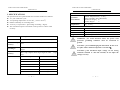
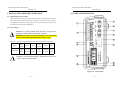
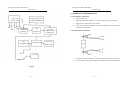
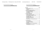
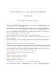
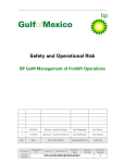
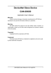
GOM-801H DC MILLI-OHM METER
USER MANUAL
Declaration of Conformity
We
CONTENTS
PAGE
GOOD WILL INSTRUMENT CO., LTD.
1. PRODUCT INTRODUCTION ............................................................1
No. 7-1, Jhongsing Rd, Tucheng City, Taipei County 236, Taiwan
GOOD WILL INSTRUMENT (SUZHOU) CO., LTD.
No.69 Lushan Road, Suzhou New District Jiangsu, China.
declares that the below mentioned product
GOM-801H
are herewith confirmed to comply with the requirements set out in the Council Directive on
the Approximation of the Law of Member States relating to Electromagnetic Compatibility
(89/336/EEC, 92/31/EEC, 93/68/EEC) and Low Voltage Equipment Directive
(73/23/EEC, 93/68/EEC).
For the evaluation regarding the Electromagnetic Compatibility and Low Voltage
Equipment Directive, the following standards were applied:
◎ EMC
2. SPECIFICATIONS ...............................................................................2
3. PRECAUTIONS BEFORE OPERATION .........................................4
3-1. UNPACKING THE INSTRUMENT ..........................................................4
3-2. LINE VOLTAGE ..................................................................................4
4. PANEL INTRODUCTION...................................................................5
5. CIRCUIT DESCRIPTION ...................................................................7
EN 61326-1: Electrical equipment for measurement, control and laboratory use –– EMC
requirements (1997+A1: 1998 +A2:2001+A3:2003)
Electrostatic Discharge
Conducted and Radiated Emission
IEC 61000-4-2: 2001
EN 55011: 1998+A1:1999 + A2:2002
Group I class B
Current Harmonic
Radiated Immunity
IEC 61000-3-2: 2000
IEC 61000-4-3: 2002+A1:2002
Voltage Fluctuation
Electrical Fast Transients
IEC 61000-3-3: 1995+A1:2001
IEC 61000-4-4: 1995+A1:2001+A2:2001
Surge Immunity
------------------------IEC 61000-4-5: 2001
Conducted Susceptibility
------------------------IEC 61000-4-6: 2001
Power Frequency Magnetic Field
------------------------IEC 61000-4-8: 2001
Voltage Dips/ Interrupts
------------------------IEC 61000-4-11: 2004
6. OPERATION INTRODUCTION .................................................9
6-1. PRELIMINARY OPERATION.................................................................9
6-2. MEASUREMENT OF RESISTOR ............................................................9
6-3. MEASUREMENT OF SWITCH .............................................................10
7. MAINTENANCE.................................................................................11
7-1. LINE FUSE REPLACEMENT ................................................................11
7-2. CLEANING........................................................................................11
◎ Safety
Low Voltage Equipment Directive 73/23/EEC & amended by 93/68/EEC
IEC / EN 61010-1: 2001
⎯
i ⎯
GOM-801H DC MILLI-OHM METER
GOM-801H DC MILLI-OHM METER
USER MANUAL
USER MANUAL
SAFETY TERMS AND SYMBOLS
FOR UNITED KINGDOM ONLY
These terms may appear in this manual or on the product:
NOTE: This lead/appliance must only be wired by competent persons
WARNING. Warning statements identify condition or
practices that could result in injury or loss of life.
WARNING: THIS APPLIANCE MUST BE EARTHED
IMPORTANT: The wires in this lead are colored in accordance with
CAUTION. Caution statements identify conditions or
practices that could result in damage to this product or
other property.
WARNING: This equipment is not for measurements
performed for CAT II, III and IV.
The following symbols may appear in this manual or on the product:
the following code:
Green/ Yellow:
Blue:
Brown:
Earth
Neutral
Live (Phase)
As the colors of the wires in main leads may not correspond with the
colors marking identified in your plug/appliance, proceed as follows:
The wire which is colored Green & Yellow must be connected to the
Earth terminal marked with the letter E or by the earth symbol
or colored Green or Green & Yellow.
The wire which is colored Blue must be connected to the terminal
which is marked with the letter N or colored Blue or Black.
DANGER
ATTENTION
High Voltage refer to Manual
Protective
Conductor
Terminal
Earth(ground)
Terminal
The wire which is colored Brown must be connected to the terminal
marked with the letter L or P or colored Brown or Red.
If in doubt, consult the instructions provided with the equipment or
contact the supplier.
⎯ ii ⎯
⎯ iii ⎯
GOM-801H DC MILLI-OHM METER
GOM-801H DC MILLI-OHM METER
USER MANUAL
This cable/appliance should be protected by a suitably rated and
approved HBC mains fuse: refer to the rating information on the
equipment and/or user instructions for details. As a guide, cable of
0.75mm2 should be protected by a 3A or 5A fuse. Larger conductors
would normally require 13A types, depending on the connection
method used.
Any mounded mains connector that requires removal /replacement
must be destroyed by removal of any fuse & fuse carrier and disposed
of immediately, as a plug with bared wires is hazardous if a engaged
in live socket. Any re-wiring must be carried out in accordance with
the information detailed on this label.
⎯ iv ⎯
USER MANUAL
1. PRODUCT INTRODUCTION
The Digital Milliohm Meter features with its accuracy and readability. The
circuit of this instrument has equipped with the voltage regulator and
temperature compensation in order for its accuracy not to be influenced by
the unstable AC power source and the alternation of temperature.
The Digital Milliohm Meter is specially produced for the manufacturers of
the low resistor, switch, relay, jacks, plugs, connectors sockets or the electrolytic
capacitor for the QC or IQC purpose, it also can be applied to measure the initial
contact resistance.
⎯ 1 ⎯
GOM-801H DC MILLI-OHM METER
GOM-801H DC MILLI-OHM METER
USER MANUAL
USER MANUAL
2. SPECIFICATIONS
Environment
The specifications are operated under the essential conditions as follows:
z A 1-year calibration cycle.
z An operating temperature of 18 to 28℃ (64.4 to 82.4℉).
z Relative humidity not exceeding 80%.
z Accuracy is expressed as ±(percentage of reading + digits).
z The instrument requires 30 minutes warm-up time to achieve rated
accuracy.
Operation
Environment
Indoor use, altitude up to 2000m.
Ambient Temperature 0℃ to 40℃.
Relative Humidity 80% (Maximum).
Installation category II
Pollution Degree
2
Storage
Temperature
-10℃ to 70℃.
Meter
3 1/2 Digital Panel Meter.
Test Current
10uA, 100uA, 1mA, 10mA, 0.1A, 1A
Power source
Accessories
Dimension
Weigh
AC 100V/120V/220V/230V±10%, 50/60Hz, 25VA
Test Lead × 1, Instruction manual × 1
245(W)×95(H)×280(D) m/m
Approx. 2 kg
WARNING : To avoid electrical shock, the power cord
Accuracy:0.2%
Hi/Go/Lo Compare
0.5%
Accuracy
Test Ranges
20, 200mΩ, 2, 20, 200Ω, 2, 20kΩ totally 7 full scale
ranges.
Accuracy
±0.2% rdg+4 digits(±0.2% rdg+6 digits for 20mΩ range
only)
Range
Current
20, 200mΩ
1A
2Ω
0.1A
20Ω
10mA
200Ω
1mA
2kΩ
100μA
20kΩ
10μA
⎯ 2 ⎯
General
protective grounding conductor must be connected to
ground.
CAUTION:To avoid damaging the instrument, do not use it
in a place where ambient temperature exceeds 40℃.
CAUTION : The maximum input voltage on the testing
terminal is limited at +10V DC. Besides, do not input the
voltage reversely.
⎯ 3 ⎯
GOM-801H DC MILLI-OHM METER
GOM-801H DC MILLI-OHM METER
USER MANUAL
USER MANUAL
4. PANEL INTRODUCTION
3. PRECAUTIONS BEFORE OPERATION
3-1. Unpacking the Instrument
The product has been fully inspected and tested before shipping from the factory.
Upon receiving the instrument, please unpack and inspect it to check if there is
any damage caused during transportation. If any sign of damage is found, notify
the bearer and/or the dealer immediately.
3-2. Line Voltage
WARNING. To avoid electrical shock the power cord protective
grounding conductor must be connected to ground.
AVERISS: Pour éviter les chocs électriques, le fil de terre du
cordon secteur doit impérativement être relié à la terre.
When line voltages are changed, replace the required fuses shown as below:
Line
Model
Range
Fuse
voltage
GOM-801H
100V
120V
90-110V TT0.3A
108-132V 250V
Line
voltage
220V
230V
Range
Fuse
198-242V
216-250V
T0.2A
250V
WARNING. To avoid personal injury, disconnect the power cord
before removing the fuse holder.
Figure 4-1. Front Panel
⎯ 4 ⎯
⎯ 5 ⎯
GOM-801H DC MILLI-OHM METER
GOM-801H DC MILLI-OHM METER
USER MANUAL
5. CIRCUIT DESCRIPTION
Front Panel
1. Power Switch
2. Range
3. HI/LO
4. SET/TEST
5. FORCE Terminal “+”
USER MANUAL
Power on/off switch.
z
7 steps: 20, 200mΩ, 2, 20, 200Ω, 2 and 20kΩ.
Set the “SET/TEST” switch to “SET” position,
DVM Circuit
The DVM is an A/D converter by using IC U301.
z
10 or 100 Times Signal Amplifier
The signal amplifier uses IC U401.
then select HI/LO for high or low value setting.
This button can be used for testing or HI/LO
z
There are 7 steps of Test ranges to be selected. It will not affect its
accuracy due to the alternation or temperature.
value setting.
Test terminal.
6. SENSOR Terminal “+” Test terminal.
Test Range selected buttons
z
Constant Current Source
7. SENSOR Terminal “-” Test terminal.
The circuit uses IC U201and U202 and transistors Q203 and Q204 to
8. FORCE Terminal “-”
Test terminal.
produce constant current.
9. HI of Comparator Set
For high value setting.
z
10. LO of Comparator Set For low value setting.
11. Panel Meter
12. HI Indicator
14. LO Indicator
comparator use IC U403 and U404. The HI, GO and LO indictors use
This indicator will be lighted up when the test
This indicator will be lighted up when the test
13. GO Indicator
The setting is consists of the resistors and the variable resistors. The
To indicate the test value.
value is higher than the setting of high value.
Comparator Set and HI, GO and LO Indicators
transistors Q401~Q407.
z
Voltage Regulator Circuit
value between high and low setting. The buzzer
The power supply has regulated output of ±5V and ±15V voltage, which
will be sounded up 2~5 seconds when the GO
are regulated by using Q201, Q202 and Q301 resistors to control D201,
indicator is on.
D202 and D301 zener diodes. The +5V voltage regulator circuit uses IC
This indicator will be lighted up when the test
U302 voltage regulator.
value is lower than the setting of low value.
⎯ 6 ⎯
⎯ 7 ⎯
GOM-801H DC MILLI-OHM METER
GOM-801H DC MILLI-OHM METER
USER MANUAL
USER MANUAL
6. OPERATION INTRODUCTION
VOLTAGE
RANGE SELECTOR
REGULATOR
& MEASUREMENT
CONSTANT
CURRENT
SOURCE
TEST
TERMINAL
SET
REFERENCE
SET
COMPARATOR
6-1. Preliminary Operation
1. Set the power off.
2. Make sure that line voltage is correct for the input power voltage.
3. Plug power cord into the power outlet.
4. Turn on the instrument and allow about 10 minutes of warm up time to
stabilize the instrument.
10 OR 100
TIMES SIGNAL
AMPLIFIER
6-2. Measurement of Resistor
HI.GO.LO
INDICATOR
31/2 DVM
TEST
Fig. 6-1
1.
Connect an unknown resistor to the test terminals as shown in Fig. 6-1.
2.
Set the range to the position where the reading value can be obtained.
Fig. 5-1
⎯ 8 ⎯
⎯ 9 ⎯
GOM-801H DC MILLI-OHM METER
GOM-801H DC MILLI-OHM METER
USER MANUAL
USER MANUAL
7. MAINTENANCE
6-3. Measurement of Switch
Qualified personnel execute the following instructions only. To avoid
electrical shock, do not perform any servicing other than the operating
instructions unless you are qualified to do so.
7-1. Line fuse replacement
If the fuse blows, the meter would not work. Try to determine and correct
the cause of the blown fuse, then replace the fuse with correct rating and
type shown as below:
FUSE RATING AND TYPE
Fig. 6-2
1.
Connect the switch to be tested as shown in Fig. 6-2.
2.
Set the range to the position where the reading value can be obtained.
100/120V
TT0.3A
220/230V
T0.2A
WARNING: For continued fire protection, replace only
with 250V fuse of the specified type and rating, and
disconnect the power cord before proceeding fuse
replacement.
7-2. Cleaning
To keep the instrument clean, wipe the case with a damp cloth and
detergent. Do not use abrasives or solvents.
⎯ 10 ⎯
⎯ 11 ⎯