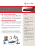
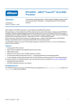
1
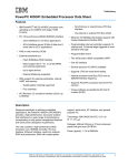
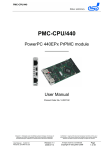
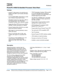
440EPx – PPC440EPx Embedded Processor
Revision 1.12 – April 25, 2007
Preliminary User’s Manual
24.2 DMA to PLB3 Controller (DMA2P30)
DMA to PLB3 is attached to the 64-bit processor local bus. Table 24-6 lists the DMA2P30 channel assignments in
PPC440EPx.
Table 24-6. DMA to PLB 3 Channel Assignments
Channel
Sub-Channel
DMA Internal Source
Sub-Channel 0
UART 0 Receive
Sub-Channel 1
UART 2 Receive
DMA External Source
Sub-Channel 2
Sub-Channel 3
Channel 0
Sub-Channel 4
Sub-Channel 5
Sub-Channel 6
Sub-Channel 7
Sub-Channel 0
UART 0 Transmit
Sub-Channel 1
UART 2 Transmit
Sub-Channel 2
Sub-Channel 3
Channel 1
Sub-Channel 4
Sub-Channel 5
Sub-Channel 6
Sub-Channel 7
Sub-Channel 0
UART 1 Receive
Sub-Channel 1
UART 3 Receive
Sub-Channel 2
Sub-Channel 3
Channel 2
Sub-Channel 4
Sub-Channel 5
Sub-Channel 6
Sub-Channel 7
AMCC Proprietary
625
440EPx – PPC440EPx Embedded Processor
Revision 1.12 – April 25, 2007
Preliminary User’s Manual
Table 24-6. DMA to PLB 3 Channel Assignments (continued)
Channel
Sub-Channel
DMA Internal Source
Sub-Channel 0
UART 1 Transmit
Sub-Channel 1
UART 3 Transmit
DMA External Source
Sub-Channel 2
Sub-Channel 3
Channel 3
Sub-Channel 4
Sub-Channel 5
Sub-Channel 6
Sub-Channel 7
24.2.1 External Interface Signals
Figure 24-13 illustrates the external I/Os associated with the DMA controller and the EBC I/Os used during external
peripheral transfers. External peripheral and EBC device-paced memory transfers request service from the DMA
controller by driving a DMA request line (DMAReq0-3) active. For peripheral mode transfers the DMA controller
acknowledges the request and transfers data by asserting a DMA acknowledge signal (DMAAck0-3). In contrast,
an EBC device-paced memory-to-memory transfer occurs when the chip select (PerCSn) associated with the
memory location is driven active. The timing of PerCSn and the other EBC I/Os is determined by the Bank Access
Parameter Register (EBC0_BnAP) for the particular memory location. See External Bus Controller on page 565 for
details on EBC configuration and timings.
Table 24-7. DMA to PLB3 Controller External I/Os
Signal
Usage
DMAReqn
DMA Request, used to request either a peripheral mode transfer or an EBC device-paced memory-to-memory transfer.
DMAAckn
DMA Acknowledge, instructs an EBC-attached DMA peripheral to transfer data.
EOTn[TCn]
End of Transfer or Terminal Count. Used to stop the channel when programmed as EOT. When configured as TC, goes
active when the channel transfer count register (DMA2P30_CTn) reaches zero.
Note: The active level (polarity) of the DMAReqn, DMAAckn, and EOTn[TCn] signals is individually programmable. See DMA to PLB 3 Polarity Configuration Register (DMA2P30_POL) on page 630.. Operating information and
timing waveforms are presented generically for active-high signals.
626
AMCC Proprietary
Revision 1.12 – April 25, 2007
440EPx – PPC440EPx Embedded Processor
Preliminary User’s Manual
Figure 24-13. DMA to PLB 3 External Bus Controller Signals
DMA to PLB3
Controller
DMAReq0
DMAAck0
EOT0[TC0]
DMAReq1
PLB
DMAAck1
EOT1[TC1]
DMAReq2
OPB
DMAAck2
EOT2[TC2]
DMAReq3
DMAAck3
EOT3[TC3]
PerClk
PerData0:31
EBC
Controlled
I/Os
PerR/W
PerOE
PerWBE0:3
DCR Bus
Configuration
and
Status
Registers
24.2.2 Functional Overview
As a specialized controller, the DMA unit provides system designers and programmers with a highly efficient
method of moving data. During any DMA transfer the controller always buffers data read from the source prior to
writing the data to the destination. Since many buses, including the internal PLB and the SDRAM interface, provide
substantially better performance when bursting data, the DMA controller includes a 32-byte (4 double words)
buffer. This buffer is enabled on a per-channel basis by setting DMA2P30_CRn[BEN] and serves to minimize the
number of discrete memory transactions. Each of the four DMA channels is configurable for either peripheral or
memory-to-memory transfers.
24.2.3 Peripheral Mode Transfers
Peripherals are either devices attached to the EBC interface via the DMAReqn and DMAAckn lines, or the internal
serial port (UART0). Memory is any address accessible from the PLB, including PLB-mapped PCI address space,
SDRAM memory, and memory and memory-mapped devices on the peripheral bus. During a peripheral mode
transfer the peripheral requests a DMA transfer by asserting a DMA request line. For UART0, this signal is internal
AMCC Proprietary
627
440EPx – PPC440EPx Embedded Processor
Revision 1.12 – April 25, 2007
Preliminary User’s Manual
to the PPC440EPx, while external peripherals use one of the DMAReqn lines. When the requesting channel has
the highest priority of any active channel, the requesting device receives a DMA acknowledge. In the case of
external peripherals, the appropriate DMAAckn line is driven to the active state, with the timing specified in the
DMA Control Register for the channel (DMA2P30_CRn).
There are two types of peripheral mode transfers: peripheral-to-memory and memory-to-peripheral. A peripheralto-memory transfer reads data from a DMA device, while a memory-to-peripheral transfer writes data. In both
cases, the peripheral interface never bursts and data is transferred at the width of the peripheral. If the DMA buffer
is disabled for the active channel (DMA2P30_CRn[BEN]=0), each peripheral transfer causes a corresponding
memory operation.
When buffering is enabled during a peripheral-to-memory transfer, data is collected until the 32-byte buffer is full,
the peripheral deasserts DMAReqn, a higher priority DMA request becomes pending, or the channel completes.
The buffer contents are then written to the target memory as efficiently as possible. If the initial programming of the
channel’s destination address register (DMA2P30_DAn) is 32-byte aligned, the buffer is emptied in one burst
operation to the target memory.
Memory-to-peripheral transfers differ since the amount of data that will be requested by the peripheral is unknown.
If the DMA buffer is disabled (DMA2P30_CRn[BEN]=0) a discrete source memory read occurs for each element in
the DMA transfer. Since this is inefficient, the buffer should only be disabled for low data rate transfers or when the
source memory is FIFO-like, and reads are therefore destructive. When the 32-byte buffer is enabled the controller
uses the setting in DMA2P30_CRn[PF] to prefetch 1, 2, or 4 64-bit double words from the source memory. The
DMA controller provides data from the buffer until the peripheral deasserts its request, the channel is interrupted by
one of higher priority, or the transfer completes. Whenever any of these conditions occurs any unused data in the
DMA buffer is discarded.
24.2.4 Memory-to-Memory Transfers
The DMA controller can perform either device-paced (hardware-initiated) or software-initiated memory-to-memory
transfers. Device-paced memory transfers function identically to peripheral mode transfers, except that a chip
select (PerCSn) serves as the DMA acknowledge instead of a DMAAckn output. As with peripheral mode
transfers, bursts never occur on the device-paced side of the transaction.
Software-initiated memory-to-memory transfers between memories with fixed timings provide the best overall
performance. During a software-initiated transfer the DMA controller knows the exact amount of data to be
transferred. As a result, when the 32-byte DMA buffer is enabled (DMA2P30_CRn[BEN]=1) the controller uses
bursts as much as possible. To ensure the highest bandwidth, source and destination addresses should be aligned
on 32-byte boundaries.
There are three cases that limit the ability to burst during software-initiated memory-to-memory transfers. Bursting
is not possible from the source memory when the source address increment is zero (DMA2P30_CRn[SAI]=0).
Similarly, the DMA controller does not burst to the destination when the destination address increment is zero
(DMA2P30_CRn[DAI]=0). Finally, the DMA controller cannot burst to or from any address that maps to a devicepaced (EBC0_BnAP[RE]=1) EBC chip select (PerCSn).
24.2.5 Scatter/Gather Transfers
Each of the four DMA channels supports scatter/gather transfers. This scatter/gather capability allows the chaining
of multiple DMA controller operations within a channel. During a normal DMA operation software must program the
control, source address, destination address, and count registers for each transfer. Scatter/gather transfers differ in
that these registers are automatically loaded from a linked list data structure in system memory. When a channel
completes one transfer the DMA controller loads the next set of configuration values into the channel’s registers
and the channel continues with the new programming.
628
AMCC Proprietary
440EPx – PPC440EPx Embedded Processor
Revision 1.12 – April 25, 2007
Preliminary User’s Manual
24.2.6 Configuration and Status Registers
Table 24-8 lists the DMA2P30 configuration and status registers, each of which is accessed using the mtdcr and
mfdcr instructions. As example, the following assembly code writes DMA2P30_CR0 and then reads
DMA2P30_SR:
#define DMA2P30_CR0
#define DMA2P30_SR
mtdcr
mfdcr
0x100
0x120
DMA2P30_CR0,r3
r4,DMA2P30_SR
! write r3 to channel 0 control register
! read contents of status register into r4
The DMA configuration and status registers are readable at any time. However, because each register read
requires a separate operation, it is not possible to guarantee that the values read from multiple registers
correspond to a state that ever existed in the DMA controller. To illustrate, consider software that reads the
destination address for channel 0 (DMA2P30_DA0) and then the count for channel 0 (DMA2P30_CT0). If the DMA
controller updates the count between these two operations, the values read differ from what is expected.
While reads can occur at any time, software must not write the configuration registers for any channel that is
currently enabled (DMA2P30_CRn[CE]=1). The only exception is that a channel may be disabled by reading the
channel control register, clearing the channel enable bit, and then writing the new value to the control register.
Once a channel is disabled, all of its configuration registers may be reprogrammed as desired.
Table 24-8. DMA to PLB 3 Controller Configuration and Status Registers
Mnemonic
DCR Address
Access
Description
Page
DMA2P30_CR0
0x0100
R/W
DMA to PLB 3 Channel Control Register 0
632
DMA2P30_CT0
0x0101
R/W
DMA to PLB 3 Count Register 0
634
DMA2P30_DA0
0x0102
R/W
DMA to PLB 3 Destination Address Register 0
634
DMA2P30_SA0
0x0103
R/W
DMA to PLB 3 Source Address Register 0
634
DMA2P30_SG0
0x0104
R/W
DMA to PLB 3 Scatter/Gather Descriptor Address Register 0
635
DMA2P30_SC0
0x0107
Page
DMA to PLB3 Subchannel ID for Register 0
636
DMA2P30_CR1
0x0108
R/W
DMA to PLB 3 Channel Control Register 1
632
DMA2P30_CT1
0x0109
R/W
DMA to PLB 3 Count Register 1
634
DMA2P30_DA1
0x010A
R/W
DMA to PLB 3 Destination Address Register 1
634
DMA2P30_SA1
0x010B
R/W
DMA to PLB 3 Source Address Register 1
634
DMA2P30_SG1
0x010C
R/W
DMA to PLB 3 Scatter/Gather Descriptor Address Register 1
635
DMA2P30_SC1
0x010F
Page
DMA to PLB3 Subchannel ID for Register 1
636
DMA2P30_CR2
0x0110
R/W
DMA to PLB 3 Channel Control Register 2
632
DMA2P30_CT2
0x0111
R/W
DMA to PLB 3 Count Register 2
634
DMA2P30_DA2
0x0112
R/W
DMA to PLB 3 Destination Address Register 2
634
DMA2P30_SA2
0x0113
R/W
DMA to PLB 3 Source Address Register 2
634
DMA2P30_SG2
0x0114
R/W
DMA to PLB 3 Scatter/Gather Descriptor Address Register 2
635
DMA2P30_SC2
0x0117
Page
DMA to PLB3 Subchannel ID for Register 2
636
DMA2P30_CR3
0x0118
R/W
DMA to PLB 3 Channel Control Register 3
632
DMA2P30_CT3
0x0119
R/W
DMA to PLB 3 Count Register 3
634
AMCC Proprietary
629
440EPx – PPC440EPx Embedded Processor
Revision 1.12 – April 25, 2007
Preliminary User’s Manual
Table 24-8. DMA to PLB 3 Controller Configuration and Status Registers (continued)
Mnemonic
DCR Address
Access
Description
Page
DMA2P30_DA3
0x011A
R/W
DMA to PLB 3 Destination Address Register 3
634
DMA2P30_SA3
0x011B
R/W
DMA to PLB 3 Source Address Register 3
634
DMA2P30_SG3
0x011C
R/W
DMA to PLB 3 Scatter/Gather Descriptor Address Register 3
635
DMA2P30_SC3
0x011F
Page
DMA to PLB3 Subchannel ID for Register 3
636
DMA2P30_SR
0x0120
R/Clear
DMA to PLB 3 Status Register
631
DMA2P30_SGC
0x0123
R/W
DMA to PLB 3 Scatter/Gather Command Register
635
DMA2P30_ADR
0x0124
R/W
DMA Address Decode Register
636
DMA2P30_SLP
0x0125
R/W
DMA to PLB 3 Sleep Mode Register
631
DMA2P30_POL
0x0126
R/W
DMA to PLB 3 Polarity Configuration Register
630
24.2.6.1 DMA to PLB 3 Polarity Configuration Register (DMA2P30_POL)
DMA2P30_POL is used to set the polarity (active state) of the external DMA I/O signals: DMAReqn, DMAAckn,
and EOTn[TCn]. As shown in Figure 24-14, if a bit in DMA2P30_POL is 0, the corresponding signal is active high,
otherwise the signal is active low.
Whenever any of the EOT polarities are changed (DMA2P30_POL[EnP), software must subsequently clear the
corresponding EOT status bits in DMA2P30_SR[TS0:3] before enabling the associated DMA channel. This is
necessary to prevent a channel from being disabled because of an incorrect EOT status stored in the status bits.
Figure 24-14. DMA to PLB3 Polarity Configuration Register (DMA2P30_POL)
630
0
R0P
DMAReq0 Polarity
0 DMAReq0 is active high
1 DMAReq0 is active low
1
A0P
DMAAck0 Polarity
0 DMAAck0 is active high
1 DMAAck0 is active low
2
E0P
EOT0[TC0] Polarity
0 EOT0[TC0] is active high
1 EOT0[TC0] is active low
3
R1P
DMAReq1 Polarity
0 DMAReq1 is active high
1 DMAReq1 is active low
4
A1P
DMAAck1 Polarity
0 DMAAck1 is active high
1 DMAAck1 is active low
5
E1P
EOT1[TC1] Polarity
0 EOT1[TC1] is active high
1 EOT1[TC1] is active low
6
R2P
DMAReq2 Polarity
0 DMAReq2 is active high
1 DMAReq2 is active low
7
A2P
DMAAck2 Polarity
0 DMAAck2 is active high
1 DMAAck2 is active low
8
E2P
EOT2[TC2] Polarity
0 EOT2[TC2] is active high
1 EOT2[TC2] is active low
AMCC Proprietary
Revision 1.12 – April 25, 2007
440EPx – PPC440EPx Embedded Processor
Preliminary User’s Manual
9
R3P
DMAReq3 Polarity
0 DMAReq3 is active high
1 DMAReq3 is active low
10
A3P
DMAAck3 Polarity
0 DMAAck3 is active high
1 DMAAck3 is active low
11
E3P
EOT3[TC3] Polarity
0 EOT3[TC3] is active high
1 EOT3[TC3] is active low
12:31
Reserved
24.2.6.2 DMA to PLB 3 Sleep Mode Register (DMA2P30_SLP)
DMA2P30_SLP enables the DMA controller to enter sleep (low-power) mode and programs the number of PLB
clock cycles to wait when the controller is idle before going to sleep. The DMA controller only goes to sleep when
no DMA channels are enabled and no configuration or status (DCR) register operations are in progress. Reading
or writing any of the DMA control or status register awakens the DMA controller.
To enable sleep mode, set DMA2P30_SLP[SME] and CPM0_ER[DMA]. When sleep mode is enabled and the
DMA controller becomes idle, the 10-bit idle timer begins counting down from the programmed value. Only the
upper 5 bits of the idle counter are programmable; the lower 5 bits are hard coded to 0b11111. Therefore, the
minimum granularity of the idle timer is 32 PLB clock cycles. When the counter reaches 0, the controller is placed
in sleep mode.
Figure 24-15. DMA to PLB3 Sleep Mode Register (DMA2P30_SLP)
0:4
IDU
Idle Timer Upper
0–31
Upper 5-bits of the idle timer.
5:9
IDL
Idle Timer Lower
Hard coded to 0b11111
Lower 5-bit portion of the idle timer. Writing this
field has no effect.
10
SME
Sleep Mode Enable
0 Sleep disabled
1 Sleep enabled
If SME=1, also set CPM0_ER[DMA] to enable the
clock and power management logic to put the DMA
controller to sleep.
11:31
Reserved
24.2.6.3 DMA to PLB 3 Status Register (DMA2P30_SR)
As shown in Figure 24-16, DMA2P30_SR provides status information for each of the DMA channels. Bits in
DMA2P30_SR are set in hardware, and can be either read or cleared by software. Clearing is performed by writing
a word to DMA2P30_SR containing a 1 in any bit position to be cleared and 0 in all other bit positions.
The terminal count status (DMA2P30_SR[CSn]), end of transfer status (DMA2P30_SR[TSn]), and error status
(DMA2P30_SR[RIn]) must be cleared for a DMA channel to operate. If a scatter/gather operation generates an
interrupt for any of these conditions, the channel pauses until software clears any associated status fields in
DMA2P30_SR.
AMCC Proprietary
631
440EPx – PPC440EPx Embedded Processor
Revision 1.12 – April 25, 2007
Preliminary User’s Manual
Figure 24-16. DMA to PLB3 Status Register (DMA2P30_SR)
0:3
CS[0:3]
Channel 0–3 Terminal Count Status
0 Terminal count has not occurred
1 Terminal count has been reached
Set when the transfer count reaches 0.
4:7
TS[0:3]
Channel 0–3 End of Transfer Status
0 End of transfer has not been requested
1 End of transfer has been requested
Only valid for channels with
DMA2P30_CRn[ETD]=0.
8:11
RI[0:3]
Channel 0–3 Error Status
0 No error
1 Error occurred
See “Errors” on page 637 for more information.
12:15
IR[0:3]
Internal DMA Request
0 No internal DMA request pending
1 Internal DMA request is pending
16:19
ER[0:3]
External DMA Request
0 No external DMA request pending
1 External DMA request is pending
20:23
CB[0:3]
Channel Busy
0 Channel is idle
1 Channel currently active
24:27
SG[0:3]
Scatter/Gather Status
0 No scatter/gather operation in progress
1 Scatter/gather operation in progress
28:31
Reserved
24.2.6.4 DMA to PLB 3 Channel Control Registers (DMA2P30_CR0–DMA2P30_CR3)
DMA2P30_CR0–DMA2P30_CR3 are used to configure and enable their respective DMA channels. Before a DMA
channel can transfer data, the channel control, source address, destination address, and transfer count registers
must be programmed. If a DMA channel is programmed for scatter/gather transfers (DMA_SGC[SSGn]=1) the
DMA channel control register is automatically loaded from memory. For additional details, see Scatter/Gather
Transfers on page 622.
Figure 24-17. DMA to PLB3 Channel Control Registers (DMA2P30_CR0–DMA2P30_CR3)
0
CE
Channel Enable
0 Channel is disabled
1 Channel is enabled
This field is automatically cleared when the
transfer completes or an error occurs.
1
CIE
Channel Interrupt Enable
0 Disable interrupts from this channel
1 Enable interrupts from this channel
When enabled, interrupts are generated for terminal count, end of transfer, and errors conditions. See DMA Interrupts on page 638.
2
TD
In peripheral mode:
0 Transfers are from memory-to-peripheral
1 Transfers are from peripheral-to-memory
In device-paced memory-to-memory mode:
TD is not used (don’t care) for software-initiated
memory-to-memory transfers.
0 Peripheral is at the destination address
1 Peripheral is at the source address
3
632
PL
Peripheral Location
0 External peripheral (EBC) bus
1 OPB (UART0)
AMCC Proprietary
Revision 1.12 – April 25, 2007
440EPx – PPC440EPx Embedded Processor
Preliminary User’s Manual
PW
Peripheral Width/Memory alignment
00 Byte (8 bits)
01 Half word (16 bits)
10 Word (32 bits)
11 Double word (64 bits) memory-to-memory transfers
only
Transfer width equals peripheral width for peripherals.
DAI
Destination Address Increment
0 Do not increment destination address
1 After each data transfer increment the destination
address as shown in the next column
If set to 1 increment as follows:
• 1, if the transfer width is a byte (8 bits)
• 2, if the transfer width is a half word (16 bits)
• 4, if the transfer width is a word (32 bits)
• 8, if the transfer width is a double word (64
bit)
7
SAI
Source Address Increment
0 Do not increment source address
1 After each data transfer increment the source address
as shown in the next column
If set to 1 increment as follows:
• 1, if the transfer width is a byte (8 bits)
• 2, if the transfer width is a half word (16 bits)
• 4, if the transfer width is a word (32 bits)
• 8, if the transfer width is a double word (64
bit)
8
BEN
Buffer Enable
0 Disable DMA 32-byte buffer
1 Enable DMA 32-byte buffer
If BEN=0, discrete read and write operations
occur for each data transfer.
9:10
TM
Transfer mode
00 Peripheral
01 Reserved
10 Software-initiated memory-to-memory
11 Device-paced memory-to-memory
11:12
PSC
Peripheral Setup Cycles
0–3
Number of PerClk cycles that the EBC peripheral
bus is idle from the last peripheral bus transaction until DMAAckn is active. Used only for the
peripheral side of peripheral mode transfers.
13:18
PWC
Peripheral Wait Cycles
0–63
DMAAckn remains active for PWC + 1 PerClk
cycles. Used only for the peripheral side of
peripheral mode transfers.
19:21
PHC
Peripheral Hold Cycles
0–7
The number of PerClk cycles from the time
DMAAckn becomes inactive until the peripheral
bus is available for the next bus access. Used
only for the peripheral side of peripheral mode
transfers.
22
ETD
End-of-Transfer/Terminal Count (EOTn[TCn])
Pin Direction
0 EOTn[TCn] is an EOT input
1 EOTn[TCn] is a TC output
ETD must be set to 1 if the channel is configured
for software-initiated memory-to-memory transfers.
23
TCE
Terminal Count (TC) Enable
0 Channel does not stop when TC is reached
1 Channel stops when TC is reached
If TCE=1, it is required that ETD=1.
CP
Channel Priority
00 Low priority
01 Medium low priority
10 Medium high priority
11 High priority
Actively requesting channels of the same priority
are prioritized by channel number; channel 0 has
the highest priority. See Channel Priorities on
page 636 for more information.
26:27
PF
Memory Read Prefetch Transfer
00 Prefetch 1 double word
01 Prefetch 2 double words
10 Prefetch 4 double words
11 Reserved
Used only during memory-to-peripheral and
device-paced memory-to-memory transfers. To
enable prefetching it is required that BEN=1.
28
PCE
Parity Check Enable
0 Disable parity checking
1 Enable parity checking
Enables parity checking for peripheral mode
transfers. See “Data Parity During DMA Peripheral Transfers” on page 637.
4:5
6
24:25
AMCC Proprietary
633
440EPx – PPC440EPx Embedded Processor
Revision 1.12 – April 25, 2007
Preliminary User’s Manual
29
30:31
DEC
Address Decrement
0 SAI and DAI fields control memory address
incrementing.
1 After each data transfer the memory address is
decremented by the transfer width.
If DEC=1, it is required that BEN=0. This field is
valid only for peripheral mode transfers (TM=00).
Reserved
24.2.6.5 DMA to PLB 3 Source Address Registers (DMA2P30_SA0–DMA2P30_SA3)
DMA2P30_SA0–DMA2P30_SA3 contain source addresses for memory-to-memory and memory-to-peripheral
transfers. If a DMA channel is setup for scatter/gather transfers (DMA_SGC[SSGn]=1), the associated source
address register is automatically loaded from memory. For additional details, see Scatter/Gather Transfers on
page 638.
The source address must be aligned at the transfer width programmed in DMA2P30_CRn[TW]. Otherwise, the
error bit (DMA2P30_SR[RIn]) is set for the channel and no transfer occurs. If the source address increment bit in
the channel control register is set (DMA2P30_CRn[SAI]), the address is incremented by the transfer width after
each data transfer. In contrast, if the channel is performing a memory-to-peripheral transfer and the address
decrement bit is set (DMA2P30_CRn[DEC]=1), the address is decremented by the transfer width after each
transfer.
Figure 24-18. DMA to PLB3 Source Address Registers (DMA2P30_SA0–DMA2P30_SA3)
0:31
Source address for memory-to-memory and memory-to-peripheral transfers.
24.2.6.6 DMA to PLB 3 Destination Address Registers (DMA2P30_DA0–DMA2P30_DA3)
DMA2P30_DA0–DMA2P30_DA3 contain the destination address for memory-to-memory and peripheral-tomemory transfers. When a DMA channel is configured for scatter/gather transfers (DMA_SGC[SSGn]=1), the
destination address register is automatically loaded from memory. For additional details see Scatter/Gather
Transfers on page 638.
The destination address must be aligned at the transfer width programmed in DMA2P30_CRn[TW]. Otherwise, the
error bit (DMA2P30_SR[RIn]) is set for the channel and no transfer occurs. If the destination address increment bit
in the channel’s control register is set (DMA2P30_CRn[DAI]) the address is incremented by the transfer width after
each data transfer. However, if the channel is performing a peripheral-to-memory transfer and the address
decrement bit is set (DMA2P30_CRn[DEC]=1), the destination address is decremented by the transfer width after
each transfer.
Figure 24-19. DMA to PLB3 Destination Address Registers (DMA2P30_DA0–DMA2P30_DA3)
0:31
Destination address for memory-to-memory and
peripheral-to-memory transfers.
24.2.6.7 DMA to PLB 3 Count Registers (DMA2P30_CT0–DMA2P30_CT3)
DMA2P30_CT0–DMA2P30_CT3 contain the number of transfers left in the DMA transaction for their respective
channels when EOTn[TCn] is programmed as a terminal count output. When EOTn[TCn] is programmed as an
end-of-transfer input (DMA2P30_CRn[ETD]=0), DMA2P30_CTn continues to count down past zero until EOTn is
asserted.
634
AMCC Proprietary
Revision 1.12 – April 25, 2007
440EPx – PPC440EPx Embedded Processor
Preliminary User’s Manual
If a DMA channel is setup for scatter/gather transfers (DMA_SGC[SSGn]=1), the count register is automatically
loaded from memory. For additional details see Scatter/Gather Transfers on page 638.
The value in the DMA count register is interpreted as the number of transfers of the width specified in
DMA2P30_CRn[PW], not the total number of bytes. The maximum number of transfers is 64 K, and each transfer
can be either 1, 2, 4, or 8 bytes as programmed in DMA2P30_CR[PW]. The maximum count of 64 K transfers is
programmed by writing zero to DMA2P30_CTn.
Figure 24-20. DMA to PLB3 Count Registers (DMA2P30_CT0–DMA2P30_CT3)
0:15
16:31
Reserved
NTR
Number of transfers remaining
24.2.6.8 DMA to PLB 3 Scatter/Gather Descriptor Address Registers (DMA2P30_SG0–DMA2P30_SG3)
When a DMA channel is setup for scatter/gather transfers (DMA_SGC[SSGn]=1), the Scatter/Gather Descriptor
Address Register (DMA2P30_SGn) contains the memory address of the next scatter/gather descriptor table. Prior
to starting a scatter/gather transfer, software must write the address of the channel’s descriptor table to
DMA2P30_SGn. Once the scatter/gather transfer starts, DMA2P30_SGn is automatically updated from the
descriptor table. For additional details see Scatter/Gather Transfers on page 638.
Figure 24-21. DMA to PLB3 Scatter/Gather Desc. Addr. Regs (DMA2P30_SG0–DMA2P30_SG3)
0:31
Address of next scatter/gather descriptor table.
24.2.6.9 DMA to PLB 3 Scatter/Gather Command Register (DMA2P30_SGC)
DMA2P30_SGC[SSGn] are the start scatter/gather enable bits for channels 0 to 3. DMA2P30_SGC[EMn] are the
corresponding enable mask bits for DMA2P30_SGC[SSGn]. Setting DMA2P30_SGC[EMn] = 1 causes the
selected channel to begin a scatter/gather operation, while writing a 0 stops the scatter/gather operation. To start
or stop a specific scatter/gather channel, the corresponding DMA2P30_SGC[EMn] bit must be set to 1; otherwise,
DMA2P30_SGC holds the previous value. Note that halting a scatter/gather transfer does not stop the transfer
currently in progress.
Upon completion of a scatter/gather sequence of transfers, the DMA controller clears DMA2P30_SGC[SSGn].
If an error occurs when the DMA controller is reading the scatter/gather descriptor table, DMA2P30_SGC[SSGn] is
cleared for the affected channel, and the channel error status bit (DMA2P30_SR[RIn]) is set.
For additional details see Scatter/Gather Transfers on page 638.
AMCC Proprietary
635
440EPx – PPC440EPx Embedded Processor
Revision 1.12 – April 25, 2007
Preliminary User’s Manual
Figure 24-22. DMA to PLB3 Scatter/Gather Command Register (DMA2P30_SGC)
0:3
Start Scatter/Gather for channels 0-3.
0 Scatter/gather support is disabled
1 Scatter/gather support is enabled
SSG[0:3]
4:15
16:19
To start a scatter/gather operation for channel n,
EM[n] must also be set.
Reserved
Enable Mask for channels 0-3.
0 Writes to SSG[n] are ignored
1 Allow writing to SSG[n]
EM[0:3]
20:31
To write SSG[n], EM[n] must be set. Otherwise,
writing SSG[n] has no effect.
Reserved
24.2.6.10 DMA to PLB 3 Subchannel ID Registers (DMA2P30_SC0–DMA2P30_SC3)
The DMA Sub Channel ID is a 32-bit register that contains the 3-bit ID in bits 0–2. These bits are used to allow one
DMA channel to support up to eight different peripheral devices. This register’s contents are driven out of the core
as primary outputs (O_DMA_subchnl_ID0:O_DMAsubchnl_ID3). External multiplexing uses these output signals to
select the request and EOT signals from the active device. The value of this register can also be loaded during
scatter/gather operations.
Figure 24-23. DMA to PLB3 Subchannel ID Registers (DMA2P30_SC0–DMA2P30_SC3)
0:2
SCID
3:31
DMA Subchannel ID
Reserved
24.2.6.11 DMA to PLB 3 Address Decode Register (DMA2P30_ADR)
OPB addresses are decoded by the DMA by comparing the most significant nibble of the source or destination
address to the contents of the DMA2P30_ADR register. The DMA2P30_ADR register is written by a move to DCR
operation. Upon reset, its value is set according to the I_DMA_PGM_dmaadr pins, which are tied high or low by the
system designer upon instantiation of the DMA in a system. The 8-bit address compare decode field is
implemented in bits 0–7 of the 32-bit register.
Figure 24-24. DMA to PLB3 Address Decode Register (DMA2P30_ADR)
0:7
ADRD
8:31
Address decode compare field
Reserved
24.2.7 Channel Priorities
The priority of DMA transfers is controlled on a per-channel basis by the channel priority field in the channel control
register. Table 24-9 shows the different priority settings for DMA2P30_CRn[PW].
Table 24-9. DMA to PLB 3 Transfer Priorities
DMA2P30_CRn[CP]
Priority Level
0b00
Low
0b01
Medium Low
636
AMCC Proprietary
440EPx – PPC440EPx Embedded Processor
Revision 1.12 – April 25, 2007
Preliminary User’s Manual
Table 24-9. DMA to PLB 3 Transfer Priorities
DMA2P30_CRn[CP]
Priority Level
0b10
Medium High
0b11
High
These priorities serve two purposes. First, the DMA controller arbitrates among all actively requesting channels
and selects the highest priority channel for service. If multiple channels request at the same priority, the arbiter
selects the lowest numbered channel for service.
DMA2P30_CRn[CP] determines the priority of the internal PLB transactions that the DMA controller uses to read
and write data.
24.2.8 Data Parity During DMA Peripheral Transfers
When DMA2P30_CRn[PCE] = 1, parity checking is enabled for peripheral mode transfers on channel n.
Note: The peripheral bus controller (EBC) does not support data parity checking.
24.2.9 Errors
The DMA controller detects and reports three types of errors: address alignment, PLB timeout and slave errors.
The DMA controller reports errors through the channel error status bit in the DMA status register
(DMA2P30_SR[RIn]). If the error status bit for a channel is set, the channel enable bit (DMA2P30_CRn[CE]) is
cleared, disabling the channel. An interrupt signal is also presented to the interrupt controller if
DMA2P30_CRn[CIE] is set. See DMA Interrupts on page 638 for more information on interrupt processing.
When the DMA controller has multiple channels active, an error may be reported on the current channel which was
in actuality caused by a previously active channel. This causes the current channel to have its error status bit set.
Therefore, for deterministic error analysis with multiple DMA channels active the PLB slave bus controller’s error
status registers (the bus error address register in particular), must be queried to isolate the actual channel which
encountered the error. In any case, the channel causing the errors will eventually cause all active channels,
including itself, to be disabled.
24.2.10 Address Alignment Error
The source address (DMA2P30_SAn) and destination address (DMA2P30_DAn) registers must be aligned to the
programmed transfer width (DMA2P30_CRn[TW]).The address alignment rules are outlined in Table 24-10. In
addition, when a channel is configured for scatter/gather transfers, the scatter/gather table must be word-aligned. If
the source, destination and scatter/gather address registers are not appropriately aligned an error occurs
immediately after the channel is enabled.
Table 24-10. Address Alignment Requirements
DMA2P30_CRn[PW] Setting
Required Alignment for DMA2P30_SAn and DMA2P30_DAn
0b00
Byte (8-bit)
0b01
Half word (16-bit)
0b10
Word (32-bit)
0b11
Double word (64-bit)
AMCC Proprietary
637
440EPx – PPC440EPx Embedded Processor
Revision 1.12 – April 25, 2007
Preliminary User’s Manual
24.2.11 PLB Timeout
The DMA controller uses PLB operations to read and write memory. A PLB timeout results if the DMA controller
attempts to access a non-existent memory location. This will occur if the source, destination or scatter/gather
address registers do not map to valid memory locations.
24.2.12 Slave Errors
If the DMA controller detects an error from a PLB slave, it finishes any active read/write pair transfer on the channel
and then reports an error. An SDRAM uncorrectable ECC error and an EBC bank protection error are examples of
PLB slave errors.
24.2.13 DMA Interrupts
Each DMA channel can generate interrupts for end of transfer, terminal count and error conditions. Interrupts from
a particular DMA channel are enabled by setting the channel enable bit in the channel’s control register
(DMA2P30_CRn[CIE]=1). When an interrupt occurs for a given channel, the DMA controller sends a signal to the
Universal Interrupt Controller. For the PPC440EPx’s CPU to take an exception, interrupts from the particular DMA
channel must be enabled in the interrupt controller’s interrupt enable register (UIC0_ER). Also, the CPU’s machine
state register’s interrupt enable bit must be enabled for the appropriate interrupt type (critical or non-critical),
MSR[EE,CE]. See Universal Interrupt Controller on page 219 for more information on interrupt controller
processing.
For DMA channels with interrupts enabled (DMA2P30_CRn[CIE]=1) and not performing a scatter/gather transfer
an interrupt is generated while any of the following are true:
DMA2P30_CRn[TCE]=1 and DMA2P30_SR[CSn]=1
DMA2P30_SR[TSn]=1
DMA2P30_SR[RIn]=1
When a channel is performing a scatter/gather transfer, interrupt generation is further qualified by the TCI, ETI and
ERI bits loaded from the descriptor table (see Table 24-11). Any of the following conditions cause an interrupt
during a scatter/gather transfer when interrupts are enabled for the channel (DMA2P30_CRn[CIE=1]):
TCI=1 and DMA2P30_CRn[TCE]=1 and DMA2P30_SR[CSn]=1
ETI=1 and DMA2P30_SR[TSn]=1
ERI=1 and DMA2P30_SR[RIn]=1
For both normal DMA and scatter/gather transfers the interrupt remains active until the appropriate bits are cleared
in the DMA Status Register (DMA2P30_SR). In addition, interrupts from a channel performing a scatter/gather
transfer cause the channel to pause until the interrupt is cleared.
24.2.14 Scatter/Gather Transfers
With a normal DMA transfer it is necessary to program a channel’s control, source, destination, and count registers
for each transfer. The scatter/gather capability of the DMA controller provides a more efficient solution for
applications that require multiple transactions on a single DMA channel. Instead of individually programming a
channel’s registers, software creates a set (linked list) of descriptor tables in system memory. Table 24-11
illustrates the required table format.
Table 24-11. Scatter/Gather Descriptor Table
Memory Address
x (word aligned)
638
Byte 0 (MSB)
Byte 1
Byte 2
Byte 3 (LSB)
DMA Channel Control Word
AMCC Proprietary
440EPx – PPC440EPx Embedded Processor
Revision 1.12 – April 25, 2007
Preliminary User’s Manual
Table 24-11. Scatter/Gather Descriptor Table
Memory Address
Byte 0 (MSB)
Byte 1
x+4
Source Address
x+8
Destination Address
x + 12
x + 16
LK
TCI
ETI
Byte 2
ERI
Byte 3 (LSB)
Count
Next Scatter/Gather Descriptor Table Address
Table 24-12 details the usage of the bit fields in the scatter/gather table.
Table 24-12. Bit Fields in the Scatter/Gather Descriptor Table
Bit
Mnemonic
Description
0
LK
Link
0 This is the last descriptor.
1 Fetch next descriptor from address DMA2P30_SGn when the channel completes
2
TCI
Enable Terminal Count Interrupt
0 Do not interrupt when terminal count occurs
1 Allow an interrupt when terminal count occurs
3
ETI
Enable End of Transfer Interrupt
0 Do not interrupt when end of transfer occurs
1 Allow an interrupt when end of transfer occurs.
4
ERI
Enable Error Interrupt
0 Do not interrupt if an error occurs
1 Allow an interrupt if an error occurs
To configure a channel for a scatter/gather transfer the DMA Scatter/Gather Descriptor Address Register
(DMA2P30_SGn) for the channel is set to the address of the first descriptor table, which must be word-aligned. To
begin the scatter/gather transfer, software then writes a start scatter/gather and enable mask to the Scatter/Gather
Command Register (DMA2P30_SGC). The DMA controller then reads the descriptor table at address
DMA2P30_SGn and updates the DMA controller registers as shown in Table 24-13. Upon receiving the data from
the scatter/gather descriptor table, the channel’s terminal count status bit (DMA2P30_SR[TCn]) is automatically
cleared.
Table 24-13. DMA Registers Loaded from Scatter/Gather Descriptor Table
Descriptor Table Entry
Register Loaded
Channel Control Word
DMA2P30_CRn
Source Address
DMA2P30_SAn
Destination Address
DMA2P30_DAn
Count
DMA2P30_CTn
Next Descriptor Address
DMA2P30_SGn
After loading the channel’s registers from the descriptor table, the transfer functions as a normal non-scatter/gather
operation.
If the channel control word loaded from the descriptor table enables interrupts for the channel
(DMA2P30_CRn[CIE]=1), the TCI, ETI, and ERI bits further qualify the generation of interrupts. See DMA
Interrupts on page 638 for more information on scatter/gather interrupts.
AMCC Proprietary
639
440EPx – PPC440EPx Embedded Processor
Revision 1.12 – April 25, 2007
Preliminary User’s Manual
If the LK (link) bit was not set the scatter/gather process stops when the current transfer completes. Otherwise, the
DMA controller reads the descriptor table at address DMA2P30_SGn and the process repeats.
24.2.15 Programming the DMA to PLB3 Controller
Before the DMA controller can transfer data it must be configured, both globally and on a per-channel basis. Global
registers include DMA2P30_POL and DMA2P30_SLP. For most applications, these registers should be configured
when the DMA controller is initialized. To prevent spurious activity resulting from changing the active level for
DMAReqn, DMAAckn, or EOTn[TCn], a channel configuration in tDMA2P30_POL should not be altered when the
channel is enabled (DMA2P30_CRn[CE]=1).
The channel registers are DMA2P30_CRn, DMA2P30_SAn, DMA2P30_DAn, DMA2P30_CTn, and
DMA2P30_SGn. The type of DMA transfer determines which of these registers must be programmed and what
causes the channel to start. In all cases,DMA2P30_SR[CSn,TSn, RIn] must be cleared, or the channel will not
start.
The programming information that follows assumes that the DMA controller is operating in non-scatter/gather
mode. For scatter/gather transfers, the channel configuration data must be written into a set of descriptor tables in
system memory, as described in Scatter/Gather Transfers on page 638.
24.2.16 Peripheral Mode Transfers
DMA peripherals are either devices attached to the EBC interface using the DMAReqn and DMAAckn lines, or the
internal serial port (UART0). During a peripheral mode transfer an external peripheral asserts DMAReqn to request
a DMA transfer. For metastability protection, DMAReqn is double-latched in the DMA on assertion, and sampled
with a single latch on deassertion.
640
AMCC Proprietary
440EPx – PPC440EPx Embedded Processor
Revision 1.12 – April 25, 2007
Preliminary User’s Manual
Timings on the memory-access portion of peripheral mode DMA transfers are governed by the configuration of the
associated memory controller. In contrast, timing during the peripheral portion of the transfer is controlled by
DMA2P30_CRn[PSC, PWC, PHC]. The effect of these parameters on peripheral timings is illustrated in
Figure 24-25 and Figure 24-26. Although shown as active high, the polarity (active state) of DMAReqn, DMAAckn,
and EOTn[TCn] are programmable using DMA2P30_POL .
Figure 24-25. Peripheral to Memory DMA Transfers
Cycle
1
2
3
PerClk
DMAReqn
DMAAckn
PSC PWC
PHC
PSC PWC
PHC
EOTn[TCn]
PerData0:31
Data 0
Data 1
PerR/W
PerOE
PerWBE0:3
PerCS0:5
PerBLast
PerAddr02:31
PerReady
PerErr
Peripheral setup cycles (DMA2P30_CRn[PSC]) provide a delay between any previous operation on the peripheral
bus and DMAAckn becoming active. Following the setup time DMAAckn is driven active for
(DMA2P30_CRn[PWC] + 1) PerClk cycles, until the rising edge of PerClk immediately before DMAAckn goes
inactive. During peripheral-to-memory transfers read data from the peripheral is sampled on the rising PerClk edge
where DMAAckn goes inactive. After DMAAckn becomes inactive the peripheral bus is held idle for
DMA2P30_CRn[PHC] PerClk cycles.
The second transfer in Figure 24-25 illustrates the required DMAReqn timing to prevent a subsequent DMA
transfer. For all peripheral mode transfers DMAReqn must be sampled inactive at the end of the last PerClk cycle
where DMAAckn is active.
The EOTn[TCn] I/O can be configured either as an end of transfer input (DMA2P30_CRn[ETD]=0) or a terminal
count output (DMA2P30_CRn[ETD]=1). When programmed as a terminal count output, EOTn[TCn] is asserted in
the cycle after DMAAckn became inactive and the channel’s count register (DMA2P30_CTn) reached zero.
EOTn[TCn] remains active until the terminal count status bit is cleared in the DMA status register
(DMA2P30_SR[CSn]).
AMCC Proprietary
641
440EPx – PPC440EPx Embedded Processor
Revision 1.12 – April 25, 2007
Preliminary User’s Manual
If EOTn[TCn] is configured as an end of transfer input (DMA2P30_CRn[ETD]=0), EOTn[TCn] must be sampled
active during the last DMAAckn cycle. If the channel is configured for scatter/gather transfers EOTn[TCn] should
be immediately deasserted to prevent the subsequent transfer from ending prematurely. Figure 24-26 shows the
required timing.
Figure 24-26. Memory to Peripheral DMA Transfers
Cycle
1
2
3
PerClk
DMAReqn
DMAAckn
PSC PWC
PHC
PSC PWC
PHC
EOTn[TCn]
PerData0:31
Data 0
Data 1
BE
BE
PerR/W
PerOE
PerWBE0:3
PerCS0:5
PerBLast
PerAddr02:31
PerReady
PerErr
For both peripheral-to-memory and memory-to-peripheral transfers the transfer width (DMA2P30_CR[PW]) must
be set to the data bus width of the peripheral. This is because the DMA controller does not pack or unpack data on
the peripheral side of transaction.
24.2.16.1 Peripheral-to-Memory Transfer
To perform a peripheral-to-memory DMA transfer from an EBC-attached DMA peripheral:
1. Set destination address register (DMA2P30_DAn) to the desired memory location. The address must be
aligned to the programmed transfer width (DMA2P30_CRn[PW]), otherwise an alignment error will occur.
2. Program the count register (DMA2P30_CTn) for the number of transfers.
3. Clear the channel’s status bits in the DMA status register (DMA2P30_SR).
4. In the channel control register (DMA2P30_CRn):
a. Optionally enable the DMA buffer, BEN=1.
b. Optionally enable parity checking, PCE=1.
c. Set the destination address increment, DAI=1.
d. Set the transfer mode to peripheral, TM=0b00.
642
AMCC Proprietary
Revision 1.12 – April 25, 2007
440EPx – PPC440EPx Embedded Processor
Preliminary User’s Manual
e. Set the peripheral location to external, PL=0.
f. Set the transfer direction to peripheral-to-memory, TD=1.
g. Enable the channel CE=1.
Once the DMA channel is active, the peripheral initiates a transfer by activating the DMAReqn pin for the channel.
The PPC440EPx then activates the DMAAckn pin to read data from the peripheral. This continues until either a
terminal count or end of transfer condition occurs.
24.2.16.2 Memory-to-Peripheral Transfer
To perform a memory-to-peripheral DMA transfer to an EBC-attached DMA peripheral:
1. Set source address register (DMA2P30_SAn) to the desired memory location. The address must be aligned to
the programmed transfer width (DMA2P30_CRn[PW]), otherwise an alignment error will occur.
2. Program the count register (DMA2P30_CTn) for the number of transfers.
3. Clear the channel’s status bits in the DMA status register (DMA2P30_SR).
4. In the channel control register (DMA2P30_CRn):
a. Optionally enable the DMA buffer, BEN=1, and set the desired prefetch count, PF.
b. Optionally enable parity generation, PCE=1.
c. Set the source address increment, SAI=1.
d. Set the transfer mode to peripheral, TM=0b00.
e. Set the peripheral location to external, PL=0.
f. Set the transfer direction to memory-to-peripheral TD=0.
g. Enable the channel, CE=1.
Once the DMA channel is active, the peripheral initiates a transfer by activating the DMAReqn pin for the channel.
The PPC440EPx then reads the source memory and subsequently activates the DMAAckn pin to write data to the
peripheral. This continues until either a terminal count or end of transfer condition occurs.
24.2.17 Memory-to-Memory Transfers
Memory-to-memory transfers can be initiated either by software or by an external device. If initiated via software,
the transfer begins as soon as the channel is configured and enabled. When initiated by hardware (also known as
a device-paced memory-to-memory transfer), software configures the channel for a memory-to-memory move and
transfers begin when an external device places an active request on the channel request line, DMAReqn.
24.2.17.1 Hardware-Initiated (Device-Paced) Memory-to-Memory Transfers
To perform a device-paced memory-to-memory DMA transfer:
1. Set the transfer width (DMA2P30_CRn[PW]) to the width of the device-paced memory.
2. Set the source (DMA2P30_SAn) and destination (DMA2P30_DAn) address registers to the desired memory
locations. These addresses must be aligned to the programmed transfer width (DMA2P30_CRn[PW]), otherwise an alignment error will occur.
3. Program the count register (DMA2P30_CTn) for the number of transfers.
4. Clear the channel’s status bits in the DMA status register (DMA2P30_SR).
5. In the channel control register (DMA2P30_CRn):
AMCC Proprietary
643
440EPx – PPC440EPx Embedded Processor
Revision 1.12 – April 25, 2007
Preliminary User’s Manual
a. Optionally enable the DMA buffer, BEN=1, and set the desired prefetch count, PF.
b. If the device-paced memory is at the source memory location set PL=1.
c. Set the source address increment, SAI, and destination address increment, DAI, as desired.
d. Set the transfer mode to device-paced memory-to-memory, TM=0b11.
e. Enable the channel, CE=1.
Once the DMA channel is configured for this mode, the external device initiates a transfer by activating the
DMAReqn input. The PPC440EPx then reads the source memory, buffers the data in the DMA controller and then
outputs the data to the destination memory address. Transfers continue as long as the controlling device maintains
an active signal on DMAReqn and the channel count register (DMA2P30_CTn) is non-zero. To pause a device
paced memory-to-memory transfer, the controlling device must deassert DMAReqn one PerClk cycle before the
last cycle in the device-paced memory access.
24.2.17.2 Software-Initiated Memory-to-Memory Transfers (Non-Device Paced)
To perform a software-initiated memory-to-memory DMA transfer:
1. Set the transfer width (DMA2P30_CRn[PW]) as desired.
2. Set the source (DMA2P30_SAn) and destination (DMA2P30_DAn) address registers to the desired memory
locations. These addresses must be aligned to the programmed transfer width (DMA2P30_CRn[PW]), otherwise an alignment error will occur.
3. Program the count register (DMA2P30_CTn) for the number of transfers.
4. Clear the channel’s status bits in the DMA status register (DMA2P30_SR).
5. In the channel control register (DMA2P30_CRn):
a. Optionally enable the DMA buffer, BEN=1.
b. Set the source address increment, SAI, and destination address increment, DAI, as desired.
c. Set the transfer mode to software-initiated memory-to-memory, TM=0b10.
d. Enable the channel, CE=1.
Once the channel is enable the DMA controller transfers data from source to destination until the channel count
reaches zero. Note that memory-to-memory transfers initiated by software do not use DMAReqn or DMAAckn.
644
AMCC Proprietary