1
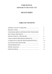
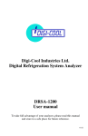
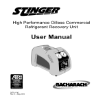
YELLOW JACKET ® ACCUPROBE™ UV and ACCUPROBE™ II Refrigerant Leak Detector with Heated Sensor Instruction and Operation Manual Models 69336, 69337, 69338, 69339 and 69354 Design Certified to meet SAE J2791 for R-134a Made in U.S.A. Introduction The YELLOW JACKET® ACCUPROBE™ UV and ACCUPROBE™ II Hand-held Leak Detectors detect all HCFC refrigerants such as R-22 and R-124. The ultra-sensitive long life sensor with exclusive Heated Electrochemical Sensor Technology (HES) also detects the more current, difficult-to-detect HFC refrigerants such as R-134a, R-404A, R-407C and R-410A (see page 6 for a more complete chart of detectable refrigerants). The ACCUPROBE UV is equipped with the unique digital SmartAlarm™ LED display – the first digital leak size indicator in a hand-held heated sensor leak detector. This Advanced digital SmartAlarm™ leak size The ACCUPROBE UV also features a 3 LED UV light system that works with 395-415nm wavelength leak tracing dyes. The sleek, ergonomic design of these YELLOW JACKET leak detectors makes them easy to use in close areas and extendable into hard-to-reach areas. Automatic calibration and reset to ambient Features feature takes the guesswork out of whether or not to repair a small leak. Unlike the more traditional LED bar graphs that copy or mimic the audio alarm signal, the SmartAlarm digital leak size indicator measures, registers and displays the leak size independently from both the audio alarm and the sensitivity level. indicator (AccuProbe UV) Flashing visual alarm indicator at probe end (AccuProbe UV) Audio mute button (AccuProbe UV) Operates on 4 AA alkaline batteries (AccuProbe UV can also use AC power) 3 LED UV light system that works with 395-415nm wavelength leak tracing dyes (AccuProbe UV) Microcontroller technology Ultra-high sensitivity to detect 0.06 oz (1.7g)/yr. of R-134a and 0.03 oz (0.9g)/yr. of R-22 Detects HFC, HCFC and CFC refrigerants (see page 6) Long life stable sensor utilizing Heated Electrochemical Sensor (HES) technology 3 selectable sensitivity level settings Sleek ergonomic design Low battery indicator Temp Range 24° to 125°F (-4° to + 52°C) Humidity 0 to 95% RH noncondensing SAE J2791Certified CE Marked True mechanical pump Specifications Sensitivity 0.06 oz (1.7g)/yr. of R-134a 0.03 oz (0.9g)/yr. of R-22 Power 4 AA alkaline batteries Probe Length 17 inches (430mm) Calibration Automatic Sensor Life >300 hours Length(body) 10.5 inches (270mm) Weight AccuProbe II - 15 ounces (430g); AccuProbe UV - 17 ounces (480g) Battery Life 4.5 hours continuous Response Time Instantaneous 2 Parts and Controls UV LEDs Alarm speaker Low battery indicator Digital SmartAlarm™ Sensitivity level indicators UV LED Power ON/OFF Sensitivity adjust/select Power ON/OFF Audio mute Heated sensor Flashing LED A/C adapter jack Flexible probe AccuProbe UV Tip AccuProbe UV AccuProbe II Battery Installation AccuProbe UV 1. Loosen battery door screw located on the bottom of the detector and remove door. 2. Install 4 AA alkaline batteries observing the proper battery polarity as labeled inside the battery compartment and shown above. 3. Reinstall the battery door and tighten the screw. AccuProbe II 1. Loosen screw located at rear end of unit and pull down hinged battery door to open as shown. 2. Always insert all four batteries with the proper polarity. 3 Operating Instructions AccuProbe UV 1. POWER ON: The detector is turned ON and OFF by pressing the POWER button (see figure 1 below). 2. WARM-UP: The detector automatically starts heating the sensor to condition it for use. While in this WARM UP phase – and until ready – the instrument will signal audibly by beeping slowly and visually by flashing the sensitivity LEDs and the zero (0) in the SmartAlarm™ display window. Warm up time is usually about 20 SECONDS or less. 3. SEARCH: The detector is ready for leak searching when the sensitivity LEDs stop flashing and the beep rate increases. At this time the zero in the display window stops flashing. When a leak is detected, the beeping sound and flashing LED in the probe will increase in frequency, and the SmartAlarm digital LED display will turn on indicating the leak size. If no leak is detected go to HI sensitivity and continue searching. SmartAlarm™ DISPLAY LEAK SIZE DISPLAY (OZ/YR.)* 1 TO 3 < 0.1 (2.8g) 4 TO 6 0.1 to 0.5 (2.8-14g) 7 TO 9 > 0.5 (14.1g) *HFC and HCFC Refrigerants The maximum value displayed, once the source of the leak is located, indicates the leak size. This value helps you decide whether or not a leak is large enough to require repair. The table above shows the leak rates corresponding to the SmartAlarm numerical display. UV LIGHT OPERATION CAUTION: EMITS ULTRAVIOLET RADIATION This UV LED during operation radiates UV light Avoid direct eye and skin exposure to UV light If viewing the UV light is necessary, please use UV filtered glasses to avoid damage by the UV light SmartAlarm™ Display The SmartAlarm LED Display is a digital leak size indicator that numerically displays the leak size on a scale of 1 to 9 for all HFC and HCFC refrigerants – regardless of the sensitivity setting. This value helps you decide whether or not the leak is large enough Before leak checking with the UV light: to require repair. (a) Make sure the A/C system is properly charged For example, when in the HI sensitivity mode, the with sufficient dye (see manufacturer’s specifidetector may sound a full audio alarm but the Smarcations for proper dye charge.) tAlarm Display may show a low number – indicat(b) Run the A/C system long enough to thoroughly ing that the leak is very small. In contrast, when in mix and circulate the dye with the refrigerant the LO sensitivity mode, a full audio alarm may not and lubricating oil. sound but the SmartAlarm may show a high number, indicating that the leak is large. Low battery indicator UV LED Power ON/OFF Audio mute 4 Figure 1 Sensitivity level indicators Sensitivity adjust Power ON/OFF 1. Turn on UV light by pressing the UV light ON/OFF button (see diagram on left). 2. Holding the leak detector approximately 10” to 14” away, shine the UV light beam slowly over the components, hoses, and metal lines that make up the A/C system. 3. When the UV light shines on the fluorescent dye that has escaped from the system, the dye will glow a bright yellow green. 4. The UV LEDs will automatically turn off after five minutes. 3 UV LED Lights Using the SmartAlarm Display 1. 2. Adjusting the sensitivity levels The SmartAlarm will not display a num- To choose another sensitivity level, press the ber (1 through 9) until a leak is sensed. Sensitivity button. The LED below each level Once a leak is sensed, the numbers on the will change indicating the new setting. display will gradually increase. The leak detector will default to the NORM Use the SmartAlarm display to "zero in" sensitivity level automatically once the unit on the leak source by watching the num- comes out of the warm-up cycle and the green bers climb higher as the leak source is LED turns on. approached. 3. Once the leak source has been located, always wait for the maximum number to be displayed to determine the size of the leak. 4. Lower numbers (approximately 1 to 3) indicate that the leak size is less than 0.1 oz/yr. and may not require repairing at this time – depending on the amount of gas in system. NOTE: Multiple small leaks in a system are cumulative and may require that all system leaks should be repaired. Using the Leak Standard Use the leak standard to determine that the leak detector performs to specifications. 1. Lift off the plastic sealing cap on the top of the LEAK STANDARD. 2. 1. TURN ON: Press the ON/OFF button once to turn on and again to turn off. POWER ON the unit. After WARM UP and when READY expose the sensor directly to the small hole in the top of the bottle cap. The beep rate should increase to an alarm. For the AccuProbe, the SmartAlarm should display a number greater than 2. If the SmartAlarm fails to display 2 or above, leave the detector on for approximately 15 to 30 seconds longer and retest. This indicates that the sensor and electronic circuit are functioning properly. 2. 3. WARM UP: The detector automatically starts heating the sensor. During the heating cycle, the detector will sound a slow “beep.” Warm up is generally less than 20 seconds. Replace plastic cap seal after leak test. Note: Replace the leak standard when the green color is no longer visible. 3. READY: The detector is ready to begin searching for leaks when the green sensitivity LED turns on. The audio “beep” increases in frequency. AccuProbe II Removable sealing cap Non-removable cap with leak opening Non-ozone depleting chemical has green color Leak Standard Bottle Sensitivity level indicators Power ON/OFF Sensitivity adjust AccuProbe II Keypad 5 Low battery indication Maintenance Replace the batteries when the red low battery LED comes on (see page 3). Follow instructions under section titled "BATTERY INSTALLATION" on page 3. Batteries: Replace the batteries when the Audio alarm mute (AccuProbe UV) Sensor filter replacement: Unscrew the sensor tip as shown to replace the filter. For optimum performance, replace filter whenever it becomes visibly dirty with grease or oil or every 2-3 months (depending on use). To silence the audio alarm, press the MUTE button. Press the MUTE button again to restore the audio alarm. Sensor failure mode If the sensor is not working correctly, the AccuProbe Leak Detector will not come out of the warm-up mode. (Some competitive units without this function will not alert you that the sensor is malfunctioning or has failed.) red low battery LED turns on. See “BATTERY INSTALLATION” on page 3. Note: Never clean dirty filters with a solvent or soap and water. Always replace with a new filter supplied with the leak detector or they can be re-ordered from your supplier or distributor. Sensor replacement: Remove sensor by pulling out of socket. Install the new sensor by If the AccuProbe detector does not come out aligning the notch in the sensor cover with the of warm-up, first be sure the sensor is plugged in all the way. If that does not correct the situa- raised keyway on the sensor socket holder (see Figure 2). tion, replace the sensor. Note: Do not force sensor into socket. Misalignment can damage the sensor pins. Push straight on (do not twist) to install sensor Unscrew tip to replace filter Filter Keyway alignment Pull straight out (do not twist) to remove sensor Figure 2 Partial list of detectable SNAP* listed refrigerants R-12 ALTERNATIVES R-22 ALTERNATIVES R-134a, R-401A (MP-39), R-401B (MP-66), R-401C (MP-52), R -406A (GHG) R-407C, R-410A, R-410B, R-507 R-414A (GHG-X4), R-414B (Hot Shot), R-416A (Frig C, FR-12) R-113, R-13B & R-503 ALTERNATIVES R-409A (FX-56), Freeze 12, Free Zone, GHG-X5, GHG-HP, IKON 12 R-403B, R-508A, R-508B R-502, R-500 ALTERNATIVES HC REFRIGERANTS (not SNAP approved) R-402A&B, R-404A, R-407A, R-408A, R-411A&B, R-507 R-290, R-600A, R-170/R-290, R-600A/R-290 * SNAP (Significant New Alternatives Program) an EPA program for ozone depleting refrigerants for mobile and stationary A/C systems 6 Replacement Parts AccuProbe UV and AccuProbe II Parts kit (sensor, filters and leak standard bottle) 69383 Sensor and filter 69384 Sensor filters (package of 5) 69385 Leak standard bottle 69386 A/C Adapter Input: 115V 60Hz AccuProbe UV AccuProbe II UL listed 69380 A/C Adapter—EU/UK Plug Input: 230V 50Hz CE & TÜV Approved 69381 A/C Adapter—AU/NZ Plug Input: 230V 50Hz CE & TÜV Approved 69378 Battery cover and screw 69388 Carrying case - blow molded with inserts 69387 Carrying pouch 69361 Troubleshooting Guide PROBLEM CHECK REPAIR OR REPLACE No power Check for weak or reversed batteries Replace batteries Stays in "warm up" mode Sensor not plugged into socket correctly Sensor open/defective Make sure sensor is pushed all the way down into socket Replace sensor No detection Check sensor with leak standard Replace sensor bottle Check if the filter is dirty or sensor Replace filter or clean out opening opening is plugged Slow recovery after detection Check if filter is dirty or sensor opening is plugged Replace filter or clean out opening No beeping Nothing Press mute button (if equipped) to turn speaker back on Certified to the European Standard EN 14624 (Section 13) Minimum sensitivity R-134a fixed position 1 gram/year Maximum sensitivity R-134a fixed position >50 gram/year Minimum sensitivity R-134a in motion 3 gram/year Maximum sensitivity R-134a in motion >50 gram/year Minimum time for detection 1 gram/yr R-134a 1 second Zeroing time for 50 grams/yr exposure Approximately 12 seconds Minimum sensitivity in polluted ambience 1 gram/year fixed; 3 grams/year moving Calibration frequency Check annually with calibrated leak source 7 18 MONTH LIMITED WARRANTY Ritchie Engineering guarantees YELLOW JACKET AccuProbe Leak Detectors to be free of defective material and workmanship that would affect the life of the product under normal use for the purpose for which it was designed. This warranty does not cover items that have been altered, abused, misused, improperly maintained or returned solely in need of field service maintenance. This warranty excludes the sensor, which is warranted for one year. If found defective, we will upon compliance with the following instructions, credit, replace or repair at our option, the defective leak detector provided it is returned within 18 months of the date of sale. ACCUPROBE leak detectors have a date of manufacture serial number located on the label on the bottom of the unit. Correction in the manner provided above shall constitute a fulfillment of all liabilities with respect to the quality, material and workmanship of the product. THE FOREGOING WARRANTY IS EXCLUSIVE AND IN LIEU OF ALL OTHER WARRANTIES OF QUALITY, WHETHER WRITTEN, ORAL OR IMPLIED. Cross Sensitivity to Automotive Chemicals Some automotive solvents and chemicals have similar hydrocarbon properties as R-134a and may elicit a positive response (<30 seconds) from the AccuProbe. Before leak checking, clean up any chemicals in the list below that elicit a positive response. Brand/Chemical Name Response Clears <30 seconds Dextron Transmission Fluid heated to 160° F N N/A Quaker State Motor Oil heated to 160° F N N/A Rain-X Windshield Wash Fluid N N/A Ford Silicone Lubricant N N/A Ford Rust Inhibitor (when wet) Y Yes Ford Gasket Adhesive (when wet) Y Yes Loctite Natural Blue Degreaser (undiluted) Y Yes Ford Brake Parts Cleaner (when wet) Y Yes Ford Silicon Rubber (when uncured) Y Yes Motorcraft Antifreeze heated to 160° F Y Yes Gunk Liquid Wrench (when wet) Y Yes Ford Spot Remover (when wet) Y Yes Ford Pumice Lotion (with mineral solvent) Y Yes Ford Motorcraft Brake Fluid Y Yes Ford Carburetor Cleaner (when wet) Y Yes For tips on searching for leaks, visit www.yellowjacket.com Copyright © 2006-2010 YELLOW JACKET Products Division Ritchie Engineering Co., Inc. 10950 Hampshire Avenue South Bloomington, MN 55438-2623 Telephone: 800-769-8370 or 952-943-1333 Fax: 800-322-8684 or 952-943-1605 E-mail: [email protected] Web: www.yellowjacket.com Printed in U.S.A. P/N 400399_Rev.A