1
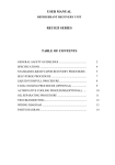
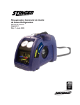
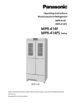
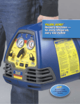
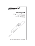
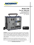
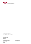
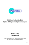
High Performance Oilless Commercial Refrigerant Recovery Unit User Manual 2079-1130 Rev. 6 – May 2010 Introduction Congratulations on your purchase of the STINGER high performance oilless recovery unit. Bacharach has worked hard to make the STINGER the highest performing, most portable, and easiest to use recovery unit on the market. We are committed to your complete satisfaction! CAUTION: These instructions are for personnel trained and experienced in the handling of refrigerants. Unqualified individuals should not attempt to operate this equipment. Failure to follow proper operating procedures may cause personal injury. WARNING: Inhalation of high concentrations of refrigerant vapors is harmful and may cause heart irregularities, unconsciousness, or death. Deliberate inhalation of refrigerants is extremely dangerous and death can occur without warning. Vapors reduce oxygen available for breathing and are heavier than air. Decomposition products are hazardous. Liquid contact may cause frostbite. All refrigerant containers, equipment, and hoses are under pressure. CAUTION! Before operating this unit, please read this manual in its entirety. It is important that you have a thorough understanding of the procedures outlined in this manual. Failure to follow these procedures could void all manufacturer warranties. WARNING! This unit is capable of over-pressurizing a DOT recovery cylinder. Ensure that you are using the proper DOT recovery cylinder for the refrigerant that you are recovering. NOTE: R-410 is capable of pressures exceeding 600 psi. Typical DOT recovery cylinders are rated at 350 psi with a pressure relief set at 550 psi. These cylinders should not be used with R-410A. Only cylinders rated at 400 psi with the relief valve setting at 600 psi should be used to for R-410A. Failure to use the proper cylinder can be extremely dangerous! BEFORE handling refrigerants, read the material safety data sheet from the refrigerant manufacturer 2 STINGER Specifications STINGER Compatible Refrigerants R-12, R-22, R-114, R-134a, R-401A, R-401B, R-401C, R-402A, R-402B, R-404A, R-406A, R-407A, R-407B, R-407C, R-407D, R-408A, R-409A, R-410A, R-411A, R-411B, R-412A, R-500, R-502, R-507, R-509 Power • 110/120 VAC, 1 Phase, 50/60 Hz, 8 Amps • 220 VAC, 1 Phase, 50/60 Hz, 4 Amps Compressor ¾ HP High Performance Oilless Cooling Two Cooling Fans Protection High pressure cutoff at 550 psi. Compressor is protected by circuit breakers and internal compressor thermal sensor. Optional 80% tank full shutoff kit (P/N 2090-0091). Pressure Ratings Low Side design pressure 450 PSI High Side design pressure 550 PSI Temperature Operating Range 32 to 104 °F (10 to 40 °C) Case Blow-Molded, High Impact Polyethylene Size / Weight Length 17" Width 9.5" Height 11" Weight 24 Lbs. Certification See label on back of unit Complies with UL1963 (not evaluated for automotive use) Refrigerant Recovery Rates Certified per ARI 740-95 & 740-98 Refrigerant Liquid Rate Liquid Push-Pull Rate Vapor Rate Vacuum Level (inches Hg) R-22 3.53 lb/min 1.60 kg/min 12.30 lb/min 5.58 kg/min 0.29 lb/min 0.13 kg/min >15 2.67 lb/min 1.21 kg/min 3.02 lb/min 1.37 kg/min 10.98 lb/min 4.98 kg/min 14.62 lb/min 6.63 kg/min 0.22 lb/min 0.10 kg/min 0.22 lb/min 0.10 kg/min R-134A R-410A 3 >15 >15 Table of Contents Introduction............................................................................................. 2 STINGER Specifications ........................................................................ 3 Table of Contents ................................................................................... 4 General Safety ....................................................................................... 5 Operational Safety.................................................................................. 6 Description of Features .......................................................................... 7 Vapor/Liquid Recovery Operations......................................................... 9 Standard Recovery Hose Connections................................................. 10 Liquid Push-Pull Recovery Operations ................................................. 11 Liquid-Pull Recovery / Charging Method .............................................. 13 R-410A Recovery – Special Notes ....................................................... 14 Purging the STINGER .......................................................................... 15 DOT Recovery Cylinder Safety ............................................................ 16 Recovery Tips ...................................................................................... 17 Troubleshooting.................................................................................... 18 Schematic Diagrams ............................................................................ 19 STINGER Parts List ............................................................................. 20 STINGER Exploded View ..................................................................... 21 Compressor Parts List .......................................................................... 22 Compressor Exploded View ................................................................. 23 Warranty / Repair Procedures .............................................................. 24 4 General Safety Know your equipment Read and understand the User Manual and labels affixed to the unit. Learn the application and limitations as well as the specific potential hazards of your equipment. Ground all equipment This unit is equipped with a three-pronged grounded power cord. Use the proper extension cord Keep extension cord length to a minimum. Use the following guide for choosing the proper extension cord: 18 gauge cord – maximum length 10 feet 16 gauge cord – maximum length 25 feet 14 gauge cord – maximum length 50 feet 12 gauge cord – maximum length 100 feet Use approved hoses Use refrigerant connection hoses that are approved to SAE J2196-1992. These hoses must provide a shut-off device within 12 inches of the ends, and must be approved for outdoor usage. Use approved recovery tank Use a DOT approved refrigerant recovery tank made for use with the type of refrigerant being recovered. Note that R-410 is capable of pressures exceeding 600 psi. Typical DOT recovery cylinders are rated at 350 psi with a pressure relief set at 550 psi. These cylinders should not be used with R-410A. Only cylinders rated at 400 psi with the relief valve setting at 600 psi should be used to for R-410A. Failure to use the proper cylinder can be extremely dangerous! Use weight scale A scale must be used to indicate when the recovery tank is 80% full when the STINGER does not have the 80% Shutoff Kit option installed. Avoid dangerous environments Although the unit can be used outdoors, we do not recommend operation in the rain, or in wet locations. Secure the unit when working above floor level. This equipment should not be used in the vicinity of spilled or open containers of flammable materials. Ventilation requirements This equipment should be used in a location with mechanical ventilation that provides at least 4 air changes per hour, or the equipment should be located at least 18" above the floor. Use recommended accessories Follow the instructions that accompany all accessories. Improper use of accessories may damage the equipment or create a hazard. Repair damaged parts Do not operate the unit with a defective part. Repair unit to proper operating conditions. 5 Operational Safety WARNING: Inhalation of high concentrations of refrigerant vapors is harmful and may cause heart irregularities, unconsciousness, or death. Deliberate inhalation of refrigerants is extremely dangerous and may cause death. Vapor reduces the oxygen available for breathing and is heavier than air. Decomposition products are hazardous. Liquid contact can cause frostbite. All refrigerant containers, equipment, and hoses are under high pressure. • • • • • • • • • • Avoid breathing high concentrations of vapors. Use with sufficient ventilation to keep operator exposure below recommended limits, especially in enclosed and low lying areas. Avoid contact of liquid with eyes and prolonged skin exposure. Wear safety goggles and protective gloves. Make sure the power switch is in the OFF position before plugging this equipment into an AC power source. Unplug unit before servicing; otherwise, an electrical shock hazard will be present when the unit is disassembled. Use caution when connecting or disconnecting hoses. Improper usage may result in refrigerant burns (frostbite). If a significant refrigerant leak occurs, proceed immediately to a well-ventilated area. Do not apply open flame or heat unit above 125 °F. Do not allow refrigerants to contact open flame. Decomposition will occur. Inhalation of decomposition is harmful. First Aid: Breathing: If high concentrations of refrigerant vapors are inhaled, immediately remove the person(s) to fresh air. Keep calm. If not breathing, give artificial respiration. If breathing is difficult, give oxygen. Call a doctor. Do not give epinephrine or similar drugs. Eye: In case of liquid contact, immediately flush eye with water. Seek medical attention. Skin: Flush with water. Treat for frostbite by gently warming the affected area. CAUTION: All refrigerant hoses, recovery tanks, refrigerant lines, the STINGER unit, and other vessels containing refrigerants should be handled at all times as if under high pressure. 6 Description of Features 1. Inlet Gauge Displays the inlet/suction pressure of the system being evacuated. 2. Purge Valve This valve determines what function the STINGER performs. This valve is UP during recovery operations and DOWN for purging and liquid push-pull operations. 3. Inlet Port Valve Opens or closes the inlet port. Points UP (open) for all recovery operations and points DOWN for purging operations. 4. Inlet Port Refrigerant hose connection for incoming refrigerant. 5. Outlet Gauge Displays the outlet/discharge pressure. 6. Outlet Port Valve Opens or closes the outlet port. Points UP when it is open, and to the left when CLOSED. 7. Outlet Port Refrigerant hose connection for outgoing refrigerant. 8. Circuit Breakers Protects the STINGER from over current. 9. 80% Tank Full Shutoff Cord (Optional) This optional accessory connects to a DOT recovery cylinder’s overfill sensor and automatically shuts the STINGER off when the recovery cylinder reaches 80% of its liquid-fill limit. Note: If this option is installed, the STINGER will not operate unless it is connected to a recovery cylinder with a compatible level-float switch. If the recovery cylinder does not have a float switch, then a shorting cap must be installed on the shutoff cord. 10. Power Cord Plugs into an appropriate AC outlet. Note that 220 VAC units are equipped with a male IEC 60320 plug that requires a customer supplied power-cord adapter that conforms to local electrical codes. 11. Power Switch When in the ON position, this switch starts the recovery operation by turning ON the compressor. 12. Storage Pocket This heavy-duty storage pocket is used to store the Operations Manual, the Warranty Card and the Original Invoice. These items should be kept with the unit at all times. 7 Description of Features Continued 1. Inlet Gauge 5. Outlet Gauge 2. Purge Valve 3. Inlet Port Valve 6. Outlet Port Valve 7. Outlet Port 4. Inlet Port 8. Circuit Breakers 11. Power Switch 9. Location of optional 80% tank full shutoff cord 12. Storage Pocket 10. Power Cord (Note: 220 VAC units have a male IEC 60320 type plug that requires the use of a customer supplied power-cord adapter) 8 Vapor/Liquid Recovery Operations Perform the following steps when recovering refrigerant that is either in vapor or liquid form. Note: Refer to “R-410A Recovery – Special Notes” on Page 14 when recovering R-410A. 1. Turn off all electrical or mechanical power to the refrigerant device to be evacuated. 2. Make proper hose connections. Connect refrigerant hoses to recovery cylinder, STINGER, and A/C system as shown on Page 10. When possible, use a manifoldgauge set to recover refrigerant from both the high- and low-side service ports. This will speed up the recovery rates. CAUTION: If the 80% tank full shutoff cord is not used, then use a scale to monitor the refrigerant level in the recovery cylinder in order to prevent overfilling. CAUTION: When recovering R-410A, you must use a recovery cylinder approved for use with R-410A. Standard recovery cylinders with 350 psi working pressures are not approved for use with R-410A. 3. Turn the inlet and outlet valves to their “OPEN” position, and the PURGE valve to its “RECOVER” position. Open the vapor valve on the DOT recovery tank. 4. Use the rear mounted power switch to turn ON the STINGER. The compressor will now begin to recover refrigerant. Note: When recovering liquid, in rare instances a “knocking” sound may come from the compressor. This indicates that too much liquid is entering the compressor. The inlet valve must be regulated (closed) until this knocking sound stops, otherwise compressor damage could occur. Pumping liquid when the compressor is knocking will damage the compressor, reduce the compressor life, and void the compressor’s warranty. This condition is rare and should not occur under normal recovery operations. 5. 6. Proceed with the recovery process until the system pressure shows a vacuum. Turn OFF the STINGER for a minimum of 5 minutes; after which, determine the amount of refrigerant remaining in the system. Repeat this step until system pressure is below mandatory EPA levels. Purge the STINGER as follows: a. Turn OFF the STINGER. b. Turn the inlet and purge valves to their “PURGE” position (both pointing DOWN), and the outlet valve to its “OPEN” position (pointing UP). c. Turn ON the STINGER and monitor the inlet gauge. The purge operation is complete when the inlet pressure gauge shows a vacuum. 9 Standard Recovery Hose Connections IMPORTANT NOTES FOR LIQUID RECOVERY Do not pump virgin refrigerant with the STINGER. Unlike recovered refrigerant, virgin refrigerant does not contain oil. Pumping virgin refrigerant through the STINGER will remove all lubrication from the compressor bearings, resulting in premature bearing failure. Use the liquid push-pull method or the liquid-pull method to transfer large amounts of liquid refrigerant (virgin or dirty). Attention: You must use an agency approved in-line filter when recovering liquid. Contaminants (particularly from the bottom of recovery cylinders) can enter the STINGER and become lodged in the valve seats causing damage and resulting in leaks. We recommend using Bacharach in-line filter P/N 0007-1700 to guarantee optimum pumping speed. 10 Liquid Push-Pull Recovery Operations Attention: Before attempting liquid push-pull recovery operations, please review this page. A scale or liquid-sight glass can be used to determine when all the liquid is recovered. The STINGER will not pull a vacuum using the liquid push-pull recovery operation. To finish the recovery operation, you must perform vapor recovery operations as described on Page 9. GUIDLINES: If any of the following conditions are present in the system being evacuated, the liquid pushpull operations may not be practical and vapor recovery operations should be performed. The equipment contains less than 20 lbs of refrigerant. The equipment is a heat pump or other system with refrigerant flow that would prevent you from isolating the liquid. Equipment has an accumulator between the service ports used in the liquid recovery process. Liquid refrigerant migration has occurred and the location of the liquid is unknown. The refrigerant tubing design on the equipment does not allow for a solid column of liquid refrigerant to be formed. STEPS: The liquid push-pull recovery method requires the use of a third hose. In addition, a sightglass is useful for determining when all of the liquid has been pushed out of the system. After all the liquid has been pushed out, you will need to reconfigure the hoses for vapor recovery since the liquid push-pull recovery method does not pull a vacuum on the system. 1. Remove power from the refrigerant device to be evacuated. 2. Make proper hose connections for liquid push-pull recovery as shown in the diagram on Page 12. CAUTION: If the 80% tank full shutoff cord is not used, then use a scale to monitor the refrigerant level in the recovery cylinder in order to prevent overfilling. CAUTION: When recovering R-410A, you must use a recovery cylinder approved for use with R-410A. Standard recovery cylinders with 350 psi working pressures are not approved for use with R-410A. 3. Turn the inlet and outlet valves to their “OPEN” position and the PURGE valve to its “PURGE” position. Note: The “PURGE” position bypasses the condenser, optimizing the push-pull flow rate. 11 Liquid Push-Pull Operations Continued 4. Open both the vapor and liquid valves on the DOT recovery tank. 5. Turn ON the STINGER. The compressor will begin to “pull” vapors from the cylinder and “push” the liquid out of the system and into the recovery cylinder. 6. If a sight-glass is being used, you should watch it to determine when all of the liquid has been removed from the system. 7. The liquid push-pull recovery method will not pull a vacuum in the system. You must turn OFF the STINGER and reconfigure the hoses for vapor recovery operations as described on Page 9. 12 Liquid-Pull Recovery / Charging Method Do not pump virgin refrigerant with the STINGER. Unlike recovered refrigerant, virgin refrigerant does not contain oil. Pumping virgin refrigerant through the STINGER will remove all lubrication from the compressor bearings, resulting in premature bearing failure. Use the liquid push-pull method or the liquid-pull method to transfer large amounts of liquid refrigerant (virgin or dirty). The liquid-pull method is used to move a large amount of liquid refrigerant without the refrigerant passing directly through the STINGER. The virgin refrigerant is pulled directly into the system being charged. The STINGER keeps the pressure low in the system by removing vapor. For every pound of vapor removed, as much as 25 pounds of liquid refrigerant may be transferred. This method can be used for either virgin refrigerant or really dirty refrigerant. 13 R-410A Recovery – Special Notes R-410A is a replacement refrigerant for R-22. Its physical properties, however, are much different than R-22. R-410A has a higher vapor pressure and is more dense than R-22. These characteristics make recovering R-410A more difficult by putting more of a load on the compressor. Please follow the instructions below to ensure trouble-free R-410A recovery. Note: Hose connections are the same for recovering R-410A. Connect hoses as shown in the vapor recovery diagram below. Under normal operating conditions the STINGER can recover R-410A just like R-22. Under certain conditions, however, because of R-410A’s higher vapor pressure and density, you will have to take the following precautions: CAUTION: USE ONLY DOT RECOVERY CYLINDERS APPROVED FOR USE WITH R-410A. Overfilling or over-pressurizing your recovery cylinder is extremely dangerous! WHEN RECOVERING VAPOR: If the STINGER sounds like it is overloaded either by slowing down or by making a “knocking” sound, reduce the inlet pressure by closing or “throttling” the inlet valve until the STINGER begins to run normally. WHEN RECOVERING LIQUID: If a loud knocking noise occurs, the inlet pressure on the STINGER should be throttled back by slowly closing the inlet valve until the knocking noise stops. This action will prevent compressor damage. 14 Purging the STINGER The STINGER is equipped with a pump-down purge valve that allows the technician to pump down or evacuate the STINGER before proceeding to the next recovery operation. This procedure not only eliminates cross contamination, but also conserves refrigerant. Follow the steps below to ensure your pump-down operation is performed correctly. During the purge operation the entire STINGER is pulled into a vacuum, leaving no more than 0.1 ounce of refrigerant in the unit. STEPS: 1. After recovery operations are complete, and with the unit still powered ON and running, make the following control valve position changes (refer to illustration below): • Turn the inlet valve (blue knob left side) slowly to the “PURGE” position (pointer DOWN position). • Turn the purge valve (black knob center) slowly to the “PURGE” position (pointer DOWN position). 2. The STINGER will now start purging itself of refrigerant. Allow the unit to run until the inlet gauge indicates that there is an adequate vacuum present in the system. 3. Turn OFF the STINGER and then turn the outlet valve (red knob right side) to its “CLOSED” position. 4. Close the Vapor and Liquid valves on the DOT recovery tank. 5. Remove all hoses. 15 DOT Recovery Cylinder Safety WARNING! This unit is capable of over-pressurizing a DOT recovery cylinder. Ensure that you are using the proper DOT recovery cylinder for the refrigerant that you are recovering. R-410A is capable of pressures exceeding 600 psi. Typical DOT recovery cylinders are rated at 350 psi with a pressure relief set at 550 psi. These cylinders should not be used with R-410A! Only cylinders rated at 400 psi with a pressure relief set at 600 psi should be used to recover R-410A. Failure to use the proper cylinder can be extremely dangerous. If your STINGER is equipped with the optional 80% tank full shutoff cord, connect this cord to a DOT recovery cylinder’s float switch. This cord connection will automatically shut OFF the STINGER when the recovery cylinder reaches 80% of its liquid-full limit. It is recommended that you use this cord for added safety. If your STINGER is not equipped with an 80% tank full shutoff cord, or if you are using a recovery cylinder that does not have a float switch, then you must use a scale to prevent overfilling the cylinder. Note: If the 80% tank full shutoff cord is present, but not being used, then a shorting cap must be installed on the shutoff cord in order for the STINGER to operate. Bacharach uses and recommends the Air Conditioning & Refrigeration Institute's (ARI) Guideline K for the safe filling and handling of used refrigerant. This Publication is available from ARI at http://www.ari.org. The following information provides the safe fill weights for used refrigerant based on the size of the container and is in accordance with Guideline K: WATER CAPACITY NET REFRIGERANT WEIGHT GROSS CONTAINER WEIGHT (APPROX.) 30 lbs 50 lbs 95 lbs 145 lbs 238 lbs 24 lbs 40 lbs 76 lbs 98 lbs 190 lbs 38 lbs 59 lbs 118 lbs 153 lbs 274 lbs 16 Recovery Tips • Use the shortest hoses possible. Long hoses increase the recovery time. Remove all restrictions in the hoses. Hoses with ball valves on the ends are better than hoses that are self-sealing. Remove Schrader core valves when possible from service ports. • Always identify the refrigerant you are recovering. This will minimize cross contamination and help you plan for the amount of refrigerant you will be recovering. • Always pump liquid out of the system first, and then recover the remaining vapors. This will significantly speed up recovery rates. • With large amounts of refrigerant, use the liquid push-pull recovery method. This method is three times faster than recovering liquid directly. Refer to the liquid push-pull instructions on Page 11. • When possible, recover from both the high and low side service port on the refrigeration system. This will speed up the recovery rate. • Use an agency approved in-line filter (P/N 0007-1700) to prevent contaminants from entering the STINGER. • If the STINGER has the optional 80% tank full shutoff cord installed, connect this cord to the recovery cylinder’s float switch. If the cylinder does not have a float switch, then be sure to install a shorting cap on the shutoff cord; otherwise, the STINGER will not operate. Note: Although using a manifold gauge set will speed up the recovery process, a manifold gauge set is not required. 17 Troubleshooting PROBLEM CAUSE ACTION Unit will not start – Fan does not run; compressor does not start Power Cord not attached Attach Power Cord No voltage at receptacle Verify voltage at job site Unit will not start – Fan starts and runs; compressor starts but will not stay on Optional 80% tank full shutoff cord not connected to tank Connect cord Float switch in tank is open Check tank switch with multimeter Tank is full and float switch has opened Change tanks or short cord and use scale Circuit breaker has opened Identify cause of breaker activation, rectify and reset Discharge pressure too high Reduce pressure and rotate Purge Valve to “Purge” and back to “Recover” HP Switch has opened Reduce pressure Electronics failure in motor, or on printed circuit board Factory service required Purge valve is in “Purge” position during recovery and HP switch activates Rotate Purge Valve to “Recover” Discharge valve is not open and HP switch activates Rotate Discharge Valve to “Open” position Recovery tank valve not open Open tank valve Blocked discharge hose Check and clear blockage Air in system/tank Bleed air from system/tank Compressor stops intermittently Vapor pressure of refrigerant in tank is close to HP trip point Reduce tank temperature Unit overheats Excessive suction pressure due to high ambient temperature Reduce inlet pressure below 80 psi by throttling the inlet valve. Recovery process too slow Head pressure too high Reduce tank temperature or change tanks System refrigerant iced up Throttle gauge manifold valves and discharge valve to reduce pressure differential between LP and HP gauges Cooling fan runs but compressor will not start Compressor starts but cuts out within a few minutes; pressure indication on HP gauge is high Interrupt process and allow ice to dissipate Restriction in hoses or manifold gauge set Check and clear restriction Compressor seals are worn Rebuild compressor – check with wholesaler for assistance 18 Schematic Diagrams 19 STINGER Parts List See STINGER Exploded View on Page 21. Item No. Part Number 1 2045-0620 Compressor (110/120 VAC) 1 1 2045-0720 Compressor (220 VAC) 1 2 2023-0100 Manifold 1 3 2014-0310 High Pressure Switch, 550 psi 1 4 2013-0090 Fan, 4", 110/120 VAC 1 4 2013-0040 Fan, 4", 220 VAC 1 5 2043-0140 Plastic Case, Left 1 6 2043-0150 Plastic Case, Right 1 7 2063-0150 Gauge, Low Pressure 1 8 2063-0160 Gauge, High Pressure 1 9 2015-0140 Printed Circuit Board (110/120 VAC) 1 9 2015-0160 Printed Circuit Board (220 VAC) 1 10 2043-0160 Screen Guard, Condenser 1 11 2043-0130 Screen Guard, Fan 1 12 2014-0030 Circuit Breaker, 10 amp 2 13 2013-0055 Compressor Fan Blade 1 14 2043-0170 Vinyl Storage Pouch 1 15 2090-0059 Power Switch 1 16 2043-0120 Plastic Knob, Outlet, Red 1 17 2043-0100 Plastic Knob, Inlet, Blue 1 18 2043-0110 Plastic Knob, Black 1 19 2051-0660 Plastic Caps w/ Retainer 3/8" 2 20 2051-1680 Screws For Knobs 3 21 2022-0030 Fitting, Cylinder Head Elbow 2 -- 2079-1130 Instruction Manual -- 2090-0091 80% Tank Full Shutoff Kit Description Qty 1 20 (Optional) STINGER Exploded View 21 Compressor Parts List See Compressor Exploded View on Page 23. Part No. Item Description Qty 2081-0410 1 Motor Shaft Head Bearing 1 2081-0370 2043-0030 2 3 Crank Housing Shaft Seal 1 1 2051-1900 2081-0310 4 5 Screw, Machine, M5 x 10MM Piston Cup Seal Retainer 1 1 2043-0020 2081-0270 6 7 Piston Cup Seal Piston 1 1 2081-0400 2081-0260 8 9 Piston Journal Bearing Crank 1 1 2077-0940 2081-0300 10 11 Gasket Crank Housing End Cover 1 1 2051-1920 2081-0390 12 *13 Screw, Cap, M5 x 18MM Shim, 0.002" 4 1 2081-0420 2081-0430 *14 *15 Shim, 0.003" Shim, 0.005" 1 1 2077-0950 2081-0290 16 17 O-Ring, #026 Cylinder 1 1 2090-0039 2081-0280 18 19 Valve Plate Assembly Cylinder Head 1 1 2051-1910 2090-0040 20 21 Screw, Cap, M5 x 50MM Motor Brushes 4 2 2090-0041 22 2 2090-0042 -- Cap, Motor Brush Compressor Rebuild Kit Includes Items 4, 5, 6, 13, 14, 15, 16, 18 *Any or all of these shims may be used. 22 1 Compressor Exploded View 23 Warranty / Repair Procedures Bacharach warrants this product for 1 year from the date of purchase indicated on the original sales receipt. The warranty covers all parts within the unit but excludes damage to the unit caused by misuse or mishandling. The unit’s motor brushes carry an extended warranty of 5 years. If the unit is in need of warranty service within 90 days of its date of purchase, it will be replaced with a brand new one via our over the counter (OTC) exchange program. To obtain a warranty replacement unit via the OTC exchange program, the following steps must be followed: 1) Return the unit to the wholesaler that it was purchased from, along with proof of purchase (original or copy of sales receipt). 2) If the wholesaler determines the unit is eligible for OTC exchange, it will be replaced with a brand new one. 3) The wholesaler should then contact our Customer Service Department for a return goods authorization (RGA) in order to return the defective unit and have an order entered for its replacement. Proof of purchase will be required in order to process the RGA. OTC exchange units are processed as no charge orders. If the unit is outside the 90 day OTC exchange period but within the 1 year warranty period, the following steps must be followed: 1) Download and fill out our Service Request Form at http://www.mybacharach.com/service.htm. If Internet access is not available, contact our Customer Service Department at 800-736-4666. They will fax you a copy of the form. 2) Return the unit, freight prepaid, along with proof of purchase (original or copy of sales receipt) to: Bacharach, Inc. 621 Hunt Valley Circle New Kensington, PA 15068 3) Upon receipt the unit will be evaluated. If the failure is determined to have been caused by a factory defect, it will either be repaired or replaced with a new or like new unit at Bacharach’s discretion. If the failure is determined to have been caused by customer misuse or mishandling or proper proof of purchase has not been supplied, an estimate of the repair costs will be provided before any repairs or modifications are made to the unit. If you have any questions, please contact our Customer Service Department at 800-7364666 or email them at [email protected]. 24