1
NetGuardian-16S
USER MANUAL
Visit our website at www.dpstelecom.com for the latest PDF manual and FAQs.
December 8, 2006
D-OC-UM06C.08103
Firmware Version 1.0
Revision History
December 8, 2006
NetGuardian-16S User Manual (D-OC-UM06C.08103) released.
Supports Firmware Version 1.0.
October 2, 2006
NetGuardian-16S User Manual (D-OC-UM06A.02102) released.
Supports Firmware Version 1.0.
November 8, 2005
NetGuardian-16S User Manual (D-OC-UM05B.08101) released.
Supports Firmware Version 1.0.
This document contains proprietary information which is protected by copyright. All rights are reserved. No part of this
document may be photocopied without prior written consent of DPS Telecom.
All software and manuals are copyrighted by DPS Telecom. Said software and manuals may not be reproduced, copied,
transmitted or used to make a derivative work, by either mechanical, electronic or any other means in whole or in part,
without prior written consent from DPS Telecom, except as required by United States copyright laws.
© 2005 DPS Telecom
Notice
The material in this manual is for information purposes and is subject to change without notice. DPS Telecom shall not be
liable for errors contained herein or consequential damages in connection with the furnishing, performance, or use of this
manual.
Contents
Visit our website at www.dpstelecom.com for the latest PDF manual and FAQs
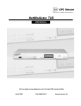
1 NetGuardian-16S Overview
1
2 Shipping List
2
3 Optional Accessories
3
4 Specifications
4
5 Installation
5
5.1 Tools Needed
5
5.2 Mounting
5
5.3 Power Connection
6
5.4 LAN Connection
7
5.5 Telco Connection
7
5.6 Alarm and Control Relay Connections
8
5.6.1
Alarm and Control Relay Connector Pinout Table
8
5.6.2
Discretes 1–24 Connector Pinout Diagram
9
5.6.3
Discretes 25–32/Relays 1–8 Connector Pinout Diagram
10
5.7 Data Ports
11
5.8 NetGuardian Expansion Port
11
5.9 Craft Ports
12
5.10 Jumper Options — Switch Control Relays from Normally Open to Normally Closed
13
6 Building Status Unit
14
6.1 Standard Mode
14
6.2 Standalone Mode
15
7 Voice Call Out
7.1 Voice Call Out Sequence of Operations
8 LCD Display
15
16
17
8.1 Alarm and Control Status Messages
17
8.2 LCD Command Menu
18
8.2.1
Sound off
18
8.2.2
Reboot
19
8.2.3
Run Config
19
8.2.4
Contrast
20
9 Alarm Speaker
20
10 Front Panel LEDs
21
11 Back Panel LEDs
22
12 Connecting to the NetGuardian via Craft Port
23
13 TTY Interface
24
13.1 Menu Shortcut Keys
25
13.2 Unit Configuration
25
13.2.1 Ethernet Port Setup
25
13.2.2 Edit PPP Port
27
13.3 Monitoring
13.3.1 Monitoring the NetGuardian
28
28
13.3.1.1 Monitoring Base Alarms
13.3.1.2 Monitoring Ping Targets
28
13.3.1.3 Monitoring and Operating Relays (Controls)
13.3.1.4 Monitoring System Alarms
30
13.3.1.5 Monitoring Data Port Activity
31
29
30
13.3.2 Viewing Live Target Pings
32
13.3.3 Proxy Menu
33
13.3.4 Event Logging
34
13.3.5 Backing Up NetGuardian Configuration Data via FTP
34
13.3.5.1 Reloading NetGuardian Configuration Data
13.3.6 Debug Input and Filter Options
14 Web Browser Interface
36
37
38
14.1 Logging On to the Web Browser Interface
38
14.2 Logging Out of the Web Browser Interface
39
14.3 Other Top Frame Links
39
14.4 Monitor and Edit Menus
40
14.5 Monitor Menu
41
14.5.1 Alarm Summary
41
14.5.2 Base Alarms
42
14.5.3 Ping Targets
42
14.5.4 System Alarms
43
14.5.5 Controls
44
14.5.6 Event Log
45
14.5.7 Port Transmit and Port Receive
46
14.6 Edit Menu
47
14.6.1 Call List
47
14.6.2 Date and Time
49
14.6.3 Reboot
49
14.6.4 NVRam
50
15 Reference Section
51
15.1 NetGuardian-16S Alarm Map
51
15.2 System Alarm Descriptions
52
15.3 Voice Call Out Default Dialogs
53
15.3.1 Dialog 1: Default Critical
53
15.3.2 Dialog 2: Default Major
53
15.3.3 Dialog 3: Default Secure Dial-In
54
15.3.4 Dialog 4: Critical GR-474
54
15.3.5 Dialog 5: Major GR-474
55
15.3.6 Dialog 6: GR-474 Secure Dial-In
55
15.3.7 Dialog 7: Critical RUS-FORM-522
56
15.3.8 Dialog 8: Major RUS-FORM-522
56
15.3.9 Dialog 9: RUS-FORM-522 Secure Dial-In
57
15.4 NetGuardian-16S Trap OIDs
58
15.5 SNMP Granular Trap Packets
59
15.6 ASCII Symbol Descriptions
60
15.7 Modem Access
61
16 Technical Support
62
1
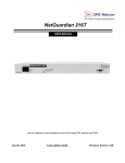
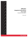
1 NetGuardian-16S Overview
Fig. 1.1. NetGuardian-16S: High capacity and versatile capabilities make it a powerhouse RTU
NetGuardian-16S — Proven Hardware and Software, New and Expanded Capabilities
The NetGuardian-16S is a multifunction, high capacity, NEBS-certified, LAN-based, SNMP/DCPx remote
telemetry unit. The NetGuardian-16S is based on the proven hardware and software capabilities of DPS
Telecom's popular NetGuardian-16S 832A RTU, but the NetGuardian-16S adds greatly expanded functionality.
The NetGuardian-16S incorporates many functions that previously required several separate units, while
occupying only 1 RU on any standard 19" or 23" equipment rack, freeing valuable rack space for
revenue-generating equipment.
The NetGuardian-16S features:
· Built-in Web Interface: monitor your alarms from any computer, without an alarm master
· Two separate IP addresses for security: one IP address for private company LAN access, and a second IP
address for public Internet access
· Voice Call Out for reporting alarms via telephone call
· Integrated Building Status Unit for local alarm visibility
· 32 reversible discrete alarm inputs (expandable to 176 alarm points by adding NetGuardian-16S DX
Expansion Units)
· 16 reach-through serial ports with terminal server functionality for connecting multiple concurrent
users via Telnet over LAN to telecom switches, servers, radios, PBXs and other equipment
· 8 programmable NO/NC control relays (expandable to 32 by adding NetGuardian-16S DX Expansion
Units)
· 32 ping alarms
· Automatic 24/7 email and pager alarm notification
· Alarm reporting to any SNMP manager or the T/Mon NOC Alarm Monitoring System
· Backup dial-up alarm reporting
· Dual –48 VDC power inputs
· Free lifetime firmware updates, installed via LAN or serial connection
· NEBS Level 3 compliance
Dual IP address security model for safe public access
For enhanced security, the NetGuardian-16S has two separate IP addresses on separate subnets. This allows you
to safely connect the NetGuardian-16S to both your private company LAN and the public Internet. Since the
public IP address is on a separate subnet, users from the outside cannot connect to your company LAN.
Connect via LAN to telecom switches, servers, radios and more
The NetGuardian-16S's 16 reach-through serial ports provide LAN-based terminal server access to up to 16 serial
devices Multiple users can simultaneously connect to the NetGuardian-16S via Telnet over LAN to connect and
control telecom switches, servers, radios, multiplexers, PBXs and many other types of remote site equipment.
NEBS-compliant for guaranteed reliability
The NetGuardian-16S is compliant with NEBS Level 3 electrical, environmental and safety standards.
NEBS-certified NetGuardian-16S models are available as an option.
2
2 Shipping List
Please make sure all of the following items are included with your NetGuardian-16S. If parts are missing, or if
you ever need to order new parts, please refer to the part numbers listed and call DPS Telecom at
1-800-622-3314.
NetGuardian-16S
D-PK-NETGD-12001
NetGuardian-16S User Manual
D-OC-UM06C.08103
NetGuardian-16S Resource CD
(includes manuals, MIBs, and software)
DB9M-DB9F Download Cable 6 ft.
D-PR-045-10-A-04
Two Ethernet Cables 14 ft.
D-PR-923-10A-14
Telephone Cable 6 ft.
D-PR-045-10A-01
23" Rack Ears
19" Rack Ears
Eight 3/8" Ear Screws
Four Standard Rack Screws
3
Four Metric Rack Screws
Two 3/4-Amp GMT Fuse
Two Power Connector Plugs
Pads
3 Optional Accessories
Extend the capabilities of your NetGuardian-16S with these optional hardware accessories. To order or for more
information, call DPS Telecom at 1-800-622-3314.
NetGuardian Expansion (NetGuardian DX G4)
D-PK-NETDX-12022.00001
The NetGuardian Expansion G4 provides an additional 48 discrete and 8 analog alarm points. Up to three
NetGuardian Expansions can be daisy-chained off one NetGuardian-16S, providing a total of 176 discrete and 32
analog alarm points.
Building Status Unit (BSU)
D-PK-BSU02-12001
The Building Status Unit provides auxiliary local enunciation of alarms. The BSU features a single large
visual indicator for local alerts. Alarms may be acknowledged locally on the BSU, which will in turn
acknowledge the alarm in the NetGuardian-16S. Sound level of the audible speaker can be adjusted with
the volume control.
4
4 Specifications
Discrete Alarm Inputs:
32 (reversible; expandable to 80, 138 or 176 alarm points)
Control Relays:
8 Form C (expandable to 16, 24 or 32 control relays)
Maximum Voltage:
60 VDC/120 VAC
Maximum Current:
1 Amp, AC/DC
Protocols:
SNMP
DCPx, (T/Mon NOC reporting)
Interfaces:
16 RJ45 RS-232 reach-through serial ports (1200 to 115,200 baud)
2 50-pin connectors (discrete alarm inputs and control relay outputs)
2 RJ45 10BaseT Ethernet ports
1 RJ45 NetGuardian-16S Expansion port
1 RJ11 telco jack
2 DB9 front panel craft ports
Dimensions:
1.75" H x 8" W x 6" D (4.5 cm x 20.3 cm x 15.2 cm)
Mounting:
19" or 23" rack
Power Inputs:
Dual –48 VDC (–40 to –70 VDC)
Current Draw:
200 mA (350 mA at power up)
Fuse:
3/4 Amp GMT
Modem:
33.6K internal
Visual Interface:
LCD display
3 Critical-Major-Minor alarm status lights
30 bicolor LEDs
7 unicolor LEDs
Audible Notification:
Alarm speaker
Unit Controls:
4 LCD menu control buttons
Operating Temperature:
32°–140° F (0°–60° C)
Operating Humidity:
0%–95% noncondensing
5
5 Installation
5.1 Tools Needed
To install the NetGuardian-16S, you'll need the following tools:
Phillips No. 2 Screwdriver
Small Standard No. 2 Screwdriver
PC with Edit16S software
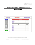
5.2 Mounting
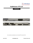
Fig. 5.2.1. The NetGuardian-16S can be flush or rear-mounted
The NetGuardian-16S mounts in a 19" rack or a 23" rack using the provided rack ears for each size. Two rack ear
locations are provided. Attach the appropriate rack ears in the flush-mount or rear-mount locations shown in
Figure 5.2.1.
Note: Rack ears can be rotated 90° for wall mounting or 180º for other mounting options (not shown).
6
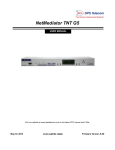
5.3 Power Connection
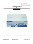
Fig. 5.3.1. Power connectors and fuse.
The NetGuardian-16S has two screw terminal barrier plug power connectors, located on the left side of the back
panel. (See Figure 5.3.1.)
Before you connect a power supply to the NetGuardian-16S, test the voltage of your power supply:
·
Connect the black common lead of a voltmeter to the ground terminal of the battery, and connect the red
lead of the voltmeter to the battery's –48 VDC terminal. The voltmeter should read between –43 and –
53 VDC. If the reading is outside this range, test the power supply.
To connect the NetGuardian-16S to a power supply, follow these steps:
1. Remove the fuse from the back panel of the NetGuardian-16S. Do not reinsert the fuse until all
connections to the unit have been made.
2. Remove the power connector plug from Power Connector A. Note that the plug can be inserted into the
power connector only one way — this ensures that the barrier plug can only be reinserted with the
correct polarity. Note that the –48V terminal is on the left and the GND terminal is on the right.
3. Insert a battery ground into the power connector plug's right terminal and tighten the screw; then
insert a –48 VDC line to the plug's left terminal and tighten its screw.
4. Push the power connector plug firmly back into the power connector. If the power feed is connected
correctly, the LED by the connector will light GREEN. If the polarity of the power feed is reversed, the
LED by the power connector will light RED.
5. Repeat Steps 2–4 for Power Connector B.
6. Reinsert the fuse to power the NetGuardian-16S. The front panel LEDs will flash RED and GREEN.
7
5.4 LAN Connection
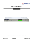
Fig. 5.4.1. Ethernet ports
For enhanced security, the NetGuardian-16S has two 10BaseT Ethernet ports. Each port has its own separate IP
address and subnet, so you can safely connect one port to your private company LAN and the other to the public
Internet.
Connect the Private Ethernet port to the company LAN.
Connect the Public Ethernet port to the Internet.
By default, outbound data traffic from the NetGuardian-16S will be sent over the Public Ethernet port. Only
outbound data that is specifically directed for the company LAN will be sent over the Private Ethernet port.
Both ports are standard RJ45 ports that take standard RJ45 Ethernet cables. If the IP connection is OK, the LNK
LED will light SOLID GREEN when the cable is connected.
RJ45 Ethernet Connection
8
7
6
5
4
3
2
1
Receive In– (RI–)
Receive In + (RI+)
Transmit Out– (TO–)
Transmit Out + (TO+)
Fig. 5.4.2 Ethernet port pinout
The pinout for the Ethernet ports is shown in Figure 5.4.2, above.
5.5 Telco Connection
Fig. 5.5.1. Telco jack
The rear panel telco jack (see Figure 5.5.1) connects the NetGuardian-16S internal modem to a standard phone
line for dial-up access and pager alarm notification.
8
5.6 Alarm and Control Relay Connections
Fig. 5.6.1. Alarm and control relay connectors
The NetGuardian-16S's discrete alarm inputs and control relay outputs are connected through the two 50-pin
connectors labeled "Discretes 1–24" and "Discretes 25–32/Relays 1–8" on the back panel. (See Figure 5.6.1.)
5.6.1 Alarm and Control Relay Connector Pinout Table
Discretes 1–25
RTN ALM
RTN ALM
ALM 1
1
26 ALM 13 13
38
ALM 2
2
27 ALM 14 14
39
ALM 3
3
28 ALM 15 15
40
ALM 4
4
29 ALM 16 16
41
ALM 5
5
30 ALM 17 17
42
ALM 6
6
31 ALM 18 18
43
ALM 7
7
32 ALM 19 19
44
ALM 8
8
33 ALM 20 20
45
ALM 9
9
34 ALM 21 21
46
ALM 10 10
35 ALM 22 22
47
ALM 11 11
36 ALM 23 23
48
ALM 12 12
37 ALM 24 24
49
GND
25
50
Discretes 25–32
RTN ALM
ALM 25
1
26
ALM 26
2
27
ALM 27
3
28
Control Relays 1–8
NO/NC CO
CTRL 1
9
34
CTRL 2
10
35
CTRL 3
11
36
ALM 28
ALM 29
4
5
29
30
CTRL 4
CTRL 5
12
13
37
38
ALM 30
6
31
ALM 31
7
32
CTRL 6
CTRL 7
14
15
39
40
ALM 32
8
33
CTRL 8
16
41
FUSE
17
42
GND
25
50
Table 5.6.1.A. Alarm and control relay connector pinout
Table 5.6.1.A, above, shows the pinouts for the 50-pin connectors "Discretes 1–24" and "Discretes 25–32/Relays
1–8."
Note that the NetGuardian-16S's control relays can be set for either Normally Open or Normally Closed
operation. By factory default, all control relays are set to Normally Open. You can reset all relays for Normally
Closed operation at the hardware level by resetting a jumper on the NetGuardian-16S circuit board.
For instructions on resetting control relays for Normally Closed operation, see Section 5.10, "Jumper Options —
Switch Control Relays from Normally Open to Normally Closed."
9
5.6.2 Discretes 1–24 Connector Pinout Diagram
RTN 1
RTN 2
RTN 3
RTN 4
RTN 5
RTN 6
RTN 7
RTN 8
RTN 9
RTN 10
RTN 11
RTN 12
RTN 13
RTN 14
RTN 15
RTN 16
RTN 17
RTN 18
RTN 19
RTN 20
RTN 21
RTN 22
RTN 23
RTN 24
GND
1
2
3
4
5
6
7
8
9
10
11
12
13
14
15
16
17
18
19
20
21
22
23
24
25
26
27
28
29
30
31
32
33
34
35
36
37
38
39
40
41
42
43
44
45
46
47
48
49
50
ALM 1
ALM 2
ALM 3
ALM 4
ALM 5
ALM 6
ALM 7
ALM 8
ALM 9
ALM 10
ALM 11
ALM 12
ALM 13
ALM 14
ALM 15
ALM 16
ALM 17
ALM 18
ALM 19
ALM 20
ALM 21
ALM 22
ALM 23
ALM 24
GND
Fig. 4.6.2.1. Pinout Diagram for Discretes 1–24 connector
10
5.6.3 Discretes 25–32/Relays 1–8 Connector Pinout Diagram
RTN 25
1
RTN 26
2
RTN 27
3
RTN 28
4
5
RTN 29
RTN 30
6
7
RTN 31
8
RTN 32
CTRL 1 NO 9
CTRL 2 NO 10
CTRL 3 NO 11
CTRL 4 NO 12
CTRL 5 NO 13
CTRL 6 NO 14
CTRL 7 NO 15
CTRL 8 NO 16
FUSE NO 17
Unused
18
19
Unused
Unused
20
21
Unused
Unused
22
Unused
23
24
Unused
25
GND
26
27
28
29
30
31
32
33
34
35
36
37
38
39
40
41
42
43
44
45
46
47
48
49
50
ALM 25
ALM 26
ALM 27
ALM 28
ALM 29
ALM 30
ALM 31
ALM 32
CTRL 1 CO
CTRL 2 CO
CTRL 3 CO
CTRL 4 CO
CTRL 5 CO
CTRL 6 CO
CTRL 7 CO
CTRL 8 CO
FUSE CO
Unused
Unused
Unused
Unused
Unused
Unused
Unused
GND
Fig. 4.6.3.1. Pinout Diagram for Discretes 25–32/Relays 1–8 connector
11
5.7 Data Ports
Fig. 5.7.1. Data ports 1–16
The NetGuardian-16S's 16 data ports provide reach-through terminal server functionality for connecting multiple
simultaneous users to external equipment via Telnet over LAN. Each port can function as a proxy connection to
an external device, a craft port, a channel port, a TCP or UDP reach-through port. The NetGuardian-16S can
support simultaneous proxy connections for up to five users.
RJ45 RS-232 Serial Port
8 RTS
7
6 TXD
5 GND
4 GND
3 RXD
2
1 CTS
Fig. 5.7.2 Data port pinout
The pinout for Data Ports 1–16 is shown in Figure 5.7.2, above.
5.8 NetGuardian Expansion Port
Fig. 5.8.1. NetGuardian-16S Expansion port
The EXP port (see Figure 5.8.1) connects the NetGuardian-16S to a NetGuardian-16S DX Expansion Unit. Up to
three NetGuardian-16S DX Expansion Units can be daisy-chained from the NetGuardian-16S. Each
NetGuardian-16S DX adds 48 discrete alarm points, or 48 discrete alarms and 8 control relays, to the
NetGuardian-16S, for configurations of:
·
1 NetGuardian-16S DX Expansion Unit: 80 discrete alarms and (optional) 16 control relays
·
2 NetGuardian-16S DX Expansion Units: 128 discrete alarms and (optional) 24 control relays
·
3 NetGuardian-16S DX Expansion Units: 176 discrete alarms and (optional) 32 control relays
To order NetGuardian-16S DX Expansion units, call DPS Telecom at 1-800-622-3314.
12
RJ45 RS-232 Serial Port
8 RTS
7
6 TXD
5 GND
4 GND
3 RXD
2
1 CTS
Fig. 5.8.2 NetGuardian-16S expansion port pinout
The pinout for the NetGuardian-16S expansion port is shown in Figure 5.8.2, above.
5.9 Craft Ports
Fig. 5.9.1. Craft ports
The NetGuardian-16S has two craft ports, one for each of the unit's two internal circuit boards.
The upper craft port is used for : 1) connecting a PC running the Edit16S configuration software via a COM port
connection; 2) accessing the NetGuardian-16S TTY configuration interface; and 3) loading firmware updates to
the upper circuit board.
The lower craft port is used for loading firmware updates to the lower circuit board.
13
5.10 Jumper Options — Switch Control Relays from Normally
Open to Normally Closed
Fig. 5.10.1. The control relay jumpers are accessible through a notch in the upper circuit board, on the front
right corner of the unit
Fig. 5.10.2. Detail view showing how the jumpers are labeled on the circuit board
By factory default, the NetGuardian-16S's eight control relays are configured for Normally Open operation. You
can reconfigure the control relays for Normally Closed operation by resetting jumpers on the NetGuardian-16S
circuit board. Each control relay can be individually reconfigured by setting the jumpers.
To open the unit and expose the circuit board, remove the screws from the top of the NetGuardian-16S and lift
the top cover off. The control relay jumpers are on the lower circuit board, on the front right of the unit. The
upper circuit board is cut to allow access to the adjustable jumpers, as shown in Figure 5.10.1, above. Each
jumper has a label etched on the circuit board that shows which control relay it corresponds to, as shown in
Figure 5.10.2.
Fig. 5.10.3. Jumper settings for configuring the control relays
To switch a control relay to Normally Closed operation, place its corresponding jumper in the closed position, as
shown in Figure 5.10.3.
14
6 Building Status Unit
Fig. 6.1. Integrated Building Status Unit alarm status lights, speaker and Ack/+ button
The NetGuardian-16S incorporates an integrated Building Status Unit (BSU) that provides local notification of
selected alarms. The Building Status Unit panel consists of the three Critical-Major-Minor lights on the right
front panel, plus the alarm speaker.
When an alarm occurs, the BSU alarm status lights will show the alarm's severity (see Figure 6.1, above), and the
alarm speaker will emit a continuous tone. To silence the speaker, press the Ack/+ button.
(Note: Audible alarms from the BSU cannot be silenced by the Sound off command on the LCD Command
Menu. For details on the Sound off command, see Section 8.2.1, "Sound off.")
The BSU operates in two modes: Standard Mode and Standalone Mode.
6.1 Standard Mode
In Standard Mode, the BSU is controlled by the CopperCom CopperController. The CopperController's
configuration determines which alarms will trigger a BSU notification. If a selected alarm occurs, the
CopperController will issue a Sound Alarm command to the BSU (and any external Building Status units
connected to the NetGuardian-16S). Pressing the Ack/+ button on the NetGuardian-16S or the Ack button on the
CopperController sends an acknowledgment signal to the CopperController, and the CopperController then sends
a Silence Alarm command to the BSU (and any external BSUs).
15
6.2 Standalone Mode
If the NetGuardian-16S loses its connection to the CopperController, the BSU will enter Standalone Mode. In
Standalone Mode, the NetGuardian-16S's internal configuration determines which alarms will trigger a BSU
notification. If a selected alarm occurs, the NetGuardian-16S will trigger the BSU alarm and send a Sound Alarm
command to any external BSUs. Pressing the Ack/+ will silence the alarm speaker directly, and send an Silence
Alarm command to any external BSUs.
The NetGuardian-16S determines whether to put the BSU in Standalone Mode by pinging the CopperController.
The NetGuardian-16S will put the BSU in Standalone Mode only if it does not receive a ping response from the
CopperController.
If the BSU enters Standalone Mode the BSU SM LED will light SOLID RED and the NetGuardian-16S will
declare a Critical alarm.
In Standalone Mode, the NetGuardian-16S determines which alarms will trigger a BSU notification, and the
alarm severity level of the BSU notification, by referring to which alarms have been assigned to Alarm Point
Groups 6, 7 and 8 by the system administrator.
Group 6 = BSU Critical
Group 7 = BSU Major
Group 8 = BSU Minor
Alarm Point Group assignments can only be configured by the system administrator. For more information on
Alarm Point Groups, see Section 12.5.1, "Alarm Summary."
7 Voice Call Out
The NetGuardian-16S features Voice Call Out, which provides alarm reporting via telephone call. The Voice
Call Out function will call up to 10 user-defined contact phone numbers to announce Critical and Major alarms
with up to 16 dialogs. For a reference to possible Voice Call Out dialogs, see Section 13.4, "Voice Call Out
Default Dialogs," in the Reference section.
Voice Call Out is controlled by the CopperCom CopperController in Standard Mode and by the
NetGuardian-16S in Standalone Mode.
Voice Call Out is available only for Critical and Major alarms. No Major alarm can be added to the Voice Call
Out queue until all Critical alarms are acknowledged. When a Critical alarm occurs, all pending Major alarms
will be removed from the Voice Call Out queue.
The contacts for Voice Call Out are defined in the user-configurable Call List. Each contact can be configured to
receive only Critical alarm calls, Major alarm calls, or both Critical and Major alarm calls. For instructions on
configuring the Call List, see Section 12.6.1, "Call List."
You can also dial in to the NetGuardian-16S and receive a voice update on current alarm status. For some
example dial-in dialogs, see Section 13.4, "Default Voice Call Out Dialogs," in the Reference section.
16
7.1 Voice Call Out Sequence of Operations
1.
In Standard Mode, Voice Call Out is initiated when the CopperCom CopperController sends an SNMP
SET command. In Standalone Mode, Voice Call Out is initiated when an alarm occurs that has been
assigned to Group 6 - BSU Critical or Group 7 - BSU Major by the system administrator.
2.
If the modem is busy with data traffic, Voice Call Out is paused until the modem is clear.
3.
If and when the modem is clear, Voice Call Out is paused for the Call Qual Time period set by the
system administrator.
4.
If the alarm that triggered Voice Call Out clears during the Call Qual Time, Voice Call Out will be
canceled. (If the alarm clears during the call, Voice Call Out will play the message "Alarm Cleared" and
hang up.)
5.
Critical call outs always supersede Major call outs. If a Major call out is in progress when a Critical
alarm occurs, the Major call out will be canceled. (If a Major call out is terminated during a call, the
NetGuardian-16S will play the message "Critical abort" and hang up.)
6.
When Voice Call Out is initiated, the NetGuardian-16S will dial the first number listed on the Call List
for the alarm's severity level.
7.
The NetGuardian-16S will play the dialog determined by the CopperController's SNMP SET command.
If the SET command does not specify an alarm dialog, the NetGuardian-16S will play the dialog
selected for this contact in the Call List.
8.
The dialog will be repeated up as many times as specified in the Repeat Count setting. There will be a
pause after each repetition to allow the user to enter the DTMF acknowledge code.
9.
The user can interrupt the dialog at any time by pressing the Star (*) key. The user can then enter the
DTMF Acknowledge Code.
10. If the user makes a mistake entering the acknowledge code, he or she can clear the entry by pressing the
Star (*) key.
11. If the user enters the correct code, the notification sequence will end.
12. If the call remains unacknowledged after a user-defined time period, the NetGuardian-16S will call the
next contact listed in the Call List.
13. If the alarm clears during the call, the NetGuardian-16S will play the message "Alarm Cleared" and
hang up. Critical clears will not cancel a Major call out, and Major clears will not cancel Critical call
outs. Major call outs (but NOT Critical call outs) can also be aborted by pressing the BSU Ack button.
14. The notification sequence will continue until the alarm is acknowledged or the NetGuardian-16S has
attempted to reach every contact on the Call List. A system alarm will be declared if no contact
successfully acknowledged the alarm.
17
8 LCD Display
Fig. 8.1. NetGuardian-16S LCD showing the Standard Prompt
The front panel LCD displays the current alarm and control status and provides a command menu for controlling
the NetGuardian-16S's basic functions.
Using the LCD command menu
The four buttons surrounding the front panel LCD are used to access the LCD Command Menu. To access the
menu, press the Menu button. To scroll the menu, use the Ack/+ and – buttons. To select a menu command, press
the Sel (Select) button.
Standard Prompt
When no Command Menu item is selected and no alarms or relays are active, the LCD displays the firmware
version and the standard prompt, Press MENU for front panel options.
Controlling Display Speed
The scroll speed can be temporarily increased by pressing and holding the + button while the message is active.
8.1 Alarm and Control Status Messages
If an alarm or control relay is active, the LCD will display the following messages to indicate alarm and control
status:
Discrete Alarms:
If there are any standing discrete alarms, the display will read "Discrete Alarms:",
followed by the user-defined descriptions of the standing alarm points.
Relays:
If there are any latched relays, the display will read "Relays:", followed by the
user-defined descriptions of the latched relays.
Ping Alarms:
If any ping targets have failed to respond within the specified time, the display will
read "Ping Alarms:", followed by the user-defined descriptions of the ping targets.
18
8.2 LCD Command Menu
Fig. 8.2.1. LCD display, showing the Standard Prompt
The LCD Command Menu provides commands for controlling some of the NetGuardian-16S's basic functions:
temporarily silencing the alarm speaker, rebooting the unit, and running the TTY configuration utility.
When no Command Menu item is selected and no alarms or relays are active, the LCD displays the firmware
version and the Standard Prompt, Press MENU for front panel options. (See Figure 8.2.1,
above.)
To access the Command Menu, press the Menu button.
8.2.1 Sound off
Fig. 8.2.1.1. Sound Off command
Sound off
The Sound off command suppresses sounds from the alarm speaker for a user-defined period of 10, 20, or 30
minutes. (Note: The Sound off command setting does not silence audible alarms from the integrated Building
Status Unit. For details on the integrated BSU, see Section 6, "Building Status Unit.")
To scroll to the next menu command, press the – button.
To change the Sound off setting, press Sel to select the command. The arrow cursor (>) will move to the right
of the colon (:) in Sound off: to indicate that the command submenu is selected. Press the Ack/+ and –
buttons to scroll through the Sound off time period options. Select 0 minutes to allow all sounds. When the time
period you want is displayed, press Sel to make your selection.
To exit the Command Menu without changing the Sound off setting, press Menu.
19
8.2.2 Reboot
Fig. 8.2.2.1. Reboot command
Reboot
The Reboot command reboots the NetGuardian-16S.
To scroll to the next menu command, press the – button.
To reboot the NetGuardian-16S, press Sel. The LCD will briefly display the message Rebooting ..., and
the normal boot sequence will begin.
To exit the Command Menu without rebooting, press Menu.
8.2.3 Run Config
Fig. 8.2.3.1. Run Config command
Run Config
The Run Config command forces the TTY configuration interface to run over the upper craft port at 9600 baud.
To scroll to the next menu command, press the – button.
To run the TTY configuration utility, press Sel.
To exit the Command Menu without running the TTY interface, press Menu.
20
8.2.4 Contrast
Fig. 8.2.4.1. Contrast command
Contrast
The Contrast command provides controls for adjusting the contrast of the LCD.
To scroll to the next menu command, press the – button.
To adjust the contrast, press Sel to select the command. The arrow cursor (>) will move to the right of the
colon (:) in Contrast: to indicate that the command submenu is selected. Press the Ack/+ or – button until
you're satisfied with the contrast setting, then press Sel to make your selection.
To exit the Command Menu and revert to the default contrast setting, press Menu.
9 Alarm Speaker
The NetGuardian-16S's alarm speaker emits distinctive tones for three different circumstances:
1. If the integrated Building Status Unit alarm sounds, the speaker will emit a continuous tone. If the
BSU is in Standard Mode, the sound will continue until the CopperCom CopperController issues a
Silence Alarm command. To request a Silence Alarm command, press the Ack/+ button. If the BSU is in
Standalone Mode, pressing the Ack/+ button will silence the speaker immediately.
2. If there is an Ethernet connection failure, the speaker will emit a high-low warbling tone. Press any
front panel button to silence the speaker.
3. If a "reportable" discrete alarm occurs (that is, an alarm that is configured to trigger an SNMP Trap
or pager notification), the speaker will emit an intermittent beep. Press any front panel button to silence
the speaker. If you do not silence the speaker, the beep will continue for a few seconds.. Silencing the
speaker will allow the next alarm, if any, to sound.
The Sound off command on the LCD Command Menu (see Section 8.2.1, "Sound off") will suppress sounds
from Ethernet connection failures and discrete alarms, but will not prevent BSU alarms from sounding.
21
10 Front Panel LEDs
Fig. 10.1. Front panel LEDs
The NetGuardian-16S's front panel LEDs indicate communication and alarm reporting status. LED status
messages are described below in Table 10.A.
LED
Status
Blink Green
Craft 1
Blink Red
Blink Green
Exp
Blink Red
Blink Green
Private
Blink Red
Blink Green
Public
Blink Red
Blink Green
Data Ports 1–16
Blink Red
Blink Green
Craft 2
Blink Red
Blink Green
ICom
Blink Red
Blink Green
Modem
Blink Red
Blink Green
Config
Blink Red
Blink Red
Alarm
Solid Red
Solid Red
BSU SM
Off
Blink Green
DTMF
Blink Red
Solid Green
Voice
Off
Description
Transmit over upper craft port
Receive over upper craft port
Transmit to NetGuardian-16S Expansion
Receive from NetGuardian-16S Expansion
Transmit over Private Ethernet connection
Receive over Private Ethernet connection
Transmit over Public Ethernet connection
Receive over Public Ethernet connection
Transmit over indicated data port
Receive over indicated data port
Transmit over lower craft port
Receive over lower craft port
Lower board transmit to upper board
Upper board transmit to lower board
Transmit over modem
Receive over modem
Valid configuration
Invalid configuration
New COS alarm
One or more standing alarms
BSU Standalone Mode active
BSU Standalone Mode disabled
DTMF tone transmit for Voice Call Out
Receiving DTMF tones from Voice Call Out user’s phone
Voice Call Out voice playback active
Voice Call Out voice playback off
Table 10.A. Front panel LED Status message descriptions
22
11 Back Panel LEDs
Fig. 11.1. Back panel LEDs for Power (left) and Ethernet connections
The back panel LEDs indicate the status of power and Ethernet connections. LED status messages are described
below in Table 11.A.
LED
Status
Solid Green
Power A
Solid Red
Power
Solid Green
Power B
Solid Red
FA
Solid Red
Status Blink Green
Ethernet
LAN
Blink Green
LNK
Solid Green
Description
Correct polarity on power feed A
Reversed polarity on power feed A
Correct polarity on power feed B
Reversed polarity on power feed B
Fuse failure
Bus activity between LAN chip and processor
Transmit and receive activity
Ethernet link OK
Table 11.A. Back panel LED Status message descriptions
23
12 Connecting to the NetGuardian via Craft Port
Fig. 12.1.1. NetGuardian-16S's Top Craft Port
The simplest way to connect to the NetGuardian-16S is over a physical cable connection between your PC's
COM port and the NetGuardian-16S top craft port.
Note: You must be connected via the top craft port to use the TTY interface, but you don't have to be connected
to a NetGuardian-16S unit to use Edit16S. You only need a connection to the unit to read or write configuration
files to its NVRAM. You can use Edit16S on an unconnected PC to create and store NetGuardian-16S
configuration files.
Use the DB9M-DB9F download cable provided with your NetGuardian-16S to make the top craft port
connection.
Select the following COM port options:
• Bits per second: 9600
• Data bits: 8
• Parity: None
• Stop bits: 1
• Flow control: None
When a connection is established (sometimes accompanied by receipt of a hex byte), type DPSCFG, then press
Enter to activate the configuration menu.
You can perform all configuration tasks via the craft port — but if you like, you can connect via the craft port
just to configure the NetGuardian-16S's Private LAN IP address, and then do the rest of your configuration via a
LAN connection.xt here.
24
13 TTY Interface
Fig. 13.1. The TTY interface initial configuration screen
The TTY interface is the NetGuardian-16S's built-in controller for basic configuration and monitoring of the
NetGuardian-16S. Configure the NetGuardian-16S's ethernet port settings, monitor the status of base and system
alarms, operate control relays, view live ping targets , view debug or create proxy connections to other ports. For
more advanced configuration tools, please use the Edit16S utility.
To use the TTY interface with the NetGuardian-16S, all you need is any PC with terminal emulation software
(i.e. Hyperterminal) and a connection to the NetGuardian-16S. This connection can be a direct connection to the
NetGuardian-16S's top front panel craft port or a remote connection via Telnet or dial-up.
Some initial software configuration must be performed before you can use a remote connection to the
NetGuardian-16S. For Telnet, connect to the Net Guardian's IP address at port 2002 to access the configuration
menus after initial LAN/WAN setup. Telnet sessions are established at port 2002, not the standard Telnet
port as an added security measure.
The TTY interface is primarily used for configuring and provisioning the NetGuardian-16S, but you can also use
it to ping IP targets, view system statistics, and data port activity.
NOTE: The TTY default password is "dpstelecom".
If you have physical access to the NetGuardian-16S, the easiest thing to do is connect to the unit serially
through the top craft port and then assign it an IP address. Then you can complete the rest of the unit
configuration over a remote LAN connection, if you want. For instructions, see Section 12, "Connecting to the
NetGuardian-16S via Craft Port."
If you DON'T have physical access to the NetGuardian-16S, you can make a LAN connection to the unit by
temporarily changing your PC's IP address and subnet mask to match the NetGuardian-16S's factory default IP
settings. Follow these steps:
1. Look up your PC's current IP address and subnet mask, and write this information down.
2. Reset your PC's IP address to 192.168.1.200.
25
3. Reset your PC's subnet mask to 255.255.0.0. You may have to reboot your PC to apply your changes.
4. Once the IP address and subnet mask of your computer coincide with the NetGuardian's, you can access
the NetGuardian-16S via a Telnet session or via Web browser by using the NetGuardian-16S's default IP
address of 192.168.1.100.
5. Provision the NetGuardian-16S with the appropriate information, then change your computer's IP address
and subnet mask back to their original settings.
13.1 Menu Shortcut Keys
The letters before or enclosed in parentheses ( ) are menu shortcut keys. Press the shortcut key to access that
option. Pressing the ESC key will always bring you back to the previous level. Entries are not case sensitive.
13.2 Unit Configuration
13.2.1 Ethernet Port Setup
The NetGuardian-16S must be assigned an IP address before you will be able to connect via LAN/WAN using a
Telnet client or a Web browser. To connect via LAN, the minimum configuration requires setup of the IP address
and subnet mask. Minimum WAN configuration requires that the default gateway be set as well. Follow the
instructions below to configure the NetGuardian-16S's IP address, subnet mask and default gateway.
26
Fig. 13.2. Configure the Ethernet port parameters
1. Once a connection is established, the NetGuardian-16S will respond with "Password."
2. Type the default password, "dpstelecom," then press Enter.
Note: DPS strongly recommends changing the default password.
3. The NetGuardian-16S's main menu will appear.
4. Type C for the C)onfig menu.
5. Type E for E)dit menu.
6. Type E for port settings.
7. Type R for Private settings, or type U for Public settings.
8. Configure the unit address, subnet mask, and default gateway.
9. ESC to the main menu.
10. When asked if you would like to save changes, type Y (yes).
11. Reboot to save the new configuration to the NetGuardian-16S.
12. Now you can connect to the NetGuardian-16S via LAN and complete the configuration.
27
13.2.2 Edit PPP Port
Choose P)PP to edit your PPP port in TTY Interface. You can choose a baud rate, depending on what device has
been chosen for the PPP port.
Fig. 13.2.2.1 Edit your PPP port
If you are using a modem for the PPP port, then choose mo(D)em for the modem option to define the modem
initialization strings (see Figure 10.4).
Choose B)aud to define the baud rate for that port. (See Figure 13.2.2.2.)
Fig. 13.2.2.2. Select the baud rate for your PPP port
28
13.3 Monitoring
13.3.1 Monitoring the NetGuardian
Connect a PC running VT100 terminal emulation software to the craft port or connect via LAN using a Telnet
client with VT100 emulation to port 2002 to reach the monitor menu selection. This section allows you to do full
system monitoring of the NetGuardian-16S including: all alarms, ping information, relays, analogs, and system
status.
Fig. 13.3.1.1. The monitor menu allows status checking on all elements
13.3.1.1 Monitoring Base Alarms
View the status of the device connected to the discrete alarms from the M)onitor menu > A)larms option. Under
Status, the word Alarm will appear if an alarm has been activated and Clear will appear if an alarm
condition is not present. If groups are used the user defined status will be displayed.
Fig. 13.3.1.1.1. This example shows page two of the discrete alarms
29
13.3.1.2 Monitoring Ping Targets
View the status of all your ping targets from the M)onitor menu > P)ing targets option. This screen displays the
ping target ID, description, and IP address. Under Status the word Alarm will appear if an alarm has been
activated and Clear will appear if an alarm condition is not present.
Fig. 13.3.1.2.1. The Ping info submenu allows you to change ping targets
30
13.3.1.3 Monitoring and Operating Relays (Controls)
The NetGuardian-16S comes equipped with 8 relays that can be used to control external devices. Monitor the
status of your relays from the M)onitor menu > R)elays option.
Relays are set to normally open (N/O) as the factory default, but each or all of them can be changed to normally
closed (N/C) by changing their respective jumper (see Section 6.12, "Jumper Options").
Fig. 13.3.1.3.1 The eight relays can be operated from this screen
Caution: Relays are normally controlled by the Coppercom Controller
13.3.1.4 Monitoring System Alarms
View the status of the NetGuardian-16S's system alarms from the M)onitor menu > S)ystem option. Under
Status, the word Alarm will appear if an alarm has been activated and Clear will appear if an alarm
condition is not present. See Appendix, "System Alarm Descriptions," for more information. If groups are used
the user defined status will be displayed.
31
Fig. 13.3.1.5.1. System Alarms can be viewed from the M)onitor menu > S)ystem option
13.3.1.5 Monitoring Data Port Activity
View the status of the NetGuardian-16S's 16 data ports from the M)onitor menu > p(O)rts option. Enter the
number of the port you wish to view and press Enter.
The NetGuardian-16S provides an ASCII description under Transmit and Receive. Choose a) Transmit to
view data transmitted to another device. Choose b) Receive to view data received from another device. See
Appendix, "ASCII Conversion," for specific ASCII symbol conversion.
32
Fig. 13.3.1.6.1. Data port activity can be viewed from the M)onitor menu > p(O)rts option
13.3.2 Viewing Live Target Pings
Choose P)ing to ping any of the NetGuardian-16S's user defined IP addresses. Then enter the ID number (1-32)
of the IP address or enter any IP address to ping.
Fig. 13.3.2.1. Continuously ping an IP address that has been defined in the NetGuardian-16S's ping table
33
13.3.3 Proxy Menu
You can create proxy connections to reach-through to the craft port, modem port or any of the other eight serial
ports from the P)roxy menu. You'll be able to monitor and control additional devices via proxy connection to the
NetGuardian-16S. Data presented and handshaking will be specified by the connected device.
To cancel the proxy connection wait a half second, then quickly type @@@ and press ENTER.
Fig. 13.3.3.1. Access devices connected to the eight data ports on the back panel through M)onitor menu >
P)roxy option
Note: An issue has been identified when you attempt to access a IPM's PTMC (and modify PTMC parameters)
via the NetGuardian-16S which prevents these PTMC parameters from being changed. To avoid this from
happening, the terminal program must be configured to send CR+LF for "new-lines". Depending on the terminal
software in use, the actual configuration steps may vary but the steps identified for Tera Term Pro are:
Under "Setup" select "Terminal" and set "New-line", "Transmit:" to "CR+LF".
Please make a note of this when accessing PTMC configurations via the NetGuardian-16S (newer installations).
Also note that this configuration change should only be used when accessing the PTMC console function. When
accessing other console ports, keep the standard CR only configuration.
34
13.3.4 Event Logging
Choose E)vent log to view the up to 100 events posted to the NetGuardian-16S; including power up, base and
system alarms, ping alarms, analog alarms, and controls. Posted events for the various alarms include both alarm
and clear status. Refer to Table 13.3.4.A for event log field descriptions.
Note: All information in the event log will be erased upon reboot or a power failure.
Fig. 13.3.4.1. Monitor the last 100 events recorded by the NetGuardian-16S from the M)onitor menu > E)vent
log option
Event Log Field
Evt
Date
Time
Grp
State
PRef
Description
Description
Event number (1–100)
Date the event occurred
Time the event occurred
Alarm Group
State of the event (A=alarm, C=clear)
Point reference (See Appendix A for display descriptions).
User defined description of the event as entered in the alarm point
and relay description fields.
Table 13.3.4.A. Event Log field descriptions
13.3.5 Backing Up NetGuardian Configuration Data via FTP
1. From the Start menu on your PC, select RUN.
2. Type "ftp" followed by the IP address of the NetGuardian-16S you are backing up (e.g. ftp
126.10.120.199).
35
3. After the connection is made press Enter.
4. Enter the password of the NetGuardian-16S (default password is dpstelecom), then press Enter.
5. Type "binary" and press Enter (necessary for NetGuardian-16S file transfer).
6. Type "lcd" and press Enter (this allows you to change the directory of your local machine).
7. Type "get" followed by the name you wish to define for the NetGuardian-16S backup file. Add the
extension ".ngd" to the file name (e.g. get ngdbkup.ngd) and press Enter.
8. After reloading, type "bye" and press Enter to exit.
Note: The backup file name can have a maximum of eight characters before the file extension.
36
13.3.5.1 Reloading NetGuardian Configuration Data
1. From the Start menu on your PC, select RUN.
2. Type "ftp" followed by the IP address of the NetGuardian-16S you are backing up (e.g. ftp
126.10.120.199).
3. After the connection is made press Enter.
4. Enter the password of the NetGuardian-16S (default password is dpstelecom), then press ENTER.
5. Type "binary" and press Enter (necessary for NetGuardian-16S file transfer).
6. Type "lcd" and press Enter (this allows you to change the directory of your local machine).
7. Type "put" followed by the name you defined for the NetGuardian-16S backup file and press Enter (e.g.
put ngdbkup.ngd).
8. Type "literal REBT" to reboot the NetGuardian-16S.
9. After reloading, type "bye" and press Enter to exit.
37
13.3.6 Debug Input and Filter Options
Debug Input Options
ESC
B
T
U
R
X
?
Exit Debug
Show BAC status points
Show task status
Show DUART information
Show network routing table
Clear debug enable bitmap. Turn all debug filters OFF
Display Options
Debug Filter Options:
a
A
c
C
d
D
e
E
f
F
G
h
H
i
k
l
L
m
M
(1) Alarm toggle switch. Shows posting of alarm data
(2) Analog toggle switch. Shows TTY interface debug
(3) Config toggle switch. Shows TTY interface debug
(4) Control relay toggle switch. Shows relay operation
(5) DCP responder toggle switch. Shows DCP protocol
(6) Device toggle switch. Shows telnet, proxy information and Edit16S serial communication.
(7) Expansion poller toggle switch. Shows NGDdx polling
(8) ECU Interrogator toggle switch. Shows BAC processing
(9) FTP Command toggle switch. Shows command string parsing
(10) FTP Data toggle switch. Shows FTP Read / Write
(11) GLD poller toggle switch. Shows GLD polling
(12) HTML debug switch. Shows Web Browser processing
(13) HWACS debug switch. Shows hardware access operation
(14) PING toggle switch
(15) Socket toggle switch. Shows current dcu resources
(16) LED toggle switch. Shows current LED state
(17) LCD display toggle switch. Shows LCD control and text
(18) Modem toggle switch. Shows modem vectored initialization
(19) Undefined
o
(20) Osstart toggle switch. Miscellaneous application debug, including NVRAM read and write
operation, and event posting
O
p
P
q
Q
r
(21) Undefined
(22) SPORT toggle switch. Port init debug and channeled port debug
(23) PPP toggle switch. Shows PPP functioning
(24) QAccess toggle switch. Reserved for future use
(25) Undefined
(26) Report toggle switch. Shows reporting event activity, including SNMP, pagers, email, etc. Also
s
(27) SNMP toggle switch. Reserved for future use
S
(28) STAK toggle switch. Shows network processing and IPA of arp requests. Also shows packets
discarded by Filter IPA.
t
(29) TERM toggle switch. Shows UDP/TCP port handling. The camera and network time (NTP)
jobs also use the TERM toggle switch
V
w
W
shows PPP negotiation for NG client PPP mode.
(30) Undefined
(31) HTTP toggle switch. Shows handling of web browser packets
(32) WEB toggle switch 2. Dump HTML text from web browser
Table. 13.3.A. Debut Input and Filter Options
38
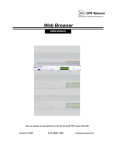
14 Web Browser Interface
Fig 14.1. The NetGuardian-16S Web Browser Interface
The NetGuardian-16S's Web Browser Interface lets you connect to the unit and view alarms from any computer.
Using the Web Browser Interface, you can view alarms, operate controls, and provision user-configurable
settings.
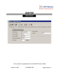
14.1 Logging On to the Web Browser Interface
Fig. 14.1.1. NetGuardian-16S Web Browser logon
To log on to the Web Browser Interface, enter the NetGuardian-16S unit's IP address in the address bar of your
Web browser. When you first connect to the NetGuardian-16S, you will see the logon page shown in Figure
12.1.1, above. Enter your password and click submit.
Your system administrator should have already assigned the NetGuardian-16S an IP address and a logon
39
password. If you do not know the IP address and password for your NetGuardian-16S unit, check with your
system administrator.
No more than four users can simultaneously log on to the Web Browser Interface. Each user session is tracked by
IP address, and the NetGuardian-16S will automatically log out users after 12 minutes of inactivity, unless the
system administrator has configured a different timeout duration.
14.2 Logging Out of the Web Browser Interface
Fig. 14.2.1. Web Browser interface Logout link
To log out of a Web Browser Interface session, click the Logout link in the top frame of your Web browser. The
Logout link is always available while you're using the Web Browser Interface. It's a good idea to log out before
closing your browser window. Exiting the Web Browser Interface without logging out can deny other users
access to the Edit menu. (See Section 12.3, "Monitor and Edit Menus," for more information.)
14.3 Other Top Frame Links
The top frame of the Web Browser Interface has three other links that are always available:
Refresh: Refreshes the browser window.
Upgrade: Opens a new browser window containing the firmware upgrade download page on the DPS Telecom
website.
Help: Opens a new browser window containing Web-based help for the NetGuardian-16S Web Browser
Interface.
40
14.4 Monitor and Edit Menus
Fig. 14.3.1. Monitor and Edit menus
After logging on, you will see the Alarm Summary page shown in Figure 12.1 on page 24. Note the Monitor and
Edit menus in the left frame of your browser. The Monitor menu provides links to pages that present current
alarm monitoring data. The Edit menu (which can be expanded by clicking the Edit link) provides links to pages
that provide options for configuring the NetGuardian-16S.
Clicking the Edit link expands the Edit menu and collapses the Monitor menu to button size. To switch back to
the Monitor menu, click the Monitor link.
If the Edit menu does not appear in the left frame after logging on, it means that another user has already logged
on as the primary user. Only the primary user (the first user to log on) can use the Edit menu. If the primary user
exits the Web Browser Interface without logging out, other users cannot access the Edit menu.
41
14.5 Monitor Menu
14.5.1 Alarm Summary
Fig. 14.5.1.1. Alarm Summary page
When you first log on to the Web Browser Interface, you'll see the Alarm Summary (Fig 12.5.1.1, above) in the
main frame of your browser. The Alarm Summary provides an at-a-glance view of all NetGuardian-16S alarms.
The Alarm Summary lists alarms in two categories, Summary by Type and Summary by Group.
The Summary by Type lists alarms by their origin: Base Alarms (discrete alarms), Ping Targets, Analogs (not
supported on all NetGuardian-16S models) and System Alarms. Clicking a Type link will take you to the alarm
list page for that alarm type. (For details, see Sections 12.5.2–12.5.4, "Base Alarms," "Ping Targets" and "System
Alarms."
The Summary by Group lists alarms according to the logical Alarm Point Group they have been assigned by the
system administrator. Clicking a Group link will take you to the Event Log page. (For details, see Section 12.6,
"Event Log.")
Note that the same alarm may appear twice in the Alarm Summary. In the example in Figure 12.5.1.1, the same
discrete alarm appears in the Base Alarms summary and the Group 1-Critical summary.
42
14.5.2 Base Alarms
Fig. 14.5.2.1. Base Alarm summary
Clicking the Base Alarms link in the Monitor menu opens the Base Alarm page (see Figure 12.5.2.1, above).
This page shows the Alarm or Clear status of each of the NetGuardian-16S's 32 discrete alarms. You'll probably
have to scroll down the page to view all 32 discrete alarms.
The Base Alarms page lists each discrete alarm by its point number and the alarm description configured by the
system administrator. The State column will display "Clear" in GREEN if the alarm is inactive and "Alarm" in
RED if the alarm is active. If the system administrator has assigned an Alarm Point Group to the alarm point, the
Group name will appear in RED in the State column when the alarm is active. In Figure 12.5.2.1, above, Alarm
Point 1, "EQUIP MAJOR," has been assigned to the "Critical" Group.
14.5.3 Ping Targets
Fig. 14.5.3.1. Ping Targets summary
Clicking the Ping Targets link in the Monitor menu opens the Ping Targets page (see Figure 12.5.3.1, above).
This page shows the Alarm or Clear status of each of the NetGuardian-16S's 32 ping alarms. You'll probably
have to scroll down the page to view all 32 ping alarms.
The NetGuardian-16S declares a ping alarm when a ping target (a server, router, or any other device on an IP
network) does not respond to a ping request in a time interval configured by the system administrator.
The Ping Targets page lists each ping alarm by its point number and the alarm description configured by the
system administrator. The State column will display "Clear" in GREEN if the alarm is inactive and "Alarm" in
RED if the alarm is active. If the system administrator has assigned an Alarm Point Group to the alarm point, the
Group name will appear in RED in the State column when the alarm is active.
43
14.5.4 System Alarms
Fig. 14.5.4.1. System Alarms summary
Clicking the System Alarms link in the Monitor menu opens the System Alarms page (see Figure 12.5.4.1,
above). This page shows the Alarm or Clear status of each of the NetGuardian-16S's 26 internal housekeeping
alarms. You'll probably have to scroll down the page to view all 26 system alarms.
For a full description of the NetGuardian-16S's system alarms, see Section 13.5, "System Alarm Descriptions," in
the Reference section.
The System Alarms page lists each system alarm by its point number and alarm description. The State column
will display "Clear" in GREEN if the alarm is inactive and "Alarm" in RED if the alarm is active.
44
14.5.5 Controls
Fig. 14.5.5.1. Controls page
Clicking the Controls link in the Monitor menu opens the Controls page (see Figure 12.5.5.1, above),. From this
page you can operate the NetGuardian-16S's eight control relays.
The Controls page lists each control relay by its ID number and the description configured by the system
administrator.
To operate a control relay:
1. Choose an operation from the relay's drop-down menu in the State column. For each relay, the choices
are:
·
Opr (operate):
Latch the relay
·
Rls (release):
Unlatch the relay
·
Mom (momentary):Latch the relay for 600 msec
2. Click the Submit Data button to issue the control.
Caution: Relays are normally controlled by the Coppercom Controller.
45
14.5.6 Event Log
Fig. 14.5.6.1. Event Log
Clicking the Event Log link in the Monitor menu opens the Event Log page. The Event Log maintains a history
of up to 100 events including reboots, base and system alarms, ping alarms,and controls. Posted events for the
various alarms include both alarm and clear status.
Event Log Field
Evt
Date
Time
St
Pref
Description
Description
Event number (1–100)
Date the event occurred
Time the event occurred
State of the event (A=alarm, C=clear)
Point reference. See Reference section for display descriptions.
Alarm or control relay description configured by system administrator
Table 14.5.6.A. Event Log fields and descriptions
Table 12.5.6.A., above, describes the information fields in the Event Log.
To clear and reset the Event Log, click the Reset button in the top right corner of the Event Log page.
Note: The Event Log is automatically cleared whenever the NetGuardian-16S reboots.
46
14.5.7 Port Transmit and Port Receive
Fig. 14.5.7.1. Port Transmit page
The Port Transmit and Port Receive pages display live data being transmitted or received over the
NetGuardian-16S's 16 data ports. The port data traffic is displayed in ASCII symbols.
To view transmit or receive port traffic, select the data port you want to see from either the Port Transmit or
Port Receive drop-down menus in the Monitor menu. (See Figure 12.5.7.1, above.)
To clear and reset the display, click the Reset button in the top right corner of the page.
For a descriptions of the ASCII symbols, see Section 13.6, "ASCII Symbol Descriptions," in the Reference
section.
47
14.6 Edit Menu
14.6.1 Call List
Fig. 14.6.1.1. Call List edit page
Clicking the Call List in the Edit menu opens the Call List edit page (see Figure 12.6.1.1, above). On this page
you can configure the Acknowledge Code and contacts for the Voice Call Out feature. (See Section 7, "Voice
Call Out," for more information about this feature.)
·
Up to 10 Voice Call Out Contacts can be defined.
·
Each contact can receive Voice Call Out messages for Critical alarms, Major alarms, or both Critical and
Major alarms.
·
You have a choice of 16 different voice messages to assign to a contact for an alarm severity level.
To define the Call List, complete all fields for each contact you want to define, then scroll to the bottom of the
Call List page and click the Submit Data button. Call List configuration fields are described in Table 12.6.1.A
on page 34.
48
Call List Field
Acknowledge Code
DTMF Call ID
Call-in Msg.
Wait for PIN
Repeat Count
Phone
Comments
Delay Before Call
Critical Msg.
Major Msg.
Description
Global Settings
DTMF code entered by contact to acknowledge alarm
ID number of pre-recorded voice message to be played at
the start of the call to identify the NetGuardian-16S unit.
Drop-down menu to select voice dialog heard by call-in
users
Length of pause between message repetitions to allow
user to enter Acknowledge Code (1–16 sec)
Number of times NetGuardian-16S will repeat message
Contact Settings
Contact’s phone number
Optional contact description (30 character limit)
Incremental delay time from initial SNMP set or end of
previous call before new call (0–99 sec)
Drop-down menu to select voice message for Critical
alarms
Drop-down menu to select voice message for Major
alarms
Table 14.6.1.A. Call List configuration fields
49
14.6.2 Date and Time
Fig. 14.6.2.1. Date and Time edit page
Clicking the Date and Time link in the Edit menu opens the Date and Time edit page (see Figure 12.6.2.1,
above). On this page you can reset the NetGuardian-16S's internal clock or configure the NetGuardian-16S to
automatically set its clock to a Network Time Protocol Server.
To set the NetGuardian-16S internal clock, enter the current date, day of the week, and time in the Current
Setting area. Note that the Date field uses U.S. MM/DD/YYYY format, and the Time field uses 24-hour time.
After entering the correct time, click the Submit Data button to save your changes.
To set the time automatically using Network Time Protocol, enter the IP address and port of a network time
server in the Network Time Configuration area. (For a list of network time servers, click the Time Server IPA
link.) Select your time zone in the Time Zone drop-down menu, and check the Observe DST check box if you're
currently observing daylight saving time. After making your selections, click the Submit Data button to save
your changes.
14.6.3 Reboot
Fig. 14.6.3.1. Reboot command confirmation prompt
Clicking the Reboot link in the Edit menu will reboot the NetGuardian-16S. A dialog box (see Figure 12.6.3.1)
will ask you to confirm the Reboot command. Click OK to execute the reboot or click Cancel.
50
14.6.4 NVRam
Clicking the NVRam link in the Edit menu opens the NVRam page. On this page you can write your
configuration changes to the NetGuardian-16S's internal memory, or you can reset the unit's memory to its
default settings.
Note: If you're not a system administrator, your access privileges may not include rights to access this page.
The NetGuardian-16S stores its configuration data in nonvolatile RAM (NVRAM). The NVRAM will safely
store all of the NetGuardian-16S's configuration data, even if the unit's power supply fails.
To write your database changes to the NVRAM, choose Write from the Action drop-down menu and click
the Submit Data button.
To initialize the NVRAM and erase all configuration data, choose Initialize from the Action menu
drop-down menu and click the Submit Data button.
51
15 Reference Section
15.1 NetGuardian-16S Alarm Map
Description
Discrete Alarms
Ping Alarms
Control Relays
System Alarms 9–15
System Alarms 33–50
Discrete Alarms
Control Relays
Discrete Alarms
Control Relays
Discrete Alarms
Control Relays
Port Address Display Points
NetGuardian-16S Base Unit
99
1
1
1–32
99
1
2
1–32
99
1
11
1–8
99
1
11
9–15
99
1
11
33–50
NetGuardian-16S Expansion #1
99
1
12
1–48
99
1
13
1–8
NetGuardian-16S Expansion #2
99
1
14
1–48
99
1
15
1–8
NetGuardian-16S Expansion #3
99
1
16
1–48
99
1
17
1–8
SNMP Trap Numbers
Set
Clear
8001–8032
8065–8096
8641–8648
8649–8655
8673–8690
9001–9032
8065–9096
9641–9648
9649–9655
9673–9690
6001–6064
6065–6072
7001–7064
7065–7072
6129–6177
6193–6200
7129–7177
7193–7200
6257–6305
6321–6328
7257–7305
7321–7328
Table 15.1.A. NetGuardian-16S alarm map
52
15.2 System Alarm Descriptions
Point
System Alarm
Description
9
Modem not Responding
Modem not responding to initialization string
10
No Dialtone
Dial tone not detected during dial-out attempt
11
Pager Que Overflow
Over 250 unsent events in pager queue
12
Pager Notify Failed
Attempted pager notification unsuccessful
13
Callout Que Overflow
Over 8 unsent calls in Voice Call Out queue
14
Callout Notify Failed
Attempted Voice Call Out unsuccessful
15
Exp. Module Callout
Alarm collected from Entry Control Unit (ECU)
33
Unit Reset
Toggles whenever unit reboots
34
Lost Provisioning
36
Unit using default configuration settings. NVRAM
may be damaged
Communications failure between the
Intra-communication Fail
NetGuardian-16S’s two circuit boards
Private LAN not Active
Ethernet link not detected on Private port
37
Public LAN not Active
38
Duplicate Private IPA
39
Duplicate Public IPA
40
DCP Poller Inactive
41
DCP Event Que Full
42
SNMP Trap not Sent
43
Network Time Server
44
BSU Standalone Mode
Communication with CopperController failure and
BSU enters Standalone Mode.
45
Serial Rcv Overflow
UART hardware overflowed during receive
46
Serial Rcv Que Full
47
Timed Tick
48
Channel Port Timeout
49
Craft Port Timeout
50
NGDdx Expansion Fail
35
Ethernet link not detected on Public port
Unit detects another node with same IP address as
the Private port
Unit detects another node with same IP address as
the Public port
Unit has not received poll from T/Mon for longer
than DCP Timer period set by system administrator
More than 500 uncollected events in DCP event
queue
SNMP trap address is not defined and an SNMP
Trap event occurred
Communication to network time server failure
Alarm set when any data port is filled with more
than 16K of information
Toggles state at constant rate set by Timed Tick
period configured by system administrator
Channel port has not forwarded any traffic for
longer than Channel Port Timeout period set by
system administrator
Craft Timeout Timer has not been reset in the
period set by system administrator
Communication to NetGuardian-16S Expansion
unit(s) failure
Table 15.5.A. System alarm descriptions
53
15.3 Voice Call Out Default Dialogs
15.3.1 Dialog 1: Default Critical
"Hello, this is telephone number <DTMF ID>."
"The time is <time> <A.M./P.M.>"
"A Critical alarm exists. A Critical alarm exists. A Critical alarm exists."
"Enter PIN to acknowledge alarm."
(User enters Acknowledge Code followed by pound (#) to acknowledge alarm.)
If Wait for PIN time elapses, and the user has not entered the code, then replay message.
If user enters incorrect code, then: "Problem invalid acknowledgement code."
If errors exceed repeat count, then: "Thank you. Goodbye."
If code correct then: "Acknowledgement accepted. Thank you. Goodbye."
15.3.2 Dialog 2: Default Major
"Hello, this is telephone number <DTMF ID>."
"The time is <time> <A.M./P.M.>"
"A Major alarm exists. A Major alarm exists. A Major alarm exists."
"Enter PIN to acknowledge alarm."
(User enters Acknowledge Code followed by pound (#) to acknowledge alarm.)
If Wait for PIN time elapses, and the user has not entered the code, then replay message.
If user enters incorrect code, then: "Problem invalid acknowledgement code."
If errors exceed repeat count, then: "Thank you. Goodbye."
If code correct then: "Acknowledgement accepted. Thank you. Goodbye."
54
15.3.3 Dialog 3: Default Secure Dial-In
"Please enter password."
(User enters Acknowledge Code followed by pound (#) as user ID password.)
"Hello, this is telephone number <DTMF ID>."
"The time is <time> <A.M./P.M.>"
If no alarms, then: "No alarms exist. No alarms exist. No alarms exist."
If Critical alarm, then: "A Critical alarm exists. A Critical Alarm exists. A Critical Alarm exists."
If Major alarm, then: "A Major alarm exists. A Major Alarm exists. A Major Alarm exists."
"Thank you. Goodbye."
15.3.4 Dialog 4: Critical GR-474
"Hello, this is telephone number <DTMF ID>."
"The time is <time> <A.M./P.M.>"
"A Critical alarm exists. A Critical alarm exists. A Critical alarm exists."
BONG-BONG, BONG-BONG, BONG-BONG (Double-stroke "bong" every 1.5 seconds, 6 strokes
total)
"Enter PIN to acknowledge alarm."
(User enters Acknowledge Code followed by pound (#) to acknowledge alarm.)
If Wait for PIN time elapses, and the user has not entered the code, then replay message.
If user enters incorrect code, then: "Problem invalid acknowledgement code."
If errors exceed repeat count, then: "Thank you. Goodbye."
If code correct then: "Acknowledgement accepted. Thank you. Goodbye."
55
15.3.5 Dialog 5: Major GR-474
"Hello, this is telephone number <DTMF ID>."
"The time is <time> <A.M./P.M.>"
"A Major alarm exists. A Major alarm exists. A Major alarm exists."
BONG, BONG, BONG (Single "bong" every 1.5 seconds, 3 strokes total)
"Enter PIN to acknowledge alarm."
(User enters Acknowledge Code followed by pound (#) to acknowledge alarm.)
If Wait for PIN time elapses, and the user has not entered the code, then replay message.
If user enters incorrect code, then: "Problem invalid acknowledgement code."
If errors exceed repeat count, then: "Thank you. Goodbye."
If code correct then: "Acknowledgement accepted. Thank you. Goodbye."
15.3.6 Dialog 6: GR-474 Secure Dial-In
"Please enter password."
(User enters Acknowledge Code followed by pound (#) as user ID password.)
"Hello, this is telephone number <DTMF ID>."
"The time is <time> <A.M./P.M.>"
If no alarms, then: "No alarms exist. No alarms exist. No alarms exist."
If Critical alarm, then:
"A Critical alarm exists. A Critical Alarm exists. A Critical Alarm exists."
BONG-BONG, BONG-BONG, BONG-BONG (Double-stroke "bong" every 1.5 seconds, 6 strokes
total)
If Major alarm, then:
"A Major alarm exists. A Major Alarm exists. A Major Alarm exists."
BONG, BONG, BONG (Single "bong" every 1.5 seconds, 3 strokes total)
"Thank you. Goodbye."
56
15.3.7 Dialog 7: Critical RUS-FORM-522
"Hello, this is telephone number <DTMF ID>."
"The time is <time> <A.M./P.M.>"
"A Critical alarm exists. A Critical alarm exists. A Critical alarm exists."
"Enter PIN to acknowledge alarm."
(User enters Acknowledge Code followed by pound (#) to acknowledge alarm.)
If Wait for PIN time elapses, and the user has not entered the code, then replay message.
If user enters incorrect code, then: "Problem invalid acknowledgement code."
If errors exceed repeat count, then: "Thank you. Goodbye."
If code correct then: "Acknowledgement accepted. Thank you. Goodbye."
15.3.8 Dialog 8: Major RUS-FORM-522
"Hello, this is telephone number <DTMF ID>."
"The time is <time> <A.M./P.M.>"
"A Major alarm exists. A Major alarm exists. A Major alarm exists."
BUSY-BUSY-BUSY (Busy tone, 3 pulses; .5 seconds on and .5 seconds off)
"Enter PIN to acknowledge alarm."
(User enters Acknowledge Code followed by pound (#) to acknowledge alarm.)
If Wait for PIN time elapses, and the user has not entered the code, then replay message.
If user enters incorrect code, then: "Problem invalid acknowledgement code."
If errors exceed repeat count, then: "Thank you. Goodbye."
If code correct then: "Acknowledgement accepted. Thank you. Goodbye."
57
15.3.9 Dialog 9: RUS-FORM-522 Secure Dial-In
"Please enter password."
(User enters Acknowledge Code followed by pound (#) as user ID password.)
"Hello, this is telephone number <DTMF ID>."
"The time is <time> <A.M./P.M.>"
If no alarms, then:
"No alarms exist. No alarms exist. No alarms exist."
RING-RING, RING-RING, RING-RING... (Continuous 2-ring ringback tone)
If Critical alarm, then:"A Critical alarm exists. A Critical Alarm exists. A Critical Alarm exists."
If Major alarm, then:
"A Major alarm exists. A Major Alarm exists. A Major Alarm exists."
BUSY-BUSY-BUSY (Busy tone, 3 pulses; .5 seconds on and .5 seconds off)
"Thank you. Goodbye."
58
15.4 NetGuardian-16S Trap OIDs
The illustration and tables below outline the SNMP OIDs for NetGuardian-16S alarm points. This illustration
begins with dpsRTU; however, the MIB object identifier tree has several levels above that. The full English
name is as follows: root.iso.org.dod.internet.private.enterprises.dps-Inc.dpsAlarmControl.dpsRTU. Therefore,
dpsRTU's full object identifier is 1.3.6.1.4.1.2682.1.2. Each level beyond dpsRTU adds another object
identifying number. For example, the object identifier of the Display portion of the Control Grid is
1.3.6.1.4.1.2682.1.2.3.3 because the object identifier of dpsRTU is 1.3.6.1.4.1.2682.1.2 + the Control Grid (.3) +
the Display (.3).
dpsRTU
1.3.6.1.4.1.2682.1.2
_OV_vTraps
(.0)
Ident
(.1)
DisplayGrid
(.2)
ControlGrid
(.3)
DisplayEntry (.1)
NVRamGrid
(.4)
AlarmGrid
(.5)
NVRamSection (.1) AlarmEntry (.1)
See Table 13.1.A
(O.)_OV_Traps points
(.1) Identity points
(.2) DisplayGrid points
_OV_vTraps
(1.3.6.1.4.1.2682.1.2.0)
Ident
(1.3.6.1.4.1.2682.1.2.1)
DisplayEntry
(1.3.6.1.4.1.2682.1.2.2.1)
PointSet (.20)
Manufacturer (.1)
Port (.1)
Address (.2)
PointClr (.21)
Model (.2)
SumPSet (.101)
Firmware Version (.3)
Display (.3)
SumPClr (.102)
DateTime (.4)
DispDesc (.4)*
ResyncReq (.5)*
PntMap (.5)*
ComFailed (.103)
ComRestored (.014)
P0001Clr (.20001) through
P0064Set (.10064)
* Must be set to "1" to perform the resync
request which will resend TRAPs for any
standing alarm.
P0001Clr (.20001) through
P0064Clr (.20064)
(.3) ControlGrid points
(.4) NVRamSection points
(.5) AlarmEntry points
ControlGrid
(1.3.6.1.4.1.2682.1.2.3)
NVRamSection (1.3.6.1.4.2682.1.2.4.1)
NVsNmbr (.1)
AlarmEntry
(1.3.6.4.1.2682.1.2.5.1)
Port (.1)
NvsData (.2)
Aport (.1)
Address (.2)
NvsStatus (.3)
AAddress (.2)
Display (.3)
ADisplay (.3)
Point (.4)
APoint (.4)
Action (.5)
APntDesc (.5)*
AState (.6)
* For specific alarm points, see
Table 13.1.A.
59
Table 20.3.A. MIB object identifier tree descriptions
15.5 SNMP Granular Trap Packets
SNMP Header
Description
0
Version
Public
Request
Trap
Request
1.3.6.1.4.1.2682.1.2
Enterprise
126.10.230.181
Agent address
Enterprise Specific
Generic Trap
8001
Specific Trap
617077
Time stamp
1.3.7.1.2.1.1.1.0
Object
NetGuardian-16S
Value
1.3.6.1.2.1.1.6.0
Object
1-800-622-3314
Value
1.3.6.1.4.1.2682.1.2.4.1.0
Object
01-02-1995 05:08:27.760
Value
1.3.6.1.4.1.2682.1.2.5.1.1.99.1.1.1
Object
99
Value
1.3.6.1.4.1.2682.1.2.5.1.2.99.1.1.1
Object
1
Value
1.3.6.1.4.1.2682.1.2.5.1.3.99.1.1.1
Object
1
Value
1.3.6.1.4.1.2682.1.2.5.1.4.99.1.1.1
Object
1
Value
1.3.6.1.4.1.2682.1.2.5.1.5.99.1.1.1
Object
Rectifier Failure
Value
1.3.6.1.4.1.2682.1.2.5.1.6.99.1.1.1
Object
Alarm
Value
Table 12.3.A. Example of SNMP headers and descriptions
Table 12.3.A shows the information contained in the SNMP Trap packets sent by the NetGuardian-16S. The
NetGuardian-16S sends a unique, granular Trap OID for each alarm point, and the Trap includes the
user-configured alarm description in a variable binding value field.
There are two ways your SNMP manager can identify alarms from the NetGuardian-16S:
·
Read the unique, granular Traps OID for each alarm
·
Read the generic Trap OID for any NetGuardian-16S Trap (1.3.6.1.4.1.2682.1.2.5.1.2.99.1.1.1) and parse
the variable binding for the alarm description.
60
15.6 ASCII Symbol Descriptions
Abbreviation
Description
Abbreviation
Description
NUL
SOH
STX
ETX
EOT
ENQ
ACK
BEL
BS
HT
LF
VT
FF
CR
SO
SI
Null
Start of Heading
Start of Text
End of Text
End of Transmission
Enquiry
Acknowledge
Bell
Backspace
Horizontal Tabulation
Line Feed
Vertical Tabulation
Form Feed
Carriage Return
Shift Out
Shift In
DLE
DC
NAK
SYN
ETB
CAN
EM
SUB
ESC
FS
GS
RS
US
SP
DEL
BRK
Data Link Escape
Device Control
Negative Acknowledge
Synchronous Idle
End of Transmission Block
Cancel
End of Medium
Substitute
Escape
File Separator
Group Separator
Record Separator
Unit Separator
Space (blank)
Delete
Break Received
Table 13.6.A. ASCII symbols
Table 13.6.A lists all possible ASCII symbols displayed on the Port Transmit and Port Receive pages. (For more
information about Port Transmit and Port Receive, see Section 12.5.7, "Port Transmit and Port Receive."
Some notes on the ASCII port display:
·
Printable ASCII characters will appear as ASCII.
·
Non-printable ASCII characters will appear as labels surrounded by { } brackets (for example, {NUL}).
·
Non-ASCII characters will appear as hexadecimal surrounded by [ ] brackets (e.g. [IF]).
·
A received BREAK will appear as <BRK>.
61
15.7 Modem Access
The TTY interface can also be accessed through the phone line, but before dial in access is granted the user must
be set up as a modem user with Edit16S.
Figure 12.7.1.1 Edit 16S Changes
Under the Login tab select the User that will need modem access and make sure that the modem check box at the
bottom is checked. The password will also need to be set. Figure 12.7.1.1 shows a example of changes that need
to be made.
When dialing in, priority is given to voice. The voice will timeout waiting for a DTMF ID and the modem
should automatically establish a connection. Once a connection has been established, the user should see the
standard TTY interface password prompt. Enter a valid password to access the TTY menus. For an attached null
modem the following command would be sent to dial the unit:
ATDT<telephone number>
62
16 Technical Support
DPS Telecom products are backed by our expert Technical Support representatives, live human beings with the
training and skills to solve your problems fast. To help us help you better, please take the following steps before
calling Technical Support:
1. Check the DPS Telecom Web site.
You will find answers to many common questions on the DPS Telecom Web site, at
www.dpstelecom.com/support. Look here first for a fast solution to your problem.
2. Prepare relevant information.
Having the important information about your DPS Telecom product ready to hand will help us answer
your questions faster. Please have ready your hardware serial number and user number when you call. It's
also handy to write down all other important information about your DPS Telecom product. But if you
don't have all the information when you call, our Technical Support representatives can help you find it.
3. Have access to troubled equipment.
Please be at or near your equipment when you call DPS Telecom Technical Support. This will help us
solve your problem more efficiently.
4. Call during Customer Support hours.
Customer support hours are Monday through Friday, from 7 A.M. to 6 P.M., Pacific time. During these
hours Technical Support representatives are on duty in our fully equipped simulation lab.
DPS Technical Support Phone Number: (559) 454-1600
Emergency Assistance: Emergency assistance is available 24 hours a day, 7 days a week. For emergency
assistance after hours, allow the phone to ring until it is answered with a paging message. You will be asked to
enter your phone number. An on-call technical support representative will return your call as soon as possible.
63
64
Warranty
DPS Telecom warrants, to the original purchaser only, that its products a) substantially conform to DPS' published
specifications and b) are substantially free from defects in material and workmanship. This warranty expires two years from
the date of product delivery with respect to hardware and ninety days from the date of product delivery with respect to
software. If the purchaser discovers within these periods a failure of the product to substantially conform to the specifications
or that the product is not substantially free from defects in material and workmanship, the purchaser must promply notify
DPS. Within reasonable time after notification, DPS will endeavor to correct any substantial non-conformance with the
specifications or substantial defects in material and workmanship, with new or used replacement parts. All warranty service
will be performed at the company's office in Fresno, California, at no charge to the purchaser, other than the cost of shipping
to and from DPS, which shall be the responsiblity of the purchaser. If DPS is unable to repair the product to conform to the
warranty, DPS will provide at its option one of the following: a replacement product or a refund of the purchase price for the
non-conforming product. These remedies are the purchaser's only remedies for breach of warranty. Prior to initial use the
purchaser shall have determined the suitability of the product for its intended use. DPS does not warrant a) any product,
components or parts not manufactured by DPS, b) defects caused by the purchaser's failure to provide a suitable installation
environment for the product, c) damage caused by use of the product for purposes other than those for which it was designed,
d) damage caused by disasters such as fire, flood, wind or lightning unless and to the extent that the product specification
provides for resistance to a defined disaster, e) damage caused by unauthorized attachments or modifications, f) damage
during shipment from the purchaser to DPS, or g) any abuse or misuse by the purchaser.
THE FOREGOING WARRANTIES ARE IN LIEU OF ALL OTHER WARRANTIES, EXPRESS OR IMPLIED,
INCLUDING BUT NOT LIMITED TO THE IMPLIED WARRANTIES OF MERCHANTABILITY AND FITNESS FOR
A PARTICULAR PURPOSE.
In no event will DPS be liable for any special, incidental, or consequential damages based on breach of warranty, breach of
contract, negligence, strict tort, or any other legal theory. Damages that DPS will not be responsible for include but are not
limited to, loss of profits; loss of savings or revenue; loss of use of the product or any associated equipment; cost of capital;
cost of any substitute equipment, facilities or services; downtime; claims of third parties including customers; and injury to
property.
For an additional fee DPS may, at its option, make available by written agreement only an extended warranty providing an
additional period of time for the applicability of the standard warranty.
Technical Support
If a purchaser believes that a product is not operating in substantial conformance with DPS' published specifications or there
appear to be defects in material and workmanship, the purchaser should contact our technical support representatives. If the
problem cannot be corrected over the telephone and the product and problem are covered by the warranty, the technical
support representative will authorize the return of the product for service and provide shipping information. If the product is
out of warranty, repair charges will be quoted. All non-warranty repairs receive a 90-day warranty.
Free Tech Support is Only a Click Away
Need help with your alarm monitoring? DPS Information Services are ready to
serve you … in your email or over the Web!
www.DpsTelecom.com
Free Tech Support in Your Email: The Protocol Alarm Monitoring Ezine
The Protocol Alarm Monitoring Ezine is your free email
tech support alert, delivered directly to your in-box
every two weeks. Every issue has news you can use
right away:
•
Expert tips on using your alarm monitoring
equipment — advanced techniques that will save
you hours of work
•
Educational White Papers deliver fast informal
tutorials on SNMP, ASCII processing, TL1 and
other alarm monitoring technologies
•
New product and upgrade announcements keep
you up to date with the latest technology
•
Exclusive access to special offers for DPS
Telecom Factory Training, product upgrade offers
and discounts
To get your free subscription to
The Protocol register online at
www.TheProtocol.com/register
Free Tech Support on the Web: MyDPS
MyDPS is your personalized, members-only online resource.
Registering for MyDPS is fast, free, and gives you exclusive
access to:
•
•
•
•
Firmware and software downloads and upgrades
Product manuals
Product datasheets
Exclusive user forms
Register for MyDPS online at
www.DpsTelecom.com/register
(800) 622-3314 • www.DpsTelecom.com • 4955 E. Yale Avenue, Fresno, California 93727