1
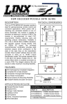
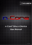
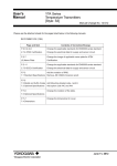
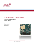
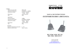
FCTN-DEC1-xxx
OEM DECODER MODULE DATA GUIDE
DESCRIPTION
PHYSICAL DIMENSIONS
The Linx FCTN-DEC1-xxx decoder module is
ideal for general-purpose remote-control and
command applications. When paired with a
matching Linx command module or Linx LC
Series or KH Series transmitter, the module is
capable of operation at distances up to 150ft.
The module is pre-authorized to meet FCC
requirements, thereby reducing costs and
speeding product introduction. Available in
315, 418 or 433.92MHz (418MHz standard),
this decoder module mounts directly onto
an OEM’s PC board. The on-board
receiver/decoder combination provides eight
switched outputs that correspond to the state
of the data lines on the transmitter’s encoder.
Nine tri-state address lines are also provided
to allow up to 19,683 unique identification
codes. The module operates from 5VDC at
8mA typical. Header pins on 0.100" centers
allow direct or socketed connection to a user’s
PCB. The integral antenna tilts and swivels to
allow maximum mounting flexibility.
0.80
0.35"
0.20"
1.58"
1
20
2
19
3
18
4
17
5
16
6
15
7
14
0.145"
13
8
9
12
10
11
.06"
1.15"
0.170"
0.160"
0.060"
0.100"
4.13"
(315-433MHz)
0.300"
0.44"
0.26"
FEATURES
■
■
■
■
■
■
Pre-Authorized for Immediate Integration
Complete RF to Data Solution
Convenient Through-hole Package
Low Power Consumption
Swivel Antenna for Mounting Flexibility
8 Data/9 Address Encoder On-board
1.02"
Pin Dia.
.032"
Pin Dia.
.025"
1.04"
0.100" typ
Figure 1: Physical Dimensions
APPLICATIONS INCLUDE
■
■
■
■
■
■
■
General Remote Control
Keyless Entry
Garage / Gate Openers
Lighting Control
Call Systems
Home / Industrial Automation
Wire Elimination
ORDERING INFORMATION
PART #
DESCRIPTION
FCTN-DEC1-315 315MHz Decoder Module
FCTN-DEC1-418 *418MHz Decoder Module
FCTN-DEC1-433 433.92MHz Decoder Module
* = Standard Frequency
Revised 10/07/03
THEORY OF OPERATION
SETTING DECODER MODULE’S ADDRESS
The FCTN-DEC1-xxx decoder module combines the popular Linx LC series
receiver with a decoder IC and RA series antenna in a convenient through-hole
package. When transmitted data is received, the data is presented to the
decoder. The decoder detects the logic states of the address lines. If these match
with the address settings of the transmitter, the decoders output(s) are set to
replicate the state of the transmitter’s data lines.
Parameter
Operating Voltage
Current Continuous
Receive Frequency
Sensitivity@10-5BER
Output Drive Current
VOH=0.9vcc
(sink or source)
Min.
Typ.
Max.
Units
4.0
315
-92
5
9
418
-95
5.2
10
433.92
VDC
mA
MHz*
.6
1.2
Figure 2: Electrical Specifications
mA
Pin# Name
Pin#
Name
1
Address 6
20
Address 5
2
Address 7
19
Address 4
3
Address 8
18
Address 3
4
Data 0
17
Address 2
5
VCC
16
Address 1
6
Data 5
15
Address 0
7
Data 4
14
Data 6
8
Data 3
13
Data 7
9
Data 2
12
Valid TX
10
Data 1
11
GND
* Model Dependent
OUTPUT PIN CONSIDERATIONS
The output pins will normally require buffering
due to their low sink or source current
capability. The external addition of a transistor
or other buffer is recommended to provide the
appropriate sink or source current for devices
such as relays, LED’s or motors.
POWER SUPPLY REQUIREMENTS
The user must provide a clean source of power
to the module to ensure proper operation.
Power-supply noise will manifest itself as AM
and FM noise and can significantly affect
transceiver performance. Providing a clean
power supply for the module should be a high
design priority. The module’s power-supply line
should have bypass capacitors configured as
shown. Actual capacitor values will vary
depending on noise conditions.
CONTENTION CONSIDERATIONS
An unlimited number of decoder modules may be operated in proximity without
interference. It is important, however, to understand that only one transmitter at
a time can be activated within a reception area. While the transmitted signal
consists of encoded digital data, only one carrier of any frequency can occupy
airspace without contention at any given time.
COMPLIANCE REQUIREMENTS (LABELING)
The FCTN-DEC1-xxx has been tested by an FCC-approved facility and found to
comply will all applicable FCC requirements as of the date, of this document. A
declaration of conformity (DOC) is on file. It is the user’s responsibility to consult
the FCC or other testing body to determine what additional testing may be
required on the user’s completed product. In products where no additional testing
is required, the product may be offered for sale when labeled in the following
manner:
• The following label shall be affixed in a conspicuous location to any device selfcertified under the FCC's Declaration of Conformity process, when the product is
authorized based on assembly using separately authorized components and the
resulting product does not require additional testing:
Your Company Name Your Product Name/ID#
Vcc to
module
Assembled From
Tested Components
(Complete System Not Tested)
FOR HOME OR OFFICE USE
Vcc IN
>10µF
.1µF
LAYOUT CONSIDERATIONS
A 1/4 wave antenna such as that employed on the FCTN-DEC1-xxx utilizes the
groundplane as the antenna's counterpoise. In order to achieve the best range
and uniformity, the designer should provide an additional external groundplane.
This can be accomplished in several ways, but a ground fill on the product’s PC
board will generally suffice. The mounting hole beside the antenna must be tied
directly to adequate groundplane no greater than 1/2" away to achieve desired
range.
Page 2
Nine tri-state address lines are provided that allow the selection of up to 19,683
unique identification codes. The address lines are normally attached to a DIP
switch or PCB Jumpers. *Note: Tri-State means the address lines have three
distinct states; high, low, and floating. The data lines will not function unless the
address lines share identical states with the encoder address lines.
• When the device is constructed in two or more sections connected by wires and
marketed together, the label is required to be affixed only to the main control unit.
• When the device is so small or for such use that it is not practical to place the
statement on the unit itself, the information shown on the label shall be placed in
a prominent location in the instruction manual or pamphlet supplied to the user
or, alternatively, shall be placed on the container in which the device is marketed.
However, the unique FCC logo, device trade name, and model number must be
present on the device.
• The label shall not be a stick-on paper label. The label shall be "permanently
affixed" to the device (meaning the label is etched, engraved, stamped, silkscreened, indelibly printed on a permanently attached part of the device or on a
nameplate fastened to the equipment by welding, riveting, or a permanent
adhesive. The label must be designed to last the expected lifetime of the
equipment in the environment in which the equipment may be operated and may
not be readily detachable.
Page 3
COMPLIANCE REQUIREMENTS (INSTRUCTION MANUAL)
For products containing the FCTN-DEC1-xxx, it is necessary to include the
following statement in the end product’s instruction manual or insert card.
This equipment has been tested and found to comply with the
limits for a Class B digital device, pursuant to part I5 of the FCC
Rules. These limits are designed to provide reasonable
protection against harmful interference in a residential
installation. This equipment generates, uses and can radiate
radio frequency energy and, if not installed and used in
accordance with the instructions, may cause harmful
interference to radio communications. However, there is no
guarantee that interference will not occur in a particular
installation. If this equipment does cause harmful interference
to radio or television reception, which can be determined by
turning the equipment off and on, the user is encouraged to try
to correct the interference by one or more of the following
measures:
• Reorient or relocate the receiving antenna.
• Increase the separation between the equipment and
receiver.
• Connect the equipment into an outlet on a circuit different
from that to which the receiver is connected.
• Consult the dealer or an experienced radio/TV technician
for help.
In order to maintain compliance with FCC regulations, shielded
cables must be used with this equipment. Operation with nonapproved equipment or unshielded cables is likely to result in
interference to radio and TV reception. The user is cautioned
that changes and modifications made to the equipment without
the approval of manufacturer could void the user's authority to
operate this equipment.
Place the above statement in the instruction manual or insert card.
Page 4
Typical Application for FCTN-DEC1-xxx
INSTRUCTIONS TO THE USER
Page 5
DECLARATION OF CONFORMITY
REFERENCE SECTION
The following declarations of conformity are on file at Linx Technologies and may
be inspected on request.
Receiver Module 315MHz
TRADE NAME:
MODEL NUMBER:
COMPLIANCE TEST REPORT NUMBER:
COMPLIANCE TEST REPORT DATE:
RESPONSIBLE PARTY (IN USA):
DECLARATION OF CONFORMITY
TRADE NAME:
Receiver Module
MODEL NUMBER:
RT-418-CTL
COMPLIANCE TEST REPORT NUMBER:
B90429D1
COMPLIANCE TEST REPORT DATE:
4/29/99
RESPONSIBLE PARTY (IN USA):
Linx Technologies, Inc.
ADDRESS:
575 SE Ashley Place, Grants Pass, OR 97526
TELEPHONE:
541-471-6256
This equipment has been tested and found to comply with
the limits for a Class B digital device, pursuant to Part 15 of
the FCC rules. These limits are designed to provide
reasonable protection against harmful interference in a
residential installation. This equipment generates, uses, and
can radiate radio frequency energy and, if not installed and
used in accordance with the instructions, may cause harmful
interference to radio communications. However, there is no
guarantee that interference will not occur in a particular
installation.
541-471-6256
TELEPHONE:
This equipment has been tested and found to comply with the limits for a Class B
digital device, pursuant to Part 15 of the FCC rules. These limits are designed to
provide reasonable protection against harmful interference in a residential installation.
This equipment generates, uses, and can radiate radio frequency energy and, if not
installed and used in accordance with the instructions, may cause harmful
interference to radio communications. However, there is no guarantee that
interference will not occur in a particular installation.
If the unit does cause harmful interference to radio or television reception, please
refer to your user's manual for instructions on correcting the problem.
I, the undersigned, hereby declare that the equipment specified above conforms to
the above requirements.
T
E
Y
T
O
N
Place: Grants Pass, OR
Date:
Place: Grants Pass, OR
Name and Signature On File
Date: August 19,1996
Title: Linx FCC Coordinator
Signature:
Full Name:
DECLARATION OF CONFORMITY
MODEL NUMBER:
COMPLIANCE TEST REPORT NUMBER:
COMPLIANCE TEST REPORT DATE:
RESPONSIBLE PARTY (IN USA):
I, the undersigned, hereby declare that the equipment
specified above conforms to the above requirements.
Linx Technologies, Inc.
575 SE Ashley Place, Grants Pass, OR 97526
ADDRESS:
TRADE NAME:
If the unit does cause harmful interference to radio or
television reception, please refer to your user's manual for
instructions on correcting the problem.
D
E
V
I
E
C
E
R
RT-315-CTL
ADDRESS:
TELEPHONE:
Receiver Module 433 MHz
D
E
V
I
E
C
RE
RT-433-CTL
Linx Technologies, Inc.
575 SE Ashley Place, Grants Pass, OR 97526
541-471-6256
This equipment has been tested and found to comply with the limits for a Class B
digital device, pursuant to Part 15 of the FCC rules. These limits are designed to
provide reasonable protection against harmful interference in a residential installation.
This equipment generates, uses, and can radiate radio frequency energy and, if not
installed and used in accordance with the instructions, may cause harmful
interference to radio communications. However, there is no guarantee that
interference will not occur in a particular installation.
If the unit does cause harmful interference to radio or television reception, please
refer to your user's manual for instructions on correcting the problem.
I, the undersigned, hereby declare that the equipment specified above conforms to
the above requirements.
T
E
Y
T
O
N
Place: Grants Pass, OR
Date:
Signature:
Full Name:
Page 6
Page 7
U.S. CORPORATE HEADQUARTERS:
LINX TECHNOLOGIES, INC.
575 S.E. ASHLEY PLACE
GRANTS PASS, OR 97526
Phone: (541) 471-6256
FAX: (541) 471-6251
http://www.linxtechnologies.com
Disclaimer
Linx Technologies is continually striving to improve the quality and function of its products; for
this reason, we reserve the right to make changes without notice. The information contained in
this Data Sheet is believed to be accurate as of the time of publication. Specifications are based
on representative lot samples. Values may vary from lot to lot and are not guaranteed. Linx
Technologies makes no guarantee, warranty, or representation regarding the suitability or
legality of any product for use in a specific application. None of these devices is intended for use
in applications of a critical nature where the safety of life or property is at risk. The user assumes
full liability for the use of product in such applications. Under no conditions will Linx Technologies
be responsible for losses arising from the use or failure of the device in any application, other
than the repair, replacement, or refund limited to the original product purchase price. Some
devices described in this publication are patented. Under no circumstances shall any user be
conveyed any license or right to the use or ownership of these patents.
Page 8
© 2003 by Linx Technologies, Inc. The stylized
Linx logo, Linx, and “Wireless Made Simple”
are the trademarks of Linx Technologies, Inc.
Printed in U.S.A.