1
DT81
Series 2
data†aker
®
Data Logger
Specifications
Intelligent Data Logging Products
• USB memory for easy data & program transfer
• Dual Channel Isolation Technology
• Serial ‘Smart Sensor’ port
• User Definable allocation of memory size & mode
• Web server for improved browser access
• FTP for automatic data transfer
• Modbus for SCADA connection
• SDI-12 (multiple networks)
• Up to 3 Analog (± 30V) sensor inputs
• 8 Flexible Digital channels
Feature Packed Value for Money!
Applications include:
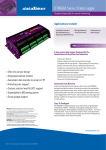
The dataTaker DT81 is the answer to the end user or OEM requiring fewer channels whilst
demanding the powerful features and flexibility of the DT80.
• Research & Development
With support for SDI-12 sensors, Modbus for SCADA systems and Web enabled features, the
DT81 is ready to be rolled out into tomorrow’s environmental or industrial monitoring projects.
• Weather Stations
The DT81 is a robust, stand alone, low power and economical data logger. It’s USB memory stick
support, 18 bit resolution and extensive communications capabilities make it a powerful partner.
• Environmental Monitoring
• Agricultural Research
• Total Energy Monitoring
• Temperature Profiling
Versatile Measurement
• Aquaculture
Analog and digital channels, high-speed counter inputs, phase encoder input and programmable
serial sensor channel allow the DT81 to easily connect to most sensors and data measurement
sources. Temperature, voltage, current, 4-20mA loops, resistance, bridges, strain gauges,
frequency, digital, serial and calculated measurements can all be scaled, logged and returned
in engineering units or within statistical reporting. Group sampling, logging, alarm and control
tasks within schedules to suit your requirements. Smart sensors, GPS, PLCs and other intelligent
devices are supported via a serial sensor port (RS232), with our optional CANgate interface
available for CAN bus applications.
• Structural Monitoring
Superior Data Storage and Communications
• Load Cells
Store up to 10 million data points in user defined memory, log as much or as little as you
need with independent control of schedule size and mode. Overwrite or stop logging once
allocated memory is full. Archive data on alarm event, copy to USB memory or transfer via FTP,
the choice is yours.
• Strain Gauges
• Process Monitoring
• Fault Identification
• Machine Down Time
• Pressure
• Flow
• Vehicle Testing
• GPS
• CANgate (optional)
• CAN bus
Communications features include RS232 with modem support, USB, Ethernet and USB memory
stick ports. Connect to the DT81 locally, remotely or over the Internet. The web server allows
browser access to data and files, FTP provides data to your office over the internet or mobile
phone network, without the need for polling or specific host software.
• J1939
• OBDII
Take the next step and experience the DT81 by contacting your local distributor
or dataTaker office.
FREE
Software &
Technical
Support
Australasia
China
Europe
Americas
Datataker
5 Caribbean Drive
Scoresby, Melbourne
Victoria 3179
Tel: +61 3 9757 4477
Fax: +61 3 9753 3483
Email: [email protected]
Datataker China Limited
Room 1635,
Haidian New Technology Building,
No. 65 West Road North 4th Ring Road,
Haidian District, Beijing P.R.C.:100080
Tel: 86-10-8288 6646
Fax: 86-10-8288 6649
Email: [email protected]
Grant Instruments (Cambridge) Ltd
Shepreth
Cambridgeshire
SG8 6GB
Tel: +44 (0) 1763 264780
Fax: +44 (0) 1763 262410
Email: [email protected]
Computer Aided Solutions
8588 Mayfield Rd, Suite One
Chesterland, OH 44026
Tel: +1 800 9 LOGGER
Tel: +1 440 729 2570
Fax: +1 440 729 2586
Email: [email protected]
www.datataker.com
Analog Channels
Digital Channels
Network (TCP/IP) Services
1 analog input channel
The channel supports: one isolated 3-wire or 4-wire
input, or two isolated 2-wire inputs,
or three common referenced 2-wire inputs.
Digital Input/Outputs
Uses Ethernet and/or Host RS232 (PPP) ports
4 bi-directional channels
Input Type: 4 logic level (max 20/30V)
Output Type: 3 with open drain FET
(max: 30V, 100mA), 1 with logic output.
Command Interface
Relay Output
Access current data and status from any web browser.
Custom pages can be defined. Download data in CSV
format. Command interface window. Define mimic
displays.
Fundamental Input Ranges
The fundamental inputs that the DT80 can measure
are voltage, current, resistance and frequency.
All other measurements are derived from these.
Full Scale
Resolution
Full Scale
Resolution
±30 mVdc
±300 mVdc
±3 Vdc
±30 Vdc
±0.3 mA
±3 mA
±30 mA
0.25 μV
2.5 μV
25 μV
250 μV
2.5 nA
25 nA
250 nA
100 Ω
1000 Ω
10,000 Ω
100 Hz
10 kHz
1.5 mΩ
15 mΩ
150.00 mΩ
0.0002 %
0.0002 %
Auto-ranging is supported over 3 ranges.
Accuracy
Measurement at ...
5°C to 40°C
– 45°C to 70°C
DC Voltage
DC Current
DC Resistance
Frequency
0.1%
0.15%
0.1%
0.1%
0.35%
0.45%
0.35%
0.25%
Access the ASCII command interface of the DT80 via
TCP/IP
Web Server
1 latching relay, contacts (max: 30Vdc, 1A)
Counter Channels
Modbus Server (slave)
Low Speed Counters
4 counters shared with digital inputs.
Low speed counters do not function in sleep mode.
Size: 32 bit
Max Count rate: 10 Hz
Access current data and status from any Modbus client
(e.g. SCADA system)
Dedicated Counter Inputs
FTP Client
4 high speed or 1 phase encoder (quadrature) inputs
Size: 32 bit
Max Count rate: 10 kHz
Input type: 2 logic level inputs (max ±30V), 2 sensitive
inputs (10mV) for magnetic pick-ups (max ±10V)
Automatically upload logged data direct to an FTP server
Serial Channels
Accuracy table above is % of reading ±0.01% of full scale.
SDI-12
Sampling
1 SDI-12 input, shared with digital channel.
The input can support multiple SDI-12 sensors.
Integrates over 50/60Hz line period for accuracy and
noise rejection
Maximum sample speed: 25Hz
Effective resolution: 18 bits
Linearity: 0.01%
Common mode rejection: >90dB
Line series mode rejection: >35dB
Inputs
Inter-Channel Isolation: 100V (relay switching)
Analog Section Isolation: 100V (opto-isolated)
Input impedance: 100KΩ, >100MΩ
Common mode range: ±3.5V or ±35V on 30V range
Sensor Excitation (Supply)
Analog channel: selectable 250μA or 2.5mA precision
current source, 4.5V voltage source, or switched external
supply.
General Purpose: Switchable 12V regulated supply for
powering sensors & accessories. (max 150mA)
Analog Sensors
Calculated Channels
Combine values from analog, digital and serial sensors
using expressions involving variables and functions.
Functions: An extensive range of Arithmetic,
Trigonometric, Relational, Logical and Statistical
functions are available.
Alarms
Condition: high, low, within range and outside range
Delay: optional time period for alarm response
Actions: set digital outputs, transmit message, execute
any dataTaker command.
Data Storage
Internal Store
RTDs
Removable USB store device
(optional accessory)
Types supported: LM34 - 60, AD590, 592, TMPxx
LM135, 235, 335
Number of schedules: 11
Schedule rates: 10ms to days
Capacity: 128MB = approx 10,000,000 data points
Types: compatible with USB 1.1 or USB 2.0 drives, e.g. Flash drive.
Capacity: approx. 90,000 data points per megabyte.
Communication Interfaces
Ethernet Port
Interface: USB 1.1 (virtual COM port)
Protocol: ASCII command
Power Supply
External voltage range: 10 to 30Vdc
Internal battery: 6Vdc 1.2Ahr lead acid
Peak Power: 12W (12Vdc 1A)
Average power Consumption
Using 12Vdc external power source
Sampling Speed
Average Power
1 second
5 second
30 second
5 minutes
1 hour
1350 mW
500 mW
135 mW
70 mW
60 mW
Typical Operating Time
from internal 6Vdc, 1.2Ahr battery
Sampling Speed
Operating Time
1
5
1
1
6.5 hours
1 day
10 days
3.5 months
second
second
minute
hour
Physical and Environment
Construction: Powder coated zinc and
anodized aluminum.
Dimensions: 180 x 137 x 65mm
Weight: 1.5kg (4kg shipping)
Temperature range: –45°C to 70°C *
Humidity: 85% RH, non-condensing
*reduced battery life and LCD operation
outside range –15°C to 50°C
Optional Accessories
Host RS232 Port
Speed: 300 to 115200 baud (57,600 default)
Flow Control: Hardware (RTS/CTS),
Software (XON/XOFF), None
Handshake lines: DCD, DSR, DTR, RTS, CTS
Modem support: auto-answer and dial out
Protocols: ASCII Command, TCP/IP (PPP),
Modbus, Serial Sensor
For full technical specifications download the
user’s manual from our website.
Normal resolution: 200μs
Accuracy: ±1 min/year (0°C to 40°C),
±4 min/year (-40°C to 70°C)
Resource CD: includes software, video training
and user manual.
Comms cable: USB cable
Line adaptor: 110/240Vac to 15Vdc, 800mA
USB Port
Configurations: ¼, ½ & full bridge
Excitation: voltage or current
Internal 100R shunt or external shunt resistor
Firmware Upgrade
Accessories Included
Interface: 10BaseT (10Mbps)
Protocol: TCP/IP
Strain Gauge and Bridge Sensors
4-20mA Current Loop
Type: LCD, 2 line by 16 characters, backlight.
Display Functions: channel data, alarms, system status.
Keypad: 6 keys for scrolling and function execution.
Status LEDs: 4 for sample, disk, attention and power.
Real Time Clock
Types: B, C, D, E, G, J, K, N, R, S, T
Calibration standard: ITS-90
Monolithic Temperature Sensors
Display and Keypad
Flexible options to allow data to be logged from a wide
range of smart sensors and data streams.
Available ports: Host RS232 Port*
Baud rate: 300 to 115200
*If used as a Serial Sensor channel then the Host Port
is not available for other communications.
Thermocouples
Types: YSI 400xx Series, other types*
Resistance range: <10kΩ**
* Other thermistor types are supported by thermistor
scaling and calculated channels.
**Resistance range can be increased with the use of
a parallel resistor.
System
Via: RS232, Ethernet, USB or USB disk.
Scheduling of Data Acquisition
Thermistors
Access logged data from any FTP client or web browser
Generic Serial Sensor
Supports a wide range of sensors including, but not
limited to, those listed below. A wide range of sensor
scaling and linearising facilities including polynomials,
expressions and functions.
Materials supported: Pt, Ni, Cu
Resistance range: 10Ω to 10KΩ
FTP Server
A range of accessories are available. Contact your local
distributor or visit www.datataker.com
data†aker
®
Your local distributor
www.datataker.com
For further information on the dataTaker range, or for useful downloads, visit the Datataker web site
at www.datataker.com or contact your nearest Datataker office or distributor.
Quality Statement: Datataker operates a Quality Management System complying with IS09001:2000.
It is Datataker’s policy to supply customers with products which are fit for their intended purpose, safe in use,
perform reliably to published specification and are backed by a fast and efficient customer support service.
Trademarks: dataTaker is a registered trademark of Biolab (Aust) Pty Ltd trading as Datataker.
Specifications: Biolab (Aust) Pty Ltd trading as Datataker reserves the right to change product specifications
at any time without notice.
Designed and Manufactured in Australia. Biolab (Aust) Pty Ltd trading as Datataker
TS-0061-C1
Warranty: All dataTaker Data Loggers are covered by a 3 year warranty on workmanship and parts.