1
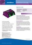
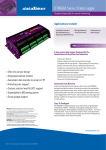
DT82E Series 3 Data Logger
Designed especially for environmental monitoring
Applications include:
Environmental Monitoring Agricultural Research
Research & Development Total Energy Monitoring
Weather Stations
Temperature Profiling
Thermistor Arrays
Aquaculture
Wind Power Generation
*FREE Software & Technical Support
The Smarter Solution
» Low power design for remote applications
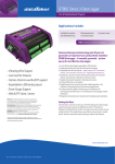
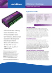
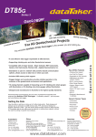
The dataTaker DT82E is a smart data logger designed especially for
environmental monitoring. The DT82E is a robust, low power data
logger featuring USB memory stick support, 18-bit resolution, extensive
communications capabilities and built-in display. The dataTaker DT82E’s
Dual Channel concept allows up to 4 isolated or 6 common referenced analog
inputs to be used simultaneously in various combinations. With advanced
networking capability (FTP and Web interface), one SDI-12 sensor channel
(supporting up to 10 sensors) and switchable 12V regulated output to power
sensors, the DT82E is ready to be deployed.
» Dual Channel Isolation Technology
Versatile Measurement
» 1 SDI-12 input
» Serial ‘Smart Sensor’ port
» FTP for automatic data transfer
» Modbus for SCADA connection
» Up to 6 Analog (± 30V) sensor inputs
»USB memory for easy data and
program transfer
Warranty: All dataTaker Data Loggers are covered by a 3 year warranty
on workmanship and parts. For further information on the dataTaker range,
or for useful downloads, visit the dataTaker web site at www.datataker.
com or contact your nearest dataTaker office or distributor.
Quality Statement: dataTaker operates a Quality Management System complying
with IS09001:2008.It is dataTaker’s policy to supply customers with products
which are fit for their intended purpose, safe in use, perform reliably to published
specification and are backed by a fast and efficient customer support service.
Trademarks: dataTaker is a registered trademark .
Specifications: dataTaker reserves the right to change product specifications
at any time without notice. Designed and Manufactured in Australia.
Inputs include analog and digital channels as well as high-speed counters.
Temperature, voltage, current, 4-20mA loops, resistance, bridges, strain
gauges, frequency, digital, serial and calculated measurements can all
be scaled, logged and returned in engineering units or within statistical
reporting. Set up sampling, logging, alarm and control tasks to suit
your own requirements, or interface with smart sensors, GPS and other
intelligent devices expand the DT82E’s flexibility.
Superior Data Storage & Communications
With the standard unit able to store up to 10 million data points (expandable)
you can log as much or as little as you need. Overwrite or stop logging once
allocated memory is full, archive data on alarm event, copy to USB memory
or transfer via FTP, the choice is yours. Communications features include
RS232, USB and Ethernet, connect to the DT80 locally, remotely through a
modem or over the Internet. The web interface allows users to configure the
DT80, access logged data and see current measurements as mimics or in a
list using a web browser. FTP provides data to your office over the internet or
mobile phone network, without the need for polling or specific host software.
*Our ability to provide free software and support is dependent on applicable export control laws
(including those of the United States) and the export policy from time to time of Thermo Fisher Scientific Inc.
www.datataker.com
©2011 Thermo Fisher Scientific Inc. All rights reserved. A.B.N. 52 058 390 917
dEX Logger Software
Easy configuration
» Built-in software - no application to install
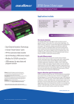
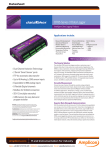
The dEX configuration editor allows you to view, edit and save logger
configurations in an easy-to-use Windows Explorer style user interface.
» Runs directly from your web browser
» Accessible by Ethernet or USB1 connection
» Intuitive graphical interface
» Easy-to-use configuration editor
» Access live and historical data
» View data as charts, mimics and tables
Real-time monitoring
dEX displays real-time sensor measurements, calculations and
diagnostic information using mimics, tables and trend charts.
What is dEX?
dEX is an intuitive graphical interface that allows you
to configure your data logger, view real-time data
in mimics, trend charts or tables and retrieve your
historical data for analysis.
dEX runs directly from your web browser and can be
accessed either locally or remotely, anywhere that a
TCP/IP connection is available including worldwide over
the Internet. You can use any of the logger’s built-in
communications ports to view dEX including Ethernet,
USB1 and RS-232.
Data retrieval
dEX allows you to retrieve your data at the click of a mouse button.
Just select either All, Range or New Data Only.
Browser-based solution
dEX comes pre-installed on every logger in the DT80 range2. The
software loads in your web browser so there is no need to install
cumbersome applications on your computer. Being browser-based,
dEX is cross-platform and will work on all major operating systems
including Windows, Mac and Linux. To simplify it even further, dEX
starts automatically in your default web browser when you connect to
your logger using a USB cable1.
Data that is compatible with your applicatons
Logged data is ready to import into common spreadsheet and data
processing applications such as Excel for further analysis and
reporting. Data can be saved to your computer in comma separated
(.CSV) format or our proprietary binary (.DBD) format.
Command window
The command window provides a terminal interface which allows
the built-in command language of the logger to be used. Macro
buttons allow common commands to be sent on a button press.
Configuration editor
The configuration editor allows you to view, edit and save
logger configurations in an easy-to-use Windows Explorer style
user interface. Tree view of configuration allows definition of
measurement schedules and measurements.
Wiring diagrams show available wiring configurations for each
sensor type. Configuration can be stored and retrieved on either the
logger or a local computer.
R
Platinum RTD (4 wire)
Channel list
Displays name, value, units, alarm state, time stamp and logging
state for each measurement.
Customisation of the application
The menu options, mimics panels and mimics can be added or
removed to suit novice or advanced users. The color and brand
name images within dEX can be customised to match corporate
requirements or for personal preference.
Mimics are organised into panels which can be modified to highlight
custom alarm conditions or data grouping. Mimics include dials, bar
graphs, thermometers etc. Real-time chart recorder mimic allows you
to view trends and historical data over a custom time/date range. Up
to 16 mimics can be displayed on up to 5 mimic pages (default is 1
page of 6 mimics).
Minimum system requirements
- Web Browser (tested with): Internet Explorer V7 and above, Firefox,
Safari & Google Chrome
- TCP/IP connection
- Adobe flash player 10 or higher
- Screen resolution of 1024 x 768
Voltage bridge (+ / #)
Chart recorder mimic
Real-time trending for sensors, calculations or other data. Supports up-to 5 traces per chart and up-to 2 Y-axes. Backfills with historical data stored in logger.
R
1.
2.
USB port equipped models only.
dEX operates on all DT80 range Series 2 & Series 3 models (DT80, DT81, DT82E, DT85, DT80G, DT85G). The latest firmware which
includes dEX is available for download from the dataTaker website. DT80 range Series 1 models do not support dEX.
The difference is dEX!
Technical Specifications
Analog Channels
2 analog input channels
Each channel is independent and supports: one isolated
3-wire or 4-wire input, or two isolated 2-wire inputs, or
three common referenced 2-wire inputs.
The following maximums apply.
Two wire with common reference terminal: 6
Two wire isolated: 4
Three and four wire isolated: 2
Fundamental Input Ranges
The fundamental inputs that the DT80 can measure are
voltage, current, resistance and frequency. All other
measurements are derived from these.
Full Scale
Res olution
Full Scale
±30 mVdc
0.25 μV
100 Ω
±300 mVdc
2.5 μV
1000 Ω
±3 Vdc
25 μV
10,000 Ω
±30 Vdc
250 μV
100 Hz
±0.3 mA
2.5 nA
10 kHz
±3 mA
25 nA
±30 mA
250 nA
Auto-ranging is supported over 3 ranges.
Resolution
1.5 mΩ
15 mΩ
150.00 mΩ
0.0002 %
0.0002 %
Measurement at ...
5°C to 40°C
– 45°C to 70°C
DC Voltage
DC Current
DC Resistance
Frequency
0.1%
0.15%
0.1%
0.1%
0.35%
0.45%
0.35%
0.25%
Accuracy table above is % of reading ±0.01% of full scale.
Sampling
Integrates over 50/60Hz line period for
accuracy and noise rejection
Maximum sample speed: 25Hz
Effective resolution: 18 bits
Linearity: 0.01%
Common mode rejection: >90dB
Line series mode rejection: >35dB
Inputs
Inter-Channel Isolation: 100V (relay switching)
Analog Section Isolation: 100V (opto-isolated)
Input impedance: >100MΩ, 100KΩ (30v range)
Common mode range: ±3.5V or ±35V on 30V range
Sensor Excitation (Supply)
Analog channels: selectable 250μA or 2.5mA precision
current source, 4.5V voltage source, or switched external
supply
General Purpose: Switchable 12V regulated supply for
powering sensors & accessories (max 150mA)
Switchable 5V regulated supply for powering analog
sensors (max 25mA)
Analog Sensors
Supports a wide range of sensors including, but not limited
to, those listed below. A wide range of sensor scaling and
linearising facilities including polynomials, expressions
and functions.
Thermocouples
Types: B, C, D, E, G, J, K, N, R, S, T
Calibration standard: ITS-90
RTDs
Materials supported: Pt, Ni, Cu
Resistance range: 10Ω to 10KΩ
Thermistors
Types: YSI 400xx Series, other types*
Resistance range: <10kΩ**
* Other thermistor types are supported by thermistor scaling and calculated
channels.
**Resistance range can be increased with the use of a parallel resistor.
Low Speed Counters
4 counters shared with digital inputs.
Low speed counters do not function in sleep mode.
Size: 32 bit
Max Count rate: 10 Hz
Dedicated Counter Inputs
4 high speed inputs
Size: 32 bit
Max Count rate: 100 kHz
Input type: 2 logic level inputs (max ±30V), and 2
programmable inputs as either logic level inputs or
sensitive inputs (10mV) for magnetic pick-ups (max ±10V)
SDI-12
1 SDI-12 input, a digital channel. Input
can support up to 10 SDI-12 sensors.
Generic Serial Sensor
Flexible options to allow data to be logged from a wide
range of smart sensors and data streams.
Available ports: Host RS232 Port*
Baud rate: 300 to 115,200
*If used as a Serial Sensor channel then the Host Port is not available for other
communications.
Calculated Channels
Combine values from analog, digital and serial sensors
using expressions involving variables and functions.
Functions: An extensive range of Arithmetic,
Trigonometric, Relational, Logical and Statistical
functions are available.
Alarms
Condition: high, low, within range and outside range
Delay: optional time period for alarm response
Actions: set digital outputs, transmit message, execute
anydataTaker command.
Scheduling of Data Acquisition
Number of schedules: 11
Schedule rates: 10ms to days
Data Storage
Internal Store
Capacity: 128MB = approx 10,000,000 data points
Removable USB store device
(optional accessory)
Types: compatible with USB 1.1 or USB 2.0 drives,
e.g. Flash drive.
Capacity: approx. 90,000 data points per megabyte
Define mimic displays.
FTP Client
Automatically upload logged data direct to an FTP server.
Modbus Server (Slave)
Access current data and status from any Modbus client
(e.g. SCADA system
System
Display and Keypad
Type: LCD, 2 line by 16 characters, backlight.
Display Functions: channel data, alarms, system status.
Keypad: 6 keys for scrolling and function execution.
Status LEDs: 4 for sample, disk, attention and power.
Firmware Upgrade
Via: RS232, Ethernet, USB disk.
Real Time Clock
Normal resolution: 200μs
Accuracy: ±1 min/year (0°C to 40°C),
±4 min/year (-40°C to 70°C)
Power Supply
External voltage range: 10 to 30Vdc
Peak Power: 6W (typical) (12Vdc 500mA)
Average power Consumption (typical)
Using 12Vdc external power source
Schedule Rate
1 sec
5 sec
30 sec
1 min
5 min
30 min
1 hrs
1 analog sample
Average Power (mW)
560
250
50
30
14
11
11
6 analog samples
Average Power (mW)
926
337
65
38
16
11
11
Physical and Environment
Construction: Powder coated steel and
anodized aluminum.
Dimensions: 180 x 137 x 65mm
Weight: 900 gram (3kg shipping)
Temperature range: –45°C to 70°C *
Humidity: 85% RH, non-condensing
*reduced LCD operation
outside range –15°C to 50°C
Accessories Included
Resource CD: includes software, video training
and user manual.
Comms cable: Ethernet crossover cable
Line adaptor: 110/240Vac to 15Vdc, 800mA
For full technical specifications download the
user’s manual from our website.
Communication Interfaces
Ethernet Port
Interface: 10BaseT (10Mbps)
Protocol: TCP/IP, Modbus Slave
Host RS232 Port
Speed: 300 to 115,200 baud (57,600 default)
Flow Control: Hardware (RTS/CTS),
Software (XON/XOFF), None
Handshake lines: DCD, DSR, DTR, RTS, CTS
Modem support: auto-answer and dial out
Protocols: ASCII Command, TCP/IP (PPP), Serial Sensor,
Modbus Slave
Network (TCP/IP) Services
Uses Ethernet and/or Host RS232 (PPP) ports
Command Interface
Access the ASCII command interface
of the DT82E via TCP/IP
Web Server
Access current data and status from any web browser.
Custom HTML pages can be defined.
Download data in CSV format.
Command interface window.
Your local distributor
CAS Dataloggers
8437 Mayfield Rd.
Chesterland, OH 44026
(800) 956-4437
www.dataloggerinc.com
TS-0076-F1
Monolithic Temperature Sensors
Types supported: LM34 - 60, AD590, 592, TMPxx,
LM135, 235, 335
Strain Gauge and Bridge Sensors
Configurations: ¼ , ½ & full bridge
Excitation: voltage or current
4-20mA Current Loop
Internal 100Ω shunt or external shunt resistor
Digital Input/Outputs
4 bi-directional channels
Input Type: 4 logic level (max 20/30V)
Counter Channels
Serial Channels
Accuracy
Digital Channels
Output Type: 3 with open drain FET(max: 30V, 100mA),
1 with logic output.
Relay Output
1 latching relay, contacts (max: 30Vdc, 1A)